EVGA Classified SR-2 User Manual
Evga dual xeon motherboard user guide
Hide thumbs
Also See for Classified SR-2:
- Key specs (2 pages) ,
- Specifications (2 pages) ,
- Product overview (1 page)
Table of Contents
Advertisement
Advertisement
Table of Contents

Related Manuals for EVGA Classified SR-2


Summary of Contents for EVGA Classified SR-2
- Page 1 User Guide EVGA Classified Super Record 2 (SR-2) Dual Xeon Motherboard...
-
Page 3: Table Of Contents
Before You Begin… ... 8 Parts NOT in the Kit ... 9 Intentions of the Kit ... 9 EVGA Classified Super Record 2 (SR-2) Motherboard ... 10 Motherboard Specifications ... 10 Unpacking and Parts Descriptions ... 12 Unpacking ... 12 Equipment ... - Page 4 LED Status Indicators ... 36 Jumper Settings ... 37 PCI-E Disable Jumper ... 37 Voltage Measure Point ... 38 EVGA Control Panel (ECP) ... 39 Configuring the BIOS ... 47 Enter BIOS Setup ... 48 Main Menu ... 49 Standard BIOS FeaturesMenu……………………………………………………………………….51 System Time/SystemDate…………………………………………………………………………52...
- Page 5 Boot Configuration Features…………………………………………………………………………60 Boot Settings Configuration………………………………………………………………………60 Boot Device Priority………………………………………………………………………………….60 Hard Disk Drives………………………………………………………………………………………60 Power Management Features……………………………………………………………………….61 ACPI Configuration…………………………………………………………………………………..61 Hardware Health Configuration…………………………………………………………………….62 H/W HealthFunction…………………………………………………………………………………62 CPU Fan Mode Setting………………………………………………………………………………62 Frequency/Voltage Control…………………………………………………………………………..62 CPU Configuration……………………………………………………………………………………63 Memory Configuration………………………………………………………………………………63 Voltage Configuration……………………………………………………………………………….64 Signal Tweaks………………………………………………………………………………………….64 EVGA Classified SR-2 Motherboard...
- Page 6 CPU Frequency Setting……………………………………………………………………………..64 CPU Multiplier Setting……………………………………………………………………………….64 QPI Frequency…………………………………………………………………………………………64 Memory Frequency…………………………………………………………………………………..65 Installing Drivers and Software ... 66 Windows XP/Vista/Win7 Drivers Install ... 66 Appendix A. POST Codes ... 67 EVGA Glossary of Terms ... 69...
-
Page 7: List Of Figures
Figure 1. EVGA Classified SR-2 Motherboard Layout ... 15 Figure 2. Chassis Back panel Connectors ... 16 Figure 3. Power Supply Connectors ... 24 Figure 4. Standard BIOS Features Menu………………………………………………………..51 Figure 5. Advanced BIOS Features Menu ... 53 Figure 6. -
Page 8: Before You Begin
Before You Begin… Thank you for purchasing the EVGA Super Record 2 (SR-2) Motherboard. This is the premier dual socket enthusiast class motherboard. With this purchase you not only receive the best dual Xeon motherboard built for the enthusiast, by the enthusiast, you also receive industry leading 24/7 technical support. -
Page 9: Parts Not In The Kit
Graphics Card Power Supply EVGA assumes you have purchased all the necessary parts needed to allow for proper system functionality. Intentions of the Kit This kit provides you with the motherboard and all connecting cables necessary to install the motherboard into a PC case. If you are building a PC, you will use most of the cables provided in the kit. -
Page 10: Evga Classified Super Record 2 (Sr-2) Motherboard
EVGA Classified Super Record (SR-2) Dual Xeon Motherboard Motherboard Specifications Size HPTX (High Performance Technology Extended) form factor of 15 inches x 13.6 inches Microprocessor support Intel 1366 Xeon Dual QPI Microprocessor Operating systems: Supports Windows XP 32bit/64bit , Windows Vista 32bit/64bit or... - Page 11 Low power consumption and power management features Green Function Supports ACPI (Advanced Configuration and Power Interface) Supports S0 (normal), S1 (power on suspend), S3 (suspend to RAM), S4 (Suspend to disk - depends on OS), and S5 (soft - off) EVGA Classified SR-2 Motherboard...
-
Page 12: Unpacking And Parts Descriptions
Unpacking The EVGA Classified SR-2 motherboard comes with all the necessary cables for adding a motherboard to a new chassis. If you are replacing a motherboard, you may not need many of these cables. Be sure to inspect each piece of equipment shipped in the packing box. If anything is missing or damaged, contact your reseller. - Page 13 EVGA Classified SR-2 Motherboard 3 - 2-Port SATA Power Cables Allows a Molex power connector to adapt to a SATA power connector. 1 - 4-Port USB Bracket Provides one (4) additional USB ports on the rear of the case. 6 - SATA Data Cables Used to support the Serial ATA protocol and each one connects to a single drive to the motherboard.
-
Page 14: Evga Classified Sr-2 Motherboard
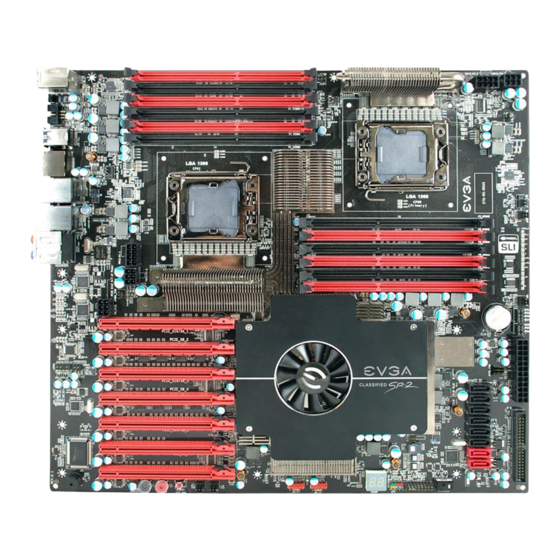
EVGA Classified SR-2 Motherboard The EVGA Classified SR-2 Motherboard with the Intel 5520 and ICH10R chipset is a SLI-ready motherboard. Figure 1 shows the motherboard and Figure 2 shows the back panel connectors. - Page 15 Figure 1. EVGA Classified SR-2 Motherboard Layout 19 18 17 1. Primary CPU socket 2. Secondary CPU socket 3. NVIDIA NF200 Chipsets 4. CPU Fan headers 5. Intel 5520 + ICH10R Chipsets 6. 24-pin ATX power connector 7. Fan connectors 8.
- Page 16 Figure 2. Motherboard I/O Panel Connectors 1. PS/2 Keyboard Port 2. USB 2.0 ports 3. CMOS Clear Button 4. EVBot Connector 5. USB 3.0/2.0 ports (Two) 6. E-SATA ports (Two) 7. Dual Lan Ports with LEDs to indicate status Activity LED Status Blinking (Green) 8.
-
Page 18: Hardware Installation
This section will guide you through the installation of the motherboard. The topics covered in this section are: Preparing the motherboard Installing the CPU’s Installing the CPU fans Installing the memory Installing the motherboard Connecting cables ... -
Page 19: Preparing The Motherboard
It is a good idea to save the cover so that whenever you remove the CPU, you have a safe place to store it. EVGA Classified SR-2 Motherboard contain a CPU or memory. You... -
Page 20: Installing The Cpu Fan
Align the notches of the socket with the notches on the cpu. Lower the processor straight down into the socket without tilting or sliding it into the socket Make sure the CPU is fully seated and level in the socket. Close the load plate over the CPU and press down while you close and engage the socket lever. -
Page 21: Installing Dimms
Align the memory module to the DIMM slot, and insert the module vertically into the DIMM slot. The plastic clips at both sides of the DIMM slot automatically lock the DIMM into the connector. EVGA Classified SR-2 Motherboard DIMM Slot 2 DIMM Slot 1... -
Page 22: Installing The Motherboard
Installing the Motherboard The sequence of installing the motherboard into the chassis depends on the chassis you are using and if you are replacing an existing motherboard or working with an empty chassis. Determine if it would be easier to make all the connections prior to this step or to secure the motherboard and then make all the connections. -
Page 23: Securing The Motherboard Into The Chassis
Align the mounting holes with the studs/spacers. Align the connectors to the I/O shield. Ensure that the fan assembly is aligned with the chassis vents according to the fan assembly instruction. Secure the motherboard with a minimum of nine screws. EVGA Classified SR-2 Motherboard... -
Page 24: Connecting Cables And Setting Switches
Connecting Cables and Setting Switches This section takes you through all the connections and switch settings on the motherboard. This will include: Power Connections 24-pin ATX power ( 8-pin ATX 12V power ( Internal Headers Front Panel Header USB Headers Audio Header ... - Page 25 You can plug in the extra 6 pin PCI-E power connectors (optional) if you need them for extreme overclocking. It is not necessary/required as the motherboard will function perfectly with just one connector in each 8 pin socket. Back panel connector edge EVGA Classified SR-2 Motherboard Signal +3.3V +3.3V PWROK...
-
Page 26: Connecting Ide Hard Disk Drives
Before installing these plugs be ensure that the 8-pin connector is an ATX 12V differential output, and not a PCI-E power connector. Connecting IDE Hard Disk Drives The IDE connector supports Ultra ATA 133/100 IDE hard disk drives. Connect the blue connector (the cable end with a single connector) to the motherboard. -
Page 27: Connecting Serial Ata Cables
EVGA Classified SR-2 Motherboard Connecting Serial ATA Cables The Serial ATA II connector is used to connect a Serial ATA II device to the motherboard. These connectors support the thin Serial ATA II cables for primary storage devices. The current Serial ATA II interface allows up to 300MB/s data transfer rate. -
Page 28: Connecting Internal Headers
Connecting Internal Headers Front Panel Header The front panel header on this motherboard is used to connect the following four cables. (see Table 2 for pin definitions): PWRLED Attach the front panel power LED cable to these two pins of the connector. The Power LED indicates the system’s status. -
Page 29: Usb Headers
Connect the end of the USB cable to the USB 2.0 headers on the motherboard. Table 3. USB 2.0 Header Pins Connector USB 2.0 Header Connector EVGA Classified SR-2 Motherboard Signal 5V_DUAL Empty Signal 5V_DUAL No Connect... -
Page 30: Audio Header
Audio Header The audio connector supports HD audio standard and provides two kinds of audio output choices: the Front Audio, the Rear Audio. The front Audio supports re-tasking function. Table 4. Front Audio Header Connector Front Audio Connector Signal PORT1_L AUD_GND PORT1_R PRECENCE_J... -
Page 31: Fan Connections
CMOS Setup. The fans are automatically turned off after the system enters S3, S4 or S5 mode. EVGA Classified SR-2 Motherboard section of the PC Health Status Note: the CPU fan cable can be either a 3-pin or a 4-pin connector. -
Page 32: Expansion Slots
Expansion Slots The EVGA Classified SR-2 motherboard contains seven (7) PCI-E expansion slots. PCI-E Slot Listing 1 – PCI-E x16/8 slot 2 – PCI-E x8 slot 3 – PCI-E x16/8 slot 4 – PCI-E x8 slot 5 – PCI-E x16/8 slot 6 –... -
Page 33: Pci-E X16 Slots
EVGA Classified SR-2 Motherboard PCI-E x16 Slots These seven PCI-E x16/x8 slots are reserved for graphics cards, and x1/x4 devices. The bandwidth of the x16 slot is up to 4GB/sec (8GB/sec concurrent). The design of this motherboard supports up to Four PCI-E graphics cards using NVIDIA’s SLI technology with multiple displays. -
Page 35: Onboard Buttons
LED remains a solid red The RESET button contains a LED that indicates the activity status of the hard disk drives and will blink accordingly. RESET Button EVGA Classified SR-2 Motherboard External Clear CMOS Button POWER Clear CMOS Button... -
Page 36: Post Port Debug Led And Led Status Indicators
Post Port Debug LED and LED Status Indicators Post Port Debug LED The Debug LED provides two-digit POST codes to show why the system may be failing to boot. It is useful during troubleshooting situations. This Debug LED will also display current CPU temperatures after the system has fully booted into the Operating System. -
Page 37: Jumper Settings
PCI-E Disable Jumper For the ease of troubleshooting multiple graphics cards or testing an individual graphics card’s overclocking, EVGA has implemented seven jumpers you can use to disable individual PCI-E slots. You don’t need to remove any of your graphics cards but simply disable the slot the particular card is in. - Page 38 CPU Disable Jumper For the ease of troubleshooting Dual CPUs or testing an individual CPU’s overclocking, EVGA has implemented two jumpers you can use to disable individual CPUs. You don’t need to remove any of your CPUs but simply disable the particular CPU.
-
Page 39: Voltage Measure Point
Voltage Measure Point The motherboard is equipped with thirteen voltage measure point pads. You can use a meter to measure the voltage at each pad. EVGA Classified SR-2 Motherboard CPU 0 Vcore voltage CPU 1 Vcore voltage Memory Bank 0 voltage... -
Page 40: Evga Control Panel (Ecp)
EVGA Control Panel (On select models) For the convenience of users, EVGA has designed an easy to access control panel: To use the ECP, simply hook up the black ECP cable to the motherboard’s P80P connector at this location, the bottom right corner: The cable should fit into the area high-lighted in green. - Page 41 EVGA Classified SR-2 Motherboard The other end of the cable should be connected to the ECP as shown: **Before turning on the PC, please check to see that the CPU VCore Booster is in the Off position (clicked up).** If you wish to access the PCI-E Disable Function via the ECP, please follow these instructions.
- Page 42 Remove the top 4 jumpers. Connect the PCI-E cable with the red wires occupying the left most pins: Please remember to do this when the PC is not running. Next, connect the other end of PCI-E enable/disable cable onto the ECP as shown:...
- Page 43 EVGA Classified SR-2 Motherboard The red wires should be occupying the pins on the top row. Now, access the Disable/Enable Function at the front of the Control Panel: From right to left, the PCI-E Disable will disable slots 1, 3, 5, 7. When jumper is in top position, PCI-E slot is enabled.
- Page 44 Remove the 2 jumpers. Connect the remaining 3x2 cable connector here, with the red wires on the top row:...
- Page 45 EVGA Classified SR-2 Motherboard Now, access the Disable/Enable Function at the front of the Control Panel:...
- Page 46 From right to left, the CPU Disable jumpers will disable CPU0, CPU1. When jumper is in top position, CPU is enabled. When in bottom position CPU is disabled. CPU VCore Booster For convenience of users when overclocking, the ECP houses 2 CPU VCore Boosters for real-time boost of CPU VCore.
- Page 47 EVGA Classified SR-2 Motherboard...
-
Page 49: Enter Bios Setup
Enter BIOS Setup Main Menu Standard BIOS Features Advanced Chipset Features PCI/PNP Resource Management Boot Configuration Features Power Management Features Hardware Health Configuration Frequency/Voltage Control EVGA Classified SR-2 Motherboard Configuring the BIOS... -
Page 50: Enter Bios Setup
Enter BIOS Setup The BIOS is the communication bridge between hardware and software. Correctly setting the BIOS parameters is critical to maintain optimal system performance. Use the following procedure to verify/change BIOS settings. Power on the computer. Press the of the screen during the Power On Self Test (POST). Press F1 to continue, DEL to enter Setup. -
Page 51: Main Menu
BIOS CMOS Setup Utility Main Menu Standard BIOS Features Use this menu to set up the basic system configuration. EVGA Classified SR-2 Motherboard keys to scroll through the Page Up Page Down to display the associated submenu. Use the arrow... - Page 52 Advanced BIOS Features Use this menu to set up the advanced onboard features such as SATA and USB 3.0 configuration.. Advanced Chipset Features Use this menu to set up onboard peripherals such as USB, LAN, and MAC control. PCI/PNP Resource Management ...
-
Page 53: Standard Bios Featuresmenu
System Memory Size :4088MB System Time System Date :Move Enter:Select F5:Previous Values Figure 4. Standard BIOS Features Menu EVGA Classified SR-2 Motherboard Standard BIOS Features @ 2.67GHz [11:11:00] [Fri 12/21/2012] +/-/:Value F10:Save ESC:Exit F7:Optimized Defaults keys to scroll Help Item... -
Page 54: System Time/Systemdate
System Time / System Date Using the arrow keys, position the cursor over the month, day, and year. Use keys to scroll through dates and times. Note that the weekday (Sun through Sat) cannot be changed. This field changes to correspond to the date you enter. -
Page 55: Ahci Configuration
SATA Master Break Event E-SATA Controller (BackPanel) Configure E-SATA as E-SATA Boot SATA 3.0 Storage Controller :Move Enter:Select F5:Previous Values EVGA Classified SR-2 Motherboard keys to scroll through the options or press to display the sub-menus. Enter [Press Enter] [Press Enter] [Disabled] [Auto]... -
Page 56: Sata Configuration
SATA Configuration Use this to configure your storage drivers and to enable RAID or switch between IDE and AHCI mode. Please note for Windows Vista / Windows 7, it is recommended to use AHCI mode for new system installations. AHCI Configuration This menu will allow you to change advanced AHCI settings, such as S.M.A.R.T. -
Page 57: Sata Configuration
Configure SATA#1 as This option allows Setting of SATA mode. Your options are: IDE, RAID and AHCI. SATA#2 Configuration This option allows setup of SATA #1, your options are: Disable and Enhanced EVGA Classified SR-2 Motherboard [Compatible] Main Level [IDE] [Enhanced]... -
Page 58: Advanced Chipset Features
Advanced Chipset Features Advanced Chipset Settings ______________________________________________ USB Configuration PCI Express Configuration HD Audio USB 3.0 Controller Marvell LAN 1 Marvell LAN 2 LAN Boot P80 Show CPU0 Temperature :Move Enter:Select F7:Previous Values USB Configuration This option menu allows you to enable Legacy USB support, force USB 1.1 mode and more. - Page 59 This function allows you to enable or disable the onboard primary network controller. It is recommended to leave this enabled, unless you are using an external Network Controller, such as an EVGA Killer Xeno card. Marvell LAN 2 ...
-
Page 60: Pci/Pnp Resource Management
PCI/PNP Resource Management Advanced PCI/PnP Settings ______________________________________________ WARNING: Setting wrong values in below sections may cause system to malfunction. Clear NVRAM Plug & Play O/S PCI Latency Timer Allocate IRQ to PCI VGA Palette Snooping PCI IDE BusMaster OffBoard PCI/ISA IDE Card IRQ3 IRQ4 IRQ5... -
Page 61: Allocate Irq To Pci Vga
This function allows the BIOS to use PCI BusMastering for reading or writing to IDE drives. OffBoard PCI/ISA IDE Card This function allows manual override of PCI/ISA external cards. A setting of [Auto] works for most devices. EVGA Classified SR-2 Motherboard... -
Page 62: Boot Configuration Features
Boot Configuration Features Boot Settings ______________________________________________ Boot Settings Configuration[Press Enter] Boot Device Priority Hard Disk Drives :Move Enter:Select F5:Previous Values Boot Settings Configuration This option menu will allow specification of the boot settings such as: Boot screen Logo, Quick boot and Boot up Num-Lock. Boot Device Priority This option menu will allow specification of the boot device priority sequence. -
Page 63: Power Management Features
Enter:Select F5:Previous Values ACPI Configuration This menu will allow adjustment of ACPI configurations. Restore on AC Power Loss This menu allows adjustment of the AC Power Loss parameters. EVGA Classified SR-2 Motherboard [Press Enter] [Power Off] +/-/:Value F10:Save ESC:Exit +/-/PU/PD:Value... -
Page 64: Hardware Health Configuration
Hardware Health Configuration Hardware Health Configure H/W Health Function ______________________________________________ CPU0 Temperature CPU0 PWM Temperature System0 Temperature CPU1 Temperature CPU1 PWM Temperature System1 Temperature JCPU0 Fan Speed JPWR0 Fan Speed JSYS0 Fan Speed JCPU1 Fan Speed JPWR1 Fan Speed JSYS1 Fan Speed :Move Enter:Select F5:Previous Values... -
Page 65: Frequency/Voltage Control
Virtualization Technology, CPU SpeedStep, or CPU power saving options. Memory Configuration This menu will allow the configuration of advanced memory settings, including memory frequency and memory timings. EVGA Classified SR-2 Motherboard AMIBIOS CMOS Setup Utility Frequency/Voltage Control [Press Enter] [Press Enter]... -
Page 66: Voltage Configuration
Voltage Configuration This menu will allow the configuration of all modifiable voltage settings for the system. Signal Tweaks** This menu will allow the fine tuning of specific settings and voltage references and signals. ** Intended for Advanced Users ** CPU Frequency Setting This option allows direct adjustment to the base frequency or Bclk at which the processor will operate at. -
Page 67: Memory Frequency
Memory Frequency This setting allows adjustment to the memory or ram operating frequency. Extreme Cooling This setting adjusts the systems ability to operate at lower temperatures during extreme overclocking. EVGA Classified SR-2 Motherboard... -
Page 68: Installing Drivers And Software
The motherboard supports Windows XP/Vista and Win7 32 & 64 Bit The kit comes with a CD that contains utilities, drivers. The CD that has been shipped with your EVGA Classified SR-2 motherboard contains the following software and drivers: Chipset Drivers ... - Page 69 Uncompress and initialize BIOS module Initialize devices primary Initialize devices secondary Initialize output devices Allocate memory for ADM module Initialize silent boot module Display sign-on message Initialize USB controller Initialize DMAC-1 & DMAC-2 Initialize real time clock Test system memory EVGA Classified SR-2 Motherboard...
- Page 70 Code Description Initialization of chipset registers Detect coprocessor Update CMOS memory size Initialize NUM-LOCK Initialize Int-13 Initialize IPL devices Generate and write contents of ESCD Log errors encountered Display errors, if no display check monitor/graphics card Execute BIOS setup if needed or requested Late POST initialization of chipset registers Build ACPI tables Program peripheral parameters...
-
Page 71: Evga Glossary Of Terms
EVGA Classified SR-2 Motherboard EVGA Glossary of Terms ACPI - Advanced Configuration and Power Interface AFR – Alternate Frame Rendering APIC - Advanced Programmable Interrupt Controller BIOS - Basic Input Output System CD-ROM - Compact Disc Read-Only Memory CMOS - Complementary Metal-Oxide Semiconductor CPU –... - Page 72 HDMI - High-Definition Multimedia Interface HDR – High Dynamic Range Lighting HPET - High Precision Event Timer HT – Hyper-Threading HSF - Heat Sink Fan I/O - Input/Output IDE - Integrated Drive Electronics IEEE - Institute of Electrical and Electronics Engineers IGP - Integrated Graphics Processors IRQ - Interrupt Request JBOD - Just a Bunch of Disks...
- Page 73 EVGA Classified SR-2 Motherboard PCI-E - Peripheral Component Interconnect Express PCI-x - Peripheral Component Interconnect Extended POST – Power on Self Test PWM – Pulse Width Modulation QDR - Quad Data Rate QPI – Quick Path Interconnect RAID - Redundant Array of Inexpensive Disks...
Need help?
Do you have a question about the Classified SR-2 and is the answer not in the manual?
Questions and answers