Table of Contents
Advertisement
Quick Links
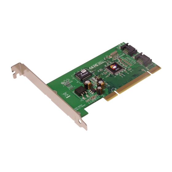
Introducing the Serial ATA PCI RAID
The Serial ATA PCI RAID is an ultra high-speed two
channel Serial ATA controller board for use in
Pentium-class computers. It achieves burst data transfer
rates up to 150MB/s (1.5Gb/s) and supports various
brands of hard disk drives with capacities greater that
137GB.
Features and Benefits
•
Increased performance and security with
Serial ATA RAID
•
Supports 32-bit wide PCI bus at 66MHz and data
transfer rates up to 1.5Gb/s (150MB/s)
•
Supports RAID 0 (stripe) for performance and
RAID 1 (mirror) for data reliability
•
Compliant with Serial ATA 1.0 and PCI 2.2
specifications
•
Coexists with on-board controller
•
Features independent 256-byte FIFOs per channel
for host reads and writes
•
Feature Watch Dog timer for fault resiliency and
flash memory for future BIOS updates
•
Breaks the 137GB barrier! Works with various
brands of large capacity Serial ATA hard disks
04-0373C
Serial ATA PCI RAID
Quick Installation Guide
1
Advertisement
Table of Contents

Related Manuals for SIIG Serial ATA PCI RAID


Summary of Contents for SIIG Serial ATA PCI RAID
-
Page 1: Quick Installation Guide
Serial ATA PCI RAID Quick Installation Guide Introducing the Serial ATA PCI RAID The Serial ATA PCI RAID is an ultra high-speed two channel Serial ATA controller board for use in Pentium-class computers. It achieves burst data transfer rates up to 150MB/s (1.5Gb/s) and supports various brands of hard disk drives with capacities greater that 137GB. - Page 2 System Requirements • Pentium or equivalent PC with an available PCI ® slot • Windows 98SE/ME/2000/XP (32-/64-bit)/Server ® 2003 (32-/64-bit)/Vista (32-/64-bit) Package Contents • Serial ATA PCI RAID board • 2 Serial ATA data cables • Dual Connector Serial ATA power cable •...
-
Page 3: Hardware Installation
Hardware Installation General instructions for installing the card are provided below. Since the design of computer cases and motherboards vary, refer to your computer’s reference manual for further information, if needed. Static Electricity Discharge may permanently damage your system. Discharge any static electricity build up in your body by touching your computer’s case for a few seconds. -
Page 4: Hard Disk Drive
Connect the Serial ATA hard disk drive to the system power supply using the included Serial ATA power cable. Connect one end of the Serial ATA data cable to the hard disk drive. Serial ATA cable Serial ATA power cable Figure 2. -
Page 5: Table Of Contents
RAID Arrays RAID arrays are setup in the Serial ATA PCI RAID BIOS. Find your RAID set from the table of contents. Follow the steps in the order in which they appear. Table of Contents RAID 0 (Striping) ........... page 5-6 RAID 1 (Mirror) .......... -
Page 6: Raid 1 (Mirror)
Press Ctrl+E to exit the BIOS. When asked Are you sure to exit (Y/N)?, press Y to exit and reboot. For Manual Configuration As the BIOS boots press either Ctrl+S or F4 when prompted to enter the RAID BIOS. At the next screen select Create RAID Set, then press Enter. -
Page 7: Rebuilding A Failed Mirror Set
For Existing Hard Drives with Data As the BIOS boots press either Ctrl+S or F4 when prompted to enter the RAID BIOS. At the next screen select Create RAID Set, then press Enter. At the next screen select Mirrored then press Enter. Select Manual configuration, then press Enter. -
Page 8: Deleting Raid Arrays
Select Rebuild Mirror set then press Enter. Select Offline rebuild then press Enter. When asked Are You Sure (Y/N)?, press Y to confirm. The mirror will start to rebuild. When rebuilding finishes, press Ctrl+E to exit. (Rebuilding can take 30-120 minutes depending on the size of the mirror). When asked Are you sure to exit (Y/N)?, press Y to exit and reboot. -
Page 9: Low Level Format
Low Level Format Low Level Format is built into the RAID BIOS to make it more convenient to erase the entire contents of a hard disk drive, including data, drive and partition information. The Low Level Format utility works on single hard drives only, before the RAID set is configured. - Page 10 For An Existing Installation Install the board and boot up to Windows. At the Add New Hardware Wizard, click Next to continue. Select Search for the best driver for your device option then click Next. Insert the driver CD, check CD-ROM drive, uncheck the other check boxes, then click Next.
- Page 11 For An Existing Installation Install the board and boot up to Windows. At the Add New Hardware Wizard, insert the driver Select Automatic search for a better driver (Recommended), then click Next. Accept the default entry then click OK. Click Finish. Remove the driver CD, shutdown Windows, and setup your RAID array.
- Page 12 At the Windows 2000 Setup screen, press F6. When prompted press S to specify the location of the driver. Insert the driver diskette, then press Enter. Select Silicon Image SiI 3x12 SATARaid Controller for Windows NT 4.0 and 2000, then press Enter. Press Enter to finish driver installation, then follow the on-screen instructions to complete Windows 2000 installation.
- Page 13 Follow Microsoft installation procedure to install Windows accordingly. Restart your system when prompted by Windows installation. At the Windows Setup screen, press F6 to install the driver. Insert the driver diskette. Press S then press Enter. Select Silicon Image SiI 3x12 SATARaid Controller for Windows XP/Server 2003/Vista and press Enter.
- Page 14 64-bit Windows XP/Server 2003 For A New Installation A new installation of Windows XP/Server 2003 requires a floppy disk for the driver installation. To make this floppy disk, copy the contents of the 64bit folder, found on the driver CD, onto a blank floppy disk then follow the directions below.
- Page 15 Click Finish, remove the driver CD, shutdown Windows, and setup your RAID array. When Windows resumes, go to SATARaid GUI on page 17 and install the RAID monitoring utility. To Verify 2000/XP/Server 2003 Installation Right click My Computer, click Manage, click Device Manager.
- Page 16 For An Existing Installation Install the board and boot up Windows. At the Found New Hardware window, click Locate and install the driver automatically (recommended). Insert the driver CD, click Continue. Click Next, then click Close. Remove the driver CD, shutdown Windows, and setup your RAID array.
- Page 17 SATARaid GUI The SATARaid GUI provides the user an easy way to monitor and configure your RAID array. It also offers administrative tools to save, copy, or send via E-mail the current configuration. Installing SATARaid GUI For Windows Vista Place the driver CD into the CD-ROM drive. At the AutoPlay window: click Open folder to view files.
- Page 18 For 98SE/ME/2000/XP(32-/64-bit)/Server 2003(32-/64-bit) Place the driver CD into the CD-ROM drive. At the Windows desktop click Start, then Run. Type D:\GUI\Java SATARaid.exe, then click OK. Follow the on-screen instructions to complete the installation (Change D: to match your CD-ROM drive letter) At the Windows desktop click Start, then Run.
- Page 19 Using SATARaid GUI During the installation process, the SATARaid GUI was saved in the Windows Startup folder, a small blue SATARaid logo will appear in the right-hand corner of taskbar. To launch the GUI, simply click on the icon or right click icon and choose Open.
- Page 20 Selecting each different component in the configuration tree provides specific information for that component, such as the chip. By selecting a specific channel the following information is reported.
- Page 21 Selecting a specific drive reports all pertinent information to that drive, including Configuration and Disk Identification information.
- Page 22 Selecting Sets reports on active RAID sets. By selecting the specific RAID set, such as Set 1 which is a Mirrored Set, the type of RAID set, the number of members and capacity is reported.
- Page 23 The Members tab reports the device identification (corresponding with the information in the BIOS) and the state of each device. Besides reporting information, the Members tab of a Mirrored Set allows the user to remove a specific drive from that set. However, a drive cannot be removed from a stripe set as this would destroy all the data.
- Page 24 The device identification, along with the state of each device is also reported in the Members tab window. Note that when a Mirror set is first created, the state of the “destination” drive may report as Rebuild for as much as 30-90 minutes depending on the size of the disk.
- Page 25 Configuration Menu With the SATARaid GUI running, the small SATARaid icon should appear in the bottom right of the computer screen, next to the clock. By right-clicking on the icon and clicking Configure the user may configure SATARaid including customizing the settings for SMTP, E-mail, Notification, Event Level, Log File, Audio, Popup, TrayIcon, Event Table and Event Time.
- Page 26 E-Mail Using the E-mail tab in the Configuration Menu, the user may set the default E-mail address and subject line to where the configuration should be sent. This, however, can be overridden at the time of sending the E-mail. Notification When different types of events occur, SATARaid may be configured to send notices to assigned individual E-mail addresses.
- Page 27 Event Level There are different types of E-mail notifications that may be sent which are set with the Event Level tab. The different levels are: Disabled - No event logs will be sent Informational - The following events will be sent: - Informational - Warnings - Errors...
- Page 28 Log File The log file is used to store event information received from all the RAID drivers. The log file is a text file and can be viewed with Notepad or the SATARaid GUI. Use the Log File tab to set where the log file should be stored and the name of the file as well.
- Page 29 Popup The popup window is a visual notification that an event occurred. The popup window can be disabled or set to popup for only certain event levels. The different levels are: Disabled - No popup will occur Informational - The popup window will be displayed for the following events: - Informational - Warnings...
- Page 30 TrayIcon and Event Table The TrayIcon sets which level of events the tray icon will blink for and the Event Table sets which level of events will show in the event table. Event Time The system will monitor the controller in a fixed time interval.
- Page 31 Menu Commands Advanced Menu Under the Advanced Menu you can create, delete, modify your RAID array, and create and delete a Spare Drive in addition to System View, Configuring SATARaid and Send Configuration via email as discussed earlier.
- Page 32 RAID Management In RAID Management you can create, delete, modify your RAID array, and create and delete a Spare Drive using the RAID Wizard. RAID Wizard Select your option, click Next and follow the on screen instructions. Options not related to your RAID array will be greyed out.
- Page 33 SATA RAID Help Menu The SATARaid Help menu gives detailed information on features and benefits and RAID functions to help you get the most out of the Serial ATA PCI RAID controller.
- Page 34 Blank Page...
-
Page 35: Technical Support And Warranty
Step 1: Submit your RMA request. Go to www.siig.com, click Support, then RMA to submit a request to SIIG RMA. If the product is determined to be defective, an RMA number will be issued. SIIG RMA department can also be reached at (510) 413-5333. - Page 36 6078 Stewart Avenue Fremont, CA 94538-3152, USA Serial ATA PCI RAID is a trademark of SIIG, Inc. SIIG and the SIIG logo are registered trademarks of SIIG, Inc. Microsoft, Windows and Windows Vista are either registered trademarks or trademarks of Microsoft Corporation in the United States and/or other countries.
Need help?
Do you have a question about the Serial ATA PCI RAID and is the answer not in the manual?
Questions and answers