Table of Contents
Advertisement
Quick Links
Advertisement
Table of Contents

Related Manuals for SIIG AV-GM0AK3-S1


Summary of Contents for SIIG AV-GM0AK3-S1
- Page 1 Dual-View Digital Signage Processor with Audio Path P/N: AV-GM0AK3-S1...
- Page 2 Safety and Notice The AV-GM0AK3-S1 Dual-View Digital Signage Processor with Audio Path has been tested for conformity to safety regulations and requirements, and has been certified for international use. However, like all electronic equipments, the AV-GM0AK3-S1 should be used with care. Please read and follow the safety instructions to protect yourself from possible injury and to minimize the risk of damage to the unit.
-
Page 3: Table Of Contents
Table of Contents Chapter 1 Introduction General Features Specifications Package Contents Inputs and Outputs Chapter 2 Hardware Installation Safety Precautions Installation Procedures IR Remote Control On Screen Display Menu Chapter 3 Software Operation System Requirement and Precautions Instruction of Software Connection Instruction of Software Operation Chapter 4 Troubleshooting Warranty... -
Page 4: Chapter 1 Introduction
With MB support, users can upload popular OS such as Win7 or Linux to get a link to unlimited software and the instant Ethernet and USB support make AV-GM0AK3-S1 access all the possible media content to enhance the presentation diversity. -
Page 5: Features
Features Built-in PC mother board Built-in PC Ethernet/USB/….. support Swappable hard disk tray to ease maintenance Three graphic (DVI / VGA) and four video (HDMI /Component / S-Video / Composite) inputs selections, from 640x480 to 1920x1200, interlaced or progressive. Dual video outputs (DVI / HDMI), 640x480 to 1920x1200, and YPbPr, HD 720p. HDCP 1.1 Support HDMI 1.2a Support PIP, PAP, Full screen modes and adjustable size&... -
Page 6: Specifications
Specifications Model Name AV-GM0AK3-S1 Technical Role of usage Multiplexer / video processor Dual output support YES[HDMI/DVI + YPbPr] HDCP compliance DVI [Single-link 4.95Gbps] VGA [165MHz] Video bandwidth Component [30MHz] Composite [13.5MHz] 480i / 480p / 720p / 1080i / 1080p60 / 1920x1200 /... - Page 7 Power consumption 50 Watts [max] Operation 0~40C [32~104F] temperature Storage temperature -20~60C [-4~140F] Relative humidity 20~90% RH [no condensation]...
-
Page 8: Package Contents
Package Contents 1. AV-GM0AK3-S1 2. DVI to DVI & VGA breakout cable(DDVY01) 3.VGA to component breakout cable (VYPBA01) 4. DVI to VGA adapter (DVA01) 5. 12V DC power adapter 6. Installation software CD 7. User Manual 8. VGA cable 9. 1x mini-Din9 to S-Video & CVBS breakout cable... -
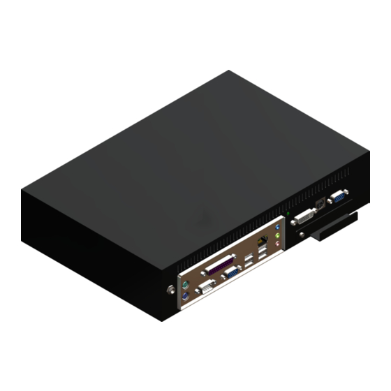
Page 9: Inputs And Outputs
Figure 2 shows the rear panel connectors of a AV-GM0AK3-S1 and Table 1 illustrates how you can connect video devices and display to the AV-GM0AK3-S1. - Page 10 Table 1: I/O Connectors Input Connector Video Source [1] DVI [2] VGA — with a DVI-to-VGA adapter (DVA01) [3] Component (YPbPr) — with a DVI-to-VGA adapter (DVA01) and a DVI-IN VGA-to-component breakout cable (VYPBA01) [4] 1x DVI + 1x VGA — with a DVI-to-DVI/VGA breakout cable (DDVY01) [5] 1x DVI + 1x Component (YPbPr) —...
-
Page 11: Chapter 2 Hardware Installation
Installation Procedures Unpacking Remove the AV-GM0AK3-S1 from the shipping container and examine it for any signs of shipping damage or missing items (check with package contents above). All shipping items should be saved if the product is to be moved or returned for service. Shipping unit back to dealers for service not in the original box may result in voiding warranty or additional cost. - Page 12 7. Connect a device equipped with composite video output to composite input of the AV-GM0AK3-S1. 8. Connect your computer with the AV-GM0AK3-S1 by a Mini USB cable and then install the software. 9. Plug in power adapter cable into 12V DC power jack. Please also noted that when AV-GM0AK3-S1 power adapter plug in, it will be boot up.
-
Page 13: System Requirement And Precautions
2. Before you click on the icon of the software, make sure you have secured the connection between your computer COM port and the AV-GM0AK3-S1, also switched on the AV-GM0AK3-S1 with green LED light. 3. The AV-GM0AK3-S1 has software control. To make sure all information shown in the software is synchronized with those in the device. -
Page 14: Instruction Of Software Connection
Instruction of Software Connection 1. Power up the AV-GM0AK3-S1 and you can see both red and green LEDs on the front panel blink. Make sure the serial port USB connection secure. 2. The first step after running the software is to automatically detect if the device responses correctly through USB port. -
Page 16: Instruction Of Software Operation
Instruction of Software Operation Menu File a. Device Linkage: This will synchronize the status or the AV-GM0AK3-S1 with the software, especially after IR commands sent. b. Data Table: It will show a dialog that will list the input and resolution data. - Page 17 Advance Firmware Update: It will show a dialog, that that update the firmware to the newest version. g. Resolution Parameter: It will show a dialog that for custom output resolution. Tree List Dialog a. Output Resolution and Type b. Layout Mode c.
- Page 18 a. Main channel’s input signal select and information. b. Sub channel’s input signal select and information. c. “Input Info.” Button: Update the current signal status. d. “SWAP” Button: Switch the input signal between the main and sub channel. e. “Color Balance” Button: Auto adjust the AD gain value.
- Page 19 The border control a. Size and Position b. Width c. Color Dialog 1. PAP control dialog: While you move the mouse’s cursor near the borders, in either red or blue, the icon of the cursor will change as the figure below. 2.
-
Page 20: Chapter 4 Troubleshooting
3. Serial port dialog: Please select the correct number of serial port. 4. Firmware Update dialog: It supports to update the firmware to the newest version. 5. Resolution Parameter dialog: It can be edited and saved the parameter of output resolution in device. - Page 21 Make sure all cables are in good working condition and properly No/ Erratic video connected to the AV-GM0AK3-S1 and displays. Configure the output video resolution so that it doesn’t excess the native resolution of the display. ( in this case, the message of “out of range”...
- Page 22 Limited Warranty The SELLER warrants the AV-GM0AK3-S1 Dual-View Video Processor Audio Path and RS-232 to be free from defects in the material and workmanship for 3 years from the date of purchase from the SELLER or an authorized dealer. Should this product fail to be in good working order...
-
Page 23: Appendix Supported Resolution
Appendix – Supported Resolution [DVI-IN] socket Supported Mode Resolution NTSC – 480i / 525i 720x240 @60Hz 832x624 @75Hz PAL– 576i / 625i 720x288 @50Hz VESA 1024x768 @60Hz PAL– 480p / 525p 720x483 @60Hz 1024x768 @60Hz PAL– 480p (16:9) 960x483 @60Hz VESA 1024x768 @70Hz PAL–... - Page 24 VESA 800x600 @56Hz VESA 800x600 @60Hz VESA 800x600 @72Hz VESA 800x600 @75Hz VESA 800x600 @85Hz...
- Page 25 [VGA-IN] socket Supported Mode Resolution 480p / 525p 720x483 @60Hz VESA 800x600 @56Hz 480p (16:9) 960x483 @60Hz VESA 800x600 @60Hz HDTV – 720p 1280x720 @50Hz VESA 800x600 @72Hz HDTV – 720p 1280x720 @60Hz VESA 800x600 @75Hz HDTV – 1080i 1920x1080 @30Hz VESA 800x600 @85Hz HDTV - 1080p...
Need help?
Do you have a question about the AV-GM0AK3-S1 and is the answer not in the manual?
Questions and answers