Table of Contents
Advertisement
Advertisement
Table of Contents

Related Manuals for Linear SWC


Summary of Contents for Linear SWC
- Page 1 SWR - SWC - SWD Swing Gate Operator Installation Guide Operator models contained in this manual conform to UL325 standard for use in Class I, II, III, and IV applications USA & Canada (800) 421-1587 & (800) 392-0123 (760) 438-7000 - Toll Free FAX (800) 468-1340 www.linearcorp.com...
-
Page 2: Table Of Contents
Stagger Delay Time ........15 LINEAR SWING GATE Auxiliary Relay Mode . -
Page 3: Pre-Installation Information
If any pages are missing or are unreadable, four single family dwellings with a common garage or parking area or you do not have the safety instructions, please call Linear at associated with these dwellings. 1-800-421-1587 to request additional copies. -
Page 4: Wiring Specifi Cations
Wiring Specifi cations MODEL SWR POWER WIRING MAXIMUM DISTANCE (FEET) VOLTS & HP WIRE GAUGE Refer to the following steps for details on power and SINGLE DUAL accessory wiring for the operator. 115 VOLTS WARNING 1/2-HP 1272 ALL AC ELECTRICAL CONNECTIONS TO THE POWER SOURCE AND 2022 1011 THE OPERATOR MUST BE MADE BY A LICENSED ELECTRICIAN... -
Page 5: Mounting Pad Installation
Mounting Pad Installation WARNING The operator is intended for installation only on gates used for The gate operator mounts bolted to a custom poured vehicles. Pedestrians must be supplied with a separate access concrete mounting pad. The pad supports the operator and opening. -
Page 6: Operator Preparation
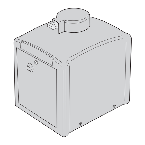
Operator Preparation GEAR REDUCER Vent Plug Installation In order to keep gear oil from spilling out during shipping, REMOVE THE gear reducers used in gate operators have either a solid SOLID PLUG WITH AN ALLEN plug, or a sealed vent plug, installed at the factory. WRENCH For operators with a solid plug, replace the solid plug with the vent plug provided (see Figure 2). -
Page 7: Choosing Good Harmonics
Gate Arm Installation (Cont.) GATES SHOWN OPEN Choosing Good Harmonics Good harmonics are necessary to minimize wear and tear on the operator. The gate will have smoother starts and stops GOOD when the arm is installed with good harmonics. Figure 5 HARMONICS HARMONICS! shows an example of good and bad arm harmonics. -
Page 8: Operator Setup
115 VAC WIRING GREEN - GROUND AC Power Connection BLACK - HOT All Linear gate operators are supplied with a power WHITE - NEUTRAL disconnect switch to turn on and off the power available to CONNECT AC POWER the operator (see Figure 9). Following wiring specifi cations... -
Page 9: Limit Cam Rough Adjustment
Operator Setup (Continued) LIMIT Limit Cam Rough Adjustment SWITCHES (2) RIGHT-HAND INSTALLATION The limit cams are not preset at the factory and must TOP CAM - OPEN LIMIT be adjusted for each installation. The limit switches are BOTTOM CAM - CLOSE LIMIT activated by two rotating limit cams attached to the drive shaft (see Figure 10). -
Page 10: Controller Features
Controller Features WHIP ANTENNA ANTENNA CONNECTOR OPERATION AND POWER PROGRAMMING OPERATION INDICATORS INDICATORS BUTTONS DISPLAY PROGRAMMING SOLAR BUTTONS PANEL TERMINALS INPUT POWER MOTOR TERMINALS BOARD COVER ACCESSORY POWER BATTERY TERMINALS TERMINALS RESET BUTTON PLUG-IN TERMINALS LOOP PRIMARY/ DETECTOR SECONDARY CONNECTORS COMM LINK TERMINALS SINGLE... -
Page 11: Indicator Descriptions
Indicator Descriptions INDICATOR DEFINITION INDICATION WHEN LIT INDICATION WHEN LIT DURING NORMAL OPERATION DURING PROGRAMMING OPERATION PROGRAMMING 24 VOLT INPUT LOW VOLTAGE AC POWER IS PRESENT POWER 24 VOLT DC LOW VOLTAGE DC POWER IS PRESENT ACCY POWER OPEN SIGNAL PRESENT FROM THE INTERNAL OPEN RECEIVER OR AN EXTERNAL DEVICE CONNECTED TO THE OPEN INPUT TERMINAL... -
Page 12: Terminal Descriptions
Terminal Descriptions TERMINAL GROUP FUNCTION AC N FACTORY CONNECTED TO 24 VAC FROM TRANSFORMER OR 24 VOLT INPUT 24 VDC FROM CONTINUOUS DUTY DC SUPPLY. DC - ACCESSORY POWER PROVIDES 24 VOLT DC POWER FOR ACCESSORIES. (.5A MAX) DC + RESET RESET BUTTON FACTORY CONNECTED TO THE CONTROLLER’S RESET BUTTON. -
Page 13: Operator Accessory Connections
Operator Accessory Connections 3-BUTTON STATION PHOTOEYE FOR REVERSE TELEPHONE ENTRY KEYPAD PHOTOEYE FOR CLOSE OBSTRUCTION KEYSWITCH FIRE ACCESS SWITCH SOLENOID LOCK EXTERNAL POWER PHOTOEYE FOR OPEN OBSTRUCTION SINGLE-CHANNEL RADIO RECEIVER MAGLOCK GATE EDGE SENSOR FOR REVERSE TWO-CHANNEL RADIO RECEIVER WARNING STROBE OR AUDIBLE SOUNDER CHANNEL #1 WIRELESS GATE EDGE SENSOR OPEN/CLOSE... -
Page 14: Basic Controller Programming
Basic Controller Programming Programming Overview PROGRAM The Controller can be programmed with various options for the operator. INDICATOR The programming fi elds are defi ned as “functions” that have “options”. DOWN To make setup easier for the installer, the Controller’s programming is divided into two groups: basic and advanced. -
Page 15: Run Alarm And Pre-Start Alarm
Basic Controller Programming (Cont.) Run Alarm and Pre-start Alarm FUNCTION OPTIONS RUN ALARM OFF The factory default is Run Alarm on and a 3-second Pre-start Alarm. The "RP" PRE-START ALARM OFF operator’s beeper will sound 3 seconds before the operator starts. The options are: RUN ALARM ON PRESS UP OR... -
Page 16: Advanced Controller Programming
Advanced Controller Programming Entering Advanced Programming Mode FUNCTION OPTIONS ADVANCED PROGRAMMING FUNCTIONS To access and program the Advanced Programming functions, for each "AD" WILL NOT BE DISPLAYED programming session, Advanced Programming must be enabled. ADVANCED PROGRAMMING OPTIONS After exiting programming, the Advanced Programming functions WILL BE DISPLAYED will be available on the programming display during the next programming session unless the operator has run 50 or more... -
Page 17: Stagger Delay Time
Advanced Controller Programming (Cont.) Stagger Delay Time FUNCTION OPTIONS STAGGER TIMER DISABLED This function is used in dual gate installations only. The factory "ST" default sets the Stagger Time to 0 seconds (OFF). The Stagger Time sets the delay for the Stagger Mode. The Stagger Delay Time can be set SET STAGGER DELAY VALUE 1 TO 99 SECONDS from 1-99 seconds. -
Page 18: Shadow Loop Open Prevention
Advanced Controller Programming (Cont.) Shadow Loop Open Prevention FUNCTION OPTIONS STANDARD OPERATION If the shadow loop is triggered, it always prevents the gate from closing if "SP" SHADOW LOOP INHIBITS CLOSING ONLY the Auto Close Timer activates or a CLOSE command is given while the gate is at the full open position. -
Page 19: Soft Start/Stop Duration
Advanced Controller Programming (Cont.) Soft Start/Stop Duration FUNCTION OPTIONS SOFT START DISABLED This function is only used with DC swing gate Model SWD. This "SS" function causes the operator to start and stop the DC motor slowly reducing gate wear and tear (at the full open or closed positions only). SET SOFT START DURATION TIME FROM 1 TO 10 SECONDS The factory default sets the Soft Start/Stop Duration to 3 seconds. -
Page 20: Mid-Travel Stop Position
Advanced Controller Programming (Cont.) Mid-travel Stop Position FUNCTION OPTIONS MID-TRAVEL STOP DISABLED The Controller can be programmed so the gate will stop at a mid-travel "MT" (GATE RUNS FULL TRAVEL) point instead of fully opening. This can be useful in installations where a large gate, that takes a long time to open and close fully, only needs to SET LENGTH OF OPENING TIME FROM 1 TO 99 SECONDS... -
Page 21: Radio Enable
Advanced Controller Programming (Cont.) Radio Enable FUNCTION OPTIONS The Controller contains a built-in MegaCode radio receiver to allow "RA" INTERNAL RADIO RECEIVER DISABLED ® activation from up to 40 access control transmitters and two Model MGT (gate edge) transmitters. The factory default enables the internal radio INTERNAL RADIO RECEIVER ENABLED receiver. -
Page 22: Loop Layout Illustration
Loop Layout Illustration - 20 - SWR • SWC • SWD Swing Gate Operator Installation Guide 227965 Revision X22 8-11-2011... -
Page 23: Safety Edge Layout Illustration
Safety Edge Layout Illustration - 21 - SWR • SWC • SWD Swing Gate Operator Installation Guide 227965 Revision X22 8-11-2011... -
Page 24: Photoeye Installation Illustration
Photoeye Installation Illustration - 22 - SWR • SWC • SWD Swing Gate Operator Installation Guide 227965 Revision X22 8-11-2011... -
Page 25: Dual Gate Installations
Dual Gate Installations Gate Operation Two operators can be used in dual gate installations. The operators Open Button communicate with each other through the 3-wire COMM LINK terminals. Opens the gate. If the Controller is programmed to stop opening the gate at mid-travel, a constant press of the OPEN button will override the When one operator activates, the COMM LINK connection signals the other operator to activate. -
Page 26: Operation Indications
Operation Indications MGT Obstacle Transmitter Trouble If any MGT transmitters are used with the operator, their During normal operation, the Controller’s displays will supervision feature will alert the Controller if there is any indicate current operating conditions and status. trouble with the transmitter. MGT transmitters send hourly Power-up Display status reports and will send low battery reports when the transmitter has a low battery. -
Page 27: Troubleshooting
How to Order Replacement Parts Use the part numbers listed on the following pages. Contact your local Linear dealer or distributor to order parts. 1. Supply the model number and serial number of your operator. 2. Specify the quantity of pieces needed and order by part number and name of part. -
Page 28: Model Swr Exploded View
Model SWR Exploded View REF. # PART # DESCRIPTION MODEL SWR MECHANICAL PARTS LIST 2510-422 115 VAC Power Box Assembly REF. # PART # DESCRIPTION 2510-430 230 VAC Power Box Assembly 2300-925-BEIGE Operator Cover, Tan 2500-2411 Power Switch Only, 115 VAC and 230 VAC 2300-925-BLACK Operator Cover, Black 2500-2413... -
Page 29: Model Swc Exploded View
Model SWC Exploded View REF. # PART # DESCRIPTION MODEL SWC MECHANICAL PARTS LIST 2200-016 Moisture Seal REF. # PART # DESCRIPTION 2200-274 Pillow Block Bearing, 1” diameter 2300-925-BEIGE Operator Cover, Tan 2200-376 Sprocket, 40-B-36, 1” bore (for 1/2 and 3/4 HP) 2300-925-BLACK Operator Cover, Black 2200-959... -
Page 30: Model Swd Exploded View
Model SWD Exploded View REF. # PART # DESCRIPTION MODEL SWD MECHANICAL PARTS LIST 2200-673 #40 Chain, 21 Links REF. # PART # DESCRIPTION 2200-006 #40 Master Link 2300-925-BEIGE Operator Cover, Tan 2100-1748 Limit Cam 2300-925-BLACK Operator Cover, Black 2200-015 Shaft Collar, 1”... -
Page 31: Swr, Swc, Swd Gate Arm Assembly Exploded View
SWR, SWC, SWD Gate Arm Assembly Exploded View GATE ARM ASSEMBLY MECHANICAL PARTS LIST REF. # PART # DESCRIPTION 2120-493 Complete Arm Assembly 2100-2068-PLT Threaded Crank Block 2100-2069-PLT V-Block for Crank Block 2100-2067 Crank Extension Solid Bar 2110-810 Crank Extension and Spacer Assembly 2100-1924-PLT Overtravel Stop 2300-969... -
Page 32: Model Swd Maintenance
Model SWD Maintenance Battery Maintenance DC Motor Brush Replacement The gel-cell batteries in this operator require no routine Brushes should be inspected every 100,000 cycles or maintenance. For assured continued performance, they yearly, whichever comes fi rst. The motor has two brushes, should be replaced every year. -
Page 33: Preventative Maintenance
General 2. For operators with V-belts, inspect for wear and replace Linear gate operators are designed for many years of as necessary. Check for proper tension and adjust if trouble-free operation and, under recommended operating required. Check all pulley setscrews for tightness and conditions, will require only minimal maintenance. -
Page 34: Gate Operator Installation Checklist
Gate Operator Installation Checklist INSTALLER CUSTOMER ❑ ❑ The gate has been checked to make sure it is level and moves freely in both directions. ❑ ❑ Potential pinch areas have been guarded so as to be inaccessible OR have contact and/or non-contact obstruction sensing devices installed.
Need help?
Do you have a question about the SWC and is the answer not in the manual?
Questions and answers