Table of Contents
Advertisement
Quick Links
NOTE: Read the entire instruction manual before starting the
installation.
This symbol
indicates a change since the last issue.
SAFETY CONSIDERATIONS .....................................................1
Introduction ....................................................................................2
Receiving and Installation..............................................................2
Check Equipment......................................................................2
IDENTIFY UNIT ................................................................2
INSPECT SHIPMENT ........................................................2
Provide Unit Support ................................................................2
ROOF CURB.......................................................................2
SLAB MOUNT ...................................................................2
GROUND MOUNT ............................................................2
Provide Clearances....................................................................2
Rig and Place Unit....................................................................2
INSPECTION ......................................................................3
INSTALLATION ................................................................3
Select and Install Ductwork .....................................................5
DOWNFLOW (VERTICAL) DISCHARGE UNITS.........7
Provide for Condensate Disposal .............................................7
Install Electrical Connections...................................................8
HIGH-VOLTAGE CONNECTIONS..................................9
ROUTING POWER LEADS INTO UNIT ........................9
ROUTING CONTROL POWER WIRES (24-V) ..............9
Easy Select™-604B ........................................................10
604B Sequence Of Operation ...........................................17
PRE-START-UP ..........................................................................18
START-UP ...................................................................................18
604B: Start-Up ........................................................................18
Check for Refrigerant Leaks ..................................................19
Start-Up Adjustments..............................................................19
ERATION ..........................................................................19
CHARGE ...........................................................................19
REFRIGERANT CHARGE ..............................................20
NO CHARGE ....................................................................20
LOW CHARGE COOLING .............................................20
TO USE COOLING CHARGING CHARTS ..................20
MENTS ..............................................................................21
Defrost Control .......................................................................21
Quiet Shift..........................................................................21
Defrost................................................................................22
MAINTENANCE.........................................................................23
Air Filter..................................................................................24
Indoor Blower and Motor.......................................................24
Outdoor Fan ............................................................................24
Electrical Controls and Wiring...............................................25
Installation, Start-Up,
and Service Instructions
604B 024-060
SINGLE-PACKAGED HEAT PUMP UNITS
WITH PURON® (R-410A) REFRIGERANT
Cancels: II 604B.24.2
Refrigerant Circuit ..................................................................25
Indoor Airflow ........................................................................25
Metering Devices-TXV & Accurater Piston.........................25
Pressure Switches....................................................................25
Loss of Charge Switch ...........................................................25
High-Pressure Switch..............................................................25
Copeland Scroll Compressor (Puron Refrigerant).................25
Refrigerant System..................................................................26
Refrigerant .........................................................................26
Compressor Oil..................................................................26
Liquid Line Filter Drier ....................................................26
Puron (R-410A) Refrigerant Charging .............................26
System Information.................................................................26
Loss of Charge Switch ......................................................26
Check Defrost Thermostat ................................................26
TROUBLESHOOTING ...............................................................26
Start-Up Checklist ........................................................................26
NOTE TO INSTALLER - READ THESE INSTRUCTIONS
CAREFULLY AND COMPLETELY before installing this unit.
Also, make sure the Owner's Manual and Service Instructions are
left with the unit after installation.
SAFETY CONSIDERATIONS
Installation and servicing of air-conditioning equipment can be
hazardous due to system pressure and electrical components. Only
trained and qualified personnel should install, repair, or service
air-conditioning equipment.
-1-
II 604B.24.3
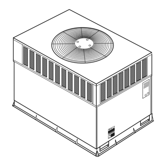
Fig. 1-Unit 604B
12-03
C99064
Advertisement
Table of Contents

Related Manuals for Bryant 604B 024–060


Summary of Contents for Bryant 604B 024–060
-
Page 1: Table Of Contents
Installation, Start-Up, and Service Instructions 604B 024–060 SINGLE-PACKAGED HEAT PUMP UNITS WITH PURON® (R-410A) REFRIGERANT Cancels: II 604B.24.2 II 604B.24.3 12–03 NOTE: Read the entire instruction manual before starting the Refrigerant Circuit ..............25 installation. Indoor Airflow ................25 Metering Devices–TXV & Accurater Piston......25 This symbol indicates a change since the last issue. -
Page 2: Introduction
Check all items against shipping list. Immediately notify the available for all brazing operations. nearest Bryant Air Conditioning office if any item is missing. To prevent loss or damage, leave all parts in original packages until WARNING: Improper installation, adjustment, alter- installation. -
Page 3: Inspection
Required Clearance for Operation and Service C00160 CENTER OF GRAVITY UNIT HEIGHT UNIT WEIGHT IN. (MM) UNIT ELECTRICAL CHARACTERISTICS IN. (MM) ”A” 604B024 208/230-1-60 39.02 (991.1) 20.0 (508.0) 19.3 (489.0) 17.6 (447.0) 604B030 208/230-1-60 39.02 (991.1) 20.0 (508.0) 19.3 (489.0) 17.6 (447.0) 604B036 208/230-1-60,208/230-3-60... - Page 4 C00161 CENTER OF GRAVITY UNIT HEIGHT UNIT WEIGHT IN. (MM) UNIT ELECTRICAL CHARACTERISTICS IN. (MM) ”A” 604B042 208/230-1-60, 208/230-3-60 42.98 (1091.7) 21 (533.4) 20.5 (520.7) 16.6 (421.6) 604B048 208/230-1-60, 208/230-3-60 44.98 (1142.5) 19.5 (495.3) 21.3 (539.8) 18.0 (457.2) 604B060 208/230-1-60, 208/230-3-60 46.98 (1193.3) 21.0 (533.4) 20.0 (508.0)
-
Page 5: Select And Install Ductwork
C00071 CORNER WEIGHTS (SMALL CABINET) CORNER WEIGHTS (LARGE CABINET) Unit Unit Total Weight Total Weight Corner Weight 1 Corner Weight 1 Corner Weight 2 Corner Weight 2 Corner Weight 3 Corner Weight 3 Corner Weight 4 Corner Weight 4 Fig. 4—Corner Weights 7. - Page 6 HVAC unit HVAC unit base base Gask eting inner flange* Scre w Scre w Gask eting (NO TE A) inner flange* (NO TE A) *Gask eting *Gask eting outer flange outer flange Wood nailer* Wood nailer* Flashing field Flashing field supplied supplied Roofcurb*...
-
Page 7: Converting Horizontal Discharge Units To Downflow (Vertical) Discharge Units
MAXIMUM ALLOWABLE DIFFERENCE (in.) C99065 Fig. 6—Unit Leveling Tolerances OPTIONAL OPTIONAL RETURN SUPPLY OPENING OPENING 2" EVAP. COIL COND. COIL C99096 Fig. 7—Slab Mounting Detail HANDHOLD HOOK FEED C99067 Fig. 8—Threading Belt 5. Secure all ducts to building structure. Flash, weatherproof, 4. -
Page 8: Install Electrical Connections
914-137" (36"-54") “A” “B” DETAIL A SCALE 0.250 TIGHTEN STRAPPING SECURELY WITH TENSION BUCKLE INSTALL SAFETY STRAPS TO RIGGING CLEVIS AT 4 RIGGING BRACKETS PLACE RIGGING BRACKET ASSEMBLY IN 4 RIGGING HOLES AND INSTALL TIE DOWN STRAP AROUND PERIMETER OF UNIT AND THROUGH SPACE IN BRACKET ASSEMBLY SEE DETAIL A C99075... -
Page 9: High-Voltage Connections
TABLE 1—PHYSICAL DATA—UNIT 604B UNIT SIZE 604B024 604B030 604B036 604B042 604B048 604B060 NOMINAL CAPACITY (ton) OPERATING WEIGHT (lb.) COMPRESSOR QUANTITY TYPE SCROLL COMPRESSOR REFRIGERANT R-410A Indoor-TXV REFRIGERANT METERING DEVICE Outdoor-Accurater Refrigerant (R-410A) Quantity (lb.) 10.8 11.5 14.0 METERING DEVICE 0.038 (Left OD Coil) 0.042 (Left OD Coil) ORIFICE OD (in.) 0.035 (2) -
Page 10: Easy Select™-604B
INDOOR THERMOSTAT RETURN FROM TOP COVER POWER SOURCE DISCONNECT PER NEC* *NEC - NATIONAL ELECTRICAL CODE C00063 Fig. 10—Typical Installation Duct Covers C00092 Fig. 11—604B with Duct Covers On E. Easy Select™—604B Installer must select the auxiliary heat airflow approved for application with kW size heater installed. - Page 11 1” (25mm) MIN. TRAP OUTLET 2” (50mm) MIN. C99013 Fig. 12—Condensate Trap TABLE 3—ELECTRICAL DATA—604B VOLTAGE UNIT 604B COMPRESSOR ODFM IDFM ELECTRIC HEAT SINGLE POINT POWER SUPPLY V-PH-HZ RANGE SIZE Nominal Kw* UNIT MCA MAX FUSE OR CKT BKR MOCP 22.1/22.1 30/30 —...
- Page 12 EXAMPLE: Supply voltage is 230-3-60. AB = 228 v LEGEND BC = 231 v AC = 227 v — Full Load Amps — Locked Rotor Amps 228 + 231 + 227 ® Average Voltage = -- Minimum Circuit Amps MOCP — Maximum Overcurrent Protection —...
- Page 13 C03005 Fig. 14—Wiring Schematics-604B Single Phase —13—...
- Page 14 C03006 Fig. 15—Wiring Schematics-604B Three Phase —14—...
- Page 15 HIGH VOLTAGE POWER LEADS POWER (SEE UNIT WIRING SUPPLY LABEL) FIELD-SUPPLIED FUSED DISCONNECT CONTROL BOX BLK(DH) DHUM YEL(Y) THERMOSTAT GRN(G) (TYPICAL) LOW-VOLTAGE POWER LEADS RED(R) (SEE UNIT BRN(C) WIRING LABEL) WHI(W1) GRA(W2) ORN(0) SPLICE BOX LEGEND Field Control-Voltage Wiring Field High-Voltage Wiring C01028 Fig.
- Page 16 deliver 100 percent airflow reducing the cold blow sensation at start up in heating and allow- TRANSFORMER CONTAINS A MANUAL RESET OVERCURRENT PROTECTOR ing the indoor coil to more quickly reach wet coil operating conditions in cooling. IT WILL NOT AUTOMATICALLY RESET (b.) A no blower off delay eliminates cold blow DISCONNECT POWER AND INSTALL which may be associated with running the...
-
Page 17: 604B Sequence Of Operation
the motor will deliver airflow at the full cooling or EASY SELECT BOARD TERMINAL cooling plus dehumidify mode requested value. If BLOCK circuit R to G is open (0–v.) for super dehumidify mode, the motor delivers reduced airflow to maxi- mize the humidity removal of the system while minimizing over cooling. -
Page 18: Pre-Start-Up
PRE-START-UP 6. Each unit system has 2 Schrader-type ports, one low-side Schrader fitting located on the suction line, and one WARNING: Failure to observe the following warnings high-side Schrader fitting located on the compressor dis- could result in serious personal injury or death: charge line. -
Page 19: Check For Refrigerant Leaks
INDOOR COIL OUTDOOR COIL TXV in Metering Position HP S Bypass LEGEND Position HPS – High Pressure Switch LCS – Loss of Charge Switch Accurater ® Metering De vice Arrow indicates direction of flo w C03011 Fig. 24—Typical Heat Pump Operation, Cooling Mode between thermostat terminal R to terminals Y and G. -
Page 20: Refrigerant Charge
INDOOR COIL OUTDOOR COIL TXV in Bypass Position HP S Metering Position LEGEND HPS – High Pressure Switch LCS – Loss of Charge Switch Accurater ® Metering De vice Arrow indicates direction of flo w C03012 Fig. 25—Typical Heat Pump Operation, Heating Mode TABLE 4A—604B COOLING &... -
Page 21: Indoor Airflow And Airflow Adjustments
TABLE 4B—604B COOLING & HEATING DRY COIL ECM AIRFLOW LARGE CABINET CFM ADJUST LO PIN NOM PIN HI PIN PIN SELECT UNIT SIZE EXTERNAL STATIC 0.1–1.0 0.1–1.0 0.1–1.0 PRESSURE RANGE COOLING † 1100 1225 1410 COOLING 1125 DEHUMIDIFY HEAT PUMP 1100 1265 COMFORT... -
Page 22: Defrost
ELECTRIC HEAT PRESSURE DROP TABLE LARGE CABINET: 042-060 1100 1200 1300 1400 1500 1600 1700 1800 1900 2000 2100 2200 2300 2400 2500 5 kw 0.00 0.00 0.00 0.01 0.02 0.03 0.04 0.05 0.06 0.07 0.08 0.09 0.10 0.11 0.12 7.5 kw 0.00 0.00... -
Page 23: Maintenance
Required Subcooling oF (oC) Required Liquid Line Temperature for a Specific Subcooling (R-410A) Outdoor Ambient Temperature Required Subcooling ( Required Subcooling ( Model Size 75 (24) 82 (28) 85 (29) 95 (35) 105 (41) Pressure Pressure (kPa) (psig) 10.3 ( 5.7 ) 9.8 ( 5.4 ) 9.4 ( 5.2 ) 9 ( 5 ) -
Page 24: Air Filter
CESO130076–00 Speedup Quiet Defrost interval Pins Shift DIP switches A99442 Fig. 28—Defrost Control I. AIR FILTER Straighten bent fins with a fin comb. If coated with dirt or lint, clean the coils with a vacuum cleaner, using the soft brush IMPORTANT: Never operate the unit without a suitable air filter attachment. -
Page 25: Electrical Controls And Wiring
5. When replacing fan blade, position blade so that the hub is VIII. METERING DEVICES–TXV & ACCURATER PISTON 1/8 in. away from the motor end (1/8 in. of motor shaft will This unit uses 2 types of metering devices. The outdoor metering be visible). -
Page 26: Refrigerant System
need for a cycle protector. The pressure relief port is a safety removing a filter drier, use a tubing cutter to cut the drier from the device, designed to protect against extreme high pressure. The system. Do not unsweat a filter drier from the system. Heat relief port has an operating range between 550 and 625 psi from unsweating will release moisture and contaminants from differential pressure. - Page 27 HEAT PUMP WITH PURON REFRIGERATION SECTION-QUICK REFERENCE GUIDE Puron refrigerant operates at 50-70 percent higher pressures than R-22. Be sure that servicing equipment and replacement components are de- signed to operate with Puron. Puron refrigerant cylinders are rose colored. • Puron refrigerant cylinders manufactured prior to March 1, 1999, have a dip tube that allows liquid to flow out of cylinder in upright position. Cylinders manufactured March 1, 1999 and later DO NOT have a dip tube and MUST be positioned upside down to allow liquid to flow.
- Page 28 QUICK REFERENCE GUIDE SET-UP INSTRUCTIONS FOR WARMER HEATING TEMPERATURES AND SUPER HUMIDITY CONTROL IN COOLING EASY SELECT BOARD 1. Configuration Taps 9 PIN CONNECTOR (See Installation Instructions, for detailed description.) ICM PRINTED CIRCUIT BOARD A. AUX HEAT - Set for heater size (Ex: 0-10 for 10 kw) B.
- Page 29 TABLE 7—TROUBLESHOOTING CHART SYMPTOM CAUSE REMEDY Power Failure Call power company Fuse blown or circuit breaker tripped Replace fuse or reset circuit breaker Defective thermostat, contactor, transformer, control relay, defrost board, or high pressure or loss- Replace component of-charge/low pressure switch Compressor and outdoor fan Insufficient line voltage Determine cause and correct...
- Page 30 TABLE 7—TROUBLESHOOTING CHART (CONT’D) SYMPTOM CAUSE REMEDY Low refrigerant charge Check for leaks, repair and recharge Head pressure too low Restriction in liquid tube Remove restriction (Cool) High Heat load Check for source and eliminate Excessive suction pressure Reversing valve hung up or leaking internally Replace valve Refrigerant overcharged Recover excess refrigerant...
- Page 31 START-UP CHECKLIST (Remove and Store in Job File) I. Preliminary Information MODEL NO.:_________________________________ SERIAL NO.:__________________________________ DATE:_______________________________________ TECHNICIAN:_________________________________ II. PRE-START-UP (Insert checkmark in box as each item is completed) ( ) VERIFY THAT ALL PACKING MATERIALS HAVE BEEN REMOVED FROM UNIT ( ) REMOVE ALL SHIPPING HOLD DOWN BOLTS AND BRACKETS PER INSTALLATION INSTRUCTIONS ( ) CHECK ALL ELECTRICAL CONNECTIONS AND TERMINALS FOR TIGHTNESS ( ) CHECK GAS PIPING FOR LEAKS (WHERE APPLICABLE)
- Page 32 © 2003 Bryant Heating & Cooling Systems 7310 W. Morris St. Indianapolis, IN 46231 —32— Printed in U.S.A. ii604b243 Catalog No. 5360-404...
Need help?
Do you have a question about the 604B 024–060 and is the answer not in the manual?
Questions and answers