Table of Contents
Advertisement
Advertisement
Table of Contents

Related Manuals for Baumatic B46SS


Summary of Contents for Baumatic B46SS
- Page 1 B46SS/BG60SS/B60.1SS/ BT61SS/BT60.2SS 60 cm 4 Burner gas hob...
- Page 2 User Manual for your Baumatic B46SS 4 Burner gas hob BG60BL/SS/W 4 Burner gas hob B60.1SS 4 Burner gas hob with cast iron pan stands BT61SS 4 Burner gas hob with cast iron pan stands BT60.2SS 4 Burner gas hob with cast iron pan...
-
Page 3: Table Of Contents
Contents Environmental note Important safety information 5 – 7 Specifications 8 – 14 B46SS BG60SS B60.1SS BT61SS BT60.2SS Electrical details Gas details Gas hob surface layout Using the gas hob 15 - 17 Before first use Switching the hob on Push button ignition 15 –... -
Page 4: Environmental Note
Environmental note o The packaging materials that Baumatic uses are environmentally friendly and can be recycled. o Please discard all packaging material with due regard for the environment. -
Page 5: Important Safety Information
No modifications to the appliance are permitted by Baumatic Ltd. o You should not store or place flammable or highly flammable liquids/materials on top of or near the appliance. Items made... - Page 6 Safety o Baumatic strongly recommend that babies and young children are prevented from being near to the appliance and not allowe to touch the applianc e at any time. During and after use, all surfaces will be hot. o If it is necessary for younger family members to be in the...
- Page 7 If the appliance is being used in a Leisure Accommodation Vehicle, the requirements of N 721 MUST be followed. o Baumatic Ltd. DO NOT recommend that this appliance is installed on any type of marine vessel. Declaration of conformity This appliance complies with the following European Directives: -73/23/EEC dated 19/02/1973 Low Voltage Directive.
-
Page 8: Specifications
Specifications B46SS Product dimensions: Aperture dimensions: Height: 500 mm Height: 480 mm Width: 585 mm Width: 560 mm Depth: 35 mm Product specifications: o 1 x 3.00 kW Rapid burner o 2 x 1.75 kW Semi-rapid burners o 1 x 1.00 kW Auxiliary burner o Side control operation o Enamelled pan stands o Push button ignition... -
Page 9: Bg60Ss
BG60SS Product dimensions: Aperture dimensions: Height: 500 mm Height: 480 mm Width: 585 mm Width: 560 mm Depth: 35 mm o 1 x 3.00 kW rapid burner o 2 x 1.75 kW semi-rapid burners o 1 x 1.00 kW auxiliary burner o Side control operation o Push button ignition o Enamelled pan stands... -
Page 10: B60.1Ss
B60.1SS Product dimensions: Aperture dimensions: Height: 500 mm Height: 480 mm Width: 585 mm Width: 560 mm Depth: 35 mm o 1 x 3.00 kW rapid burner o 2 x 1.75 kW semi-rapid burners o 1 x 1.00 kW auxiliary burner o Side control operation o Push button ignition o Heavy duty cast iron pan stands... -
Page 11: Bt61Ss
BT61SS Product dimensions: Aperture dimensions: Height: 500 mm Height: 480 mm Width: 585 mm Width: 560 mm Depth: 35 mm o 1 x 3.30 kW triple crown (wok) burner o 2 x 1.75 kW semi-rapid burners o 1 x 1.00 kW auxiliary burner o Side control operation o Push button ignition o Heavy duty cast iron pan stands... -
Page 12: Bt60.2Ss
BT60.2SS Product dimensions: Aperture dimensions: Height: 500 mm Height: 480 mm Width: 585 mm Width: 560 mm Depth: 35 mm o 1 x 3.00 kW rapid burner o 2 x 1.75 kW semi-rapid burners o 1 x 1.00 kW auxiliary burner o Front control operation o Automatic ignition o Heavy duty cast iron pan stands... -
Page 13: Electrical Details
Electrical details (all models) Rated Voltage: 230 Vac 50 Hz Supply Connection: 3 A (double pole switched fused outlet with 3mm contact gap) Max Rated Inputs: 0.008 to 0.02 kW (depending on model) Mains Supply Lead: 3 core x 0.75mm² Gas details (all models) Connection: Rp ½... -
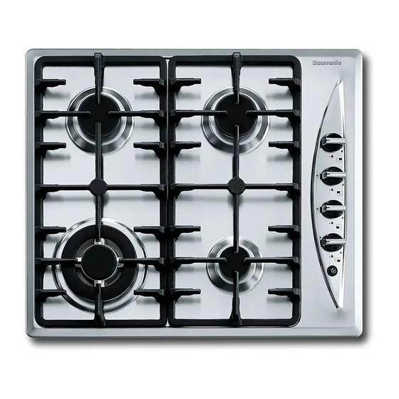
Page 14: Gas Hob Surface Layout
Gas hob surface layout B46SS/B60.1SS/BG60 BT61SS BT60.2SS... -
Page 15: Using The Gas Hob
Using the gas hob Before first use IMPORTANT: You should clean the hob surface (see “Cleaning and maintenance” section). Switching the hob on The following symbols will appear on the control panel, next to each control knob: Black circle: gas off Large flame: maximum setting Small flame: minimum setting o The minimum setting is at the end of the anti-clockwise rotation... -
Page 16: Automatic Ignition (Bt60.2Ss)
o To regulate the flame, you should continue turning the control knob anti-clockwise until the flame is at a suitable level. The operating position MUST be at a position between the maximum and minimum position. o To turn the burner off, turn the control knob fully clockwise to the gas off position. -
Page 17: Cleaning
o The burner flame must never extend beyond the diametre of the pan. o Use flat bottomed pans only o When possible, keep a lid on the pan whilst cooking. o Cook vegetables with as little water as possible, to reduce cooking times. -
Page 18: After Each Use
After each use o Remove the pan stands and wipe the appliance over with a soft, damp cloth that has been put into warm soapy water. The cloth should be wrung out after being taken out of the soapy water. o Dry the appliance by rubbing the surface with a soft, clean cloth. -
Page 19: Installation
IEE Wiring Regulations o Electricity at Work Regulations BS 6172 o Installation of Domestic Gas Cooking Appliances (if necessary, BS 5482 Installation of Domestic LPG Appliances) o BS 5440 Installation of Flues and Ventilation for Gas Appliances o Baumatic Ltd Installation Instructions... -
Page 20: Positioning
Positioning The adjacent furniture must be able to withstand a minimum temperature rise of 85°C above the ambient temperature of the room it is located in, during periods of use. o This appliance can be located in a kitchen, a kitchen diner or a bed sitting room. -
Page 21: Unpacking The Appliance
1 x Baumatic hob 2 x Pan supports 4 x Burner assemblies 1 x Installation and instruction manual 1 x Baumatic guarantee card 4 x Fixing screws 4 x Clamps 1 x Sealing strip 4 x LPG jets 1 x Self-adhesive label for amending the Gas Category on the appliance’s rating plate (required if the LPG conversion kit is used). - Page 22 o Carefully turn the hob upside down and place it on a cushioned mat. o Apply the sealing strip (A) provided around the edge of the appliance. o The protective covering must be removed from both sides. o Do not leave a gap in the sealing agent or overlap the thickness. o IMPORTANT: Do not use a silicon sealant to seal the appliance against the aperture.
-
Page 23: Gas Connection
Conversion for use on LPG and other gases must only be undertaken by a qualified person. For information on the use of other gases, please contact the Baumatic Advice Line. o The cooker must be installed by a qualified person, in... -
Page 24: Ventilation Requirements
Ventilation requirements o The room containing the cooker should have an air supply in accordance with the current edition of BS 5440: Part 2: o The room must have opening windows or equivalent; some rooms may also require a permanent vent. o If the room has a volume between 5 and 10m³, it will require an air vent of 50cm²... -
Page 25: Gas Safety (Installation And Use) Regulations
Gas Safety (Installation and Use) Regulations IMPORTANT: The appliance MUST be connected to the gas supply by use of a ½ BSP Elbow, seal, copper pipe and an isolation tap fitted in an easily accessible position. o It is the law that all gas appliances are installed by competent persons in accordance with the current edition of the Gas Safety Installation and Use Regulations. -
Page 26: Gas Adjustment (Conversion To Lpg)
Gas adjustment (Conversion to LPG) All work must be carried out by a CORGI registered engineer. IMPORTANT: Always isolate the hob from the electricity supply before changing the injectors and/or adjusting the minimum flow of the burners. o Remove the pan-stands, burners and flame spreaders (A). -
Page 27: Minimum Flow Adjustment For Hob Gas Taps
o IMPORTANT: The minimum flow adjustment process must be completed before the appliance is next used. Minimum flow adjustment for hob gas taps. All work must be carried out by a CORGI registered engineer. IMPORTANT: Always isolate the hob from the electricity supply before changing the injectors and/or adjusting the minimum flow of the burners. -
Page 28: Gas Tap Maintenance
Gas tap maintenance These maintenance operations MUST ONLY be carried out by a CORGI registered engineer. IMPORTANT: Before carrying out any maintenance operations, disconnect the appliance from the gas and electricity supplies. If a gas tap becomes stiff to operate, then you should proceed as follows: o Remove the control knobs, pan supports, burners, hob fixing screws and clamps. -
Page 29: Electrical Connection
Replacing the mains supply cable If the mains supply cable is damaged, then it must be replaced by an appropriate replacement which can be obtained from the Baumatic Spares Department. The mains supply cable should be replaced in accordance with the following instructions: o Switch the appliance off at the control switch. -
Page 30: My Appliance Isn't Working Correctly
Or any installation other than the one specified by Baumatic Ltd. has been completed. Please refer to the conditions of guarantee that appear on the... -
Page 31: Contact Details
Czech Republic United Kingdom Baumatic CR spol s.r.o. Baumatic Ltd., Amperova 495 Baumatic Buildings, 46215, Librec 6 Bennet Road, Czech Republic Reading, Berkshire RG2 0QX +420 800 185 263 United Kingdom www.baumatic.cz Sales Telephone (0118) 933 6900 Slovak Republic Sales Fax Baumatic Slovakia, s.r.o.
Need help?
Do you have a question about the B46SS and is the answer not in the manual?
Questions and answers