Table of Contents
Advertisement
Available languages
Available languages
Advertisement
Table of Contents

Subscribe to Our Youtube Channel
Related Manuals for ECS 661GX-M7


Summary of Contents for ECS 661GX-M7
- Page 3 Preface Copyright This publication, including all photographs, illustrations and software, is protected under international copyright laws, with all rights reserved. Neither this manual, nor any of the material contained herein, may be reproduced without written consent of the author. Version 3.0 Disclaimer The information in this document is subject to change without notice.
-
Page 4: Declaration Of Conformity
Declaration of Conformity This device complies with part 15 of the FCC rules. Operation is subject to the following conditions: • This device may not cause harmful interference, and • This device must accept any interference received, including interference that may cause undesired operation Canadian Department of Communications This class B digital apparatus meets all requirements of the Canadian Interference-causing Equipment Regulations. -
Page 5: Table Of Contents
T T T T T ABLE OF CONTENTS ABLE OF CONTENTS ABLE OF CONTENTS ABLE OF CONTENTS ABLE OF CONTENTS Preface Chapter 1 Introducing the Motherboard Introduction....................1 Feature......................2 Motherboard Components................4 Chapter 2 7 7 7 7 7 Installing the Motherboard Safety Precautions..................7 Choosing a Computer Case...............7 Installing the Motherboard in a Case............7... - Page 6 Integrated Peripherals..............36 Power Management Setup............39 PNP/PCI Configurations.............41 PC Health Status................42 Frequency/Voltage Control............43 Load Fail-Safe Defaults..............44 Load Optimized Defaults.............44 Set Password................44 Save & Exit Setup Option.............44 Exit Without Saving..............45 Chapter 4 47 47 47 47 47 Using the Motherboard Software About the Software CD-ROM..............47 Auto-installing under Windows 98/ME/2000/XP........47 Running Setup................48 Manual Installation..................50...
-
Page 7: Introducing The Motherboard
Chapter 1 Introducing the Motherboard Introduction Thank you for choosing the 661GX-M7 motherboard. This motherboard is a high perfor- mance, enhanced function motherboard that supports LGA775 Socket for latest Pentium 4/ Celeron Processors. The motherboard incorporates the SiS661GX Northbridge (NB) and SiS964 Southbridge (SB) chipsets. -
Page 8: Feature
Feature Processor This motherboard uses an LGA775 type of Pentium 4 that carries the following fea- tures: • Accommodates Intel P4/Celeron processors • Supports a system bus (FSB) of 533MHz • Supports “Hyper-Threading” technology CPU “Hyper-Threading” technology enables the operating system into thinking it’s hooked up to two processors, allowing two threads to be run in parallel, both on separate “logical”... - Page 9 Audio • Compliant with the AC’97 V2.3 CODEC • Supports 6-channel audio CODEC designed for PC multimedia systems • Provides three analog line-level stereo inputs with 5-bit volume control: LINE-IN, CD, AUX • Support S/PDIF output function Expansion Options The motherboard comes with the following expansion options: •...
-
Page 10: Motherboard Components
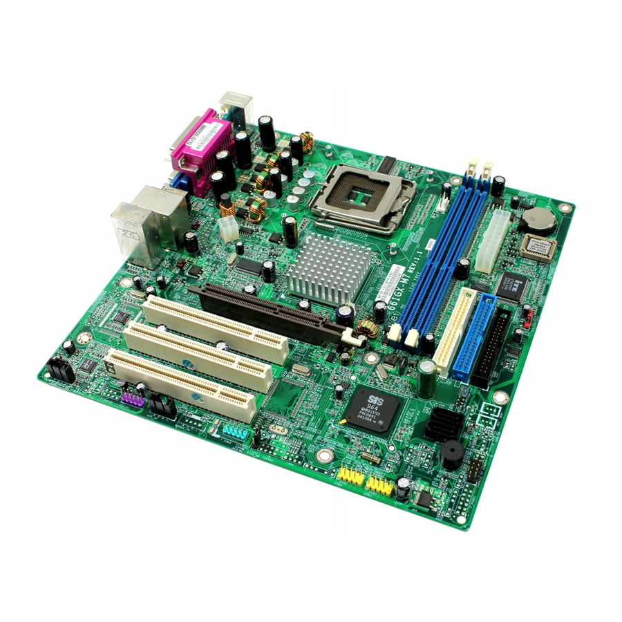
Motherboard Components Introducing the Motherboard... - Page 11 Table of Motherboard Components LABEL COMPONENT 1 CPU LGA775 socket for Pentium 4 CPUs 2 CPU_FAN CPU cooling fan connector 3 DIMM1~DIMM2 Two 184-pin DDR SDRAM slots 4 ATX_POWER Standard 20-pin ATX power connector 5 IDE2 Secondary IDE connector 6 IDE1 Primary IDE connector 7 FDD Floppy diskette drive connector...
- Page 12 Memo Introducing the Motherboard...
-
Page 13: Installing The Motherboard
Chapter 2 Installing the Motherboard Safety Precautions • Follow these safety precautions when installing the motherboard • Wear a grounding strap attached to a grounded device to avoid damage from static electricity • Discharge static electricity by touching the metal case of a safely grounded object before working on the motherboard •... -
Page 14: Checking Jumper Settings
Do not over-tighten the screws as this can stress the motherboard. Checking Jumper Settings This section explains how to set jumpers for correct configuration of the motherboard. Setting Jumpers Use the motherboard jumpers to set system configuration options. Jumpers with more than one pin are numbered. -
Page 15: Checking Jumper Settings
Checking Jumper Settings The following illustration shows the location of the motherboard jumpers. Pin 1 is labeled. Jumper Settings Jumper Type Description Setting (default) 1-2: CLEAR CLR_ CMOS 2-3: NORMAL CLR_CMOS 3-pin CLEAR CMOS Before clearing the CMOS, make sure to turn off the sys- tem. -
Page 16: Connecting Case Components
Connecting Case Components After you have installed the motherboard into a case, you can begin con- necting the motherboard components. Refer to the following: Connect the CPU cooling fan cable to CPU_FAN. Connect the power cooling fan connector to PWR_FAN. Connect the system cooling fan connector to SYS_FAN. -
Page 17: Front Panel Connector
ATX_POWER: ATX 20-pin Power Connector Signal Name Signal Name +3.3V +3.3V +3.3V -12V Ground Ground PS ON# Ground Ground Ground Ground Ground PWRGD +5VSB +12V ATX12V: ATX 12V Power Connector Signal Name Ground Ground +12V +12V Front Panel Header The front panel connector (PANEL1) provides a standard set of switch and LED connec- tors commonly found on ATX or Micro ATX cases. -
Page 18: Installing Hardware
Hard Drive Activity LED Connecting pins 1 and 3 to a front panel mounted LED provides visual indication that data is being read from or written to the hard drive. For the LED to function properly, an IDE drive should be connected to the onboard IDE interface. The LED will also show activity for devices connected to the SCSI (hard drive activity LED) connector. -
Page 19: Cpu Installation Procedure
This motherboard has a LGA775 processor socket. When choosing a processor, consider the performance requirements of the system. Performance is based on the processor design, the clock speed and system bus frequency of the processor, and the quantity of internal cache memory and external cache memory. -
Page 20: Installing Memory Modules
Installing Memory Modules This motherboard accommodates two memory modules. It can support two 184-pin 2.5V unbuffered DIMM, DDR400/333/266. The total memory capacity is 2GB. DDR SDRAM memory module table Memory module Memory Bus 133MHz DDR266 DDR333 166MHz 200MHz DDR400 You must install at least one module in any of the three slots. Each module can be installed with 128 MB to 1 GB of memory;... - Page 21 Table A: DDR (memory module) QVL (Qualified Vendor List) The following DDR400 memory modules have been tested and qualified for use with this motherboard. Size Vendor Module Name 256MB Hynix HY5DU56822BT-D43 GEIL G208L364D1TG5NKT3C GEIL GE16L6464D2WL5NKT3H66 Kingston D3208DL2T-5 0323PT01 Kingston Winbond W942508BH-5 Kingston Samsung K4H560838D-TCC4 Samsung...
-
Page 22: Installing A Hard Disk Drive/Cd-Rom/Sata Hard Drive
Installing a Hard Dish Drive/CD-ROM/SATA Hard Drive This section describes how to install IDE devices such as a hard disk drive and a CD-ROM drive. About IDE Devices Your motherboard has a primary and secondary IDE channel interface (IDE1 and IDE2). An IDE ribbon cable supporting two IDE devices is bundled with the motherboard. - Page 23 About SATA Connectors Your motherboard features two SATA connectors supporting a total of two drives. SATA refers to Serial ATA (Advanced Technology Attachment) is the standard interface for the IDE hard drives which are currently used in most PCs. These connectors are well designed and will only fit in one orientation.
-
Page 24: Installing A Floppy Diskette Drive
Installing a Floppy Diskette Drive The motherboard has a floppy diskette drive (FDD) interface and ships with a diskette drive ribbon cable that supports one or two floppy diskette drives. You can install a 5.25-inch drive and a 3.5-inch drive with various capacities. The floppy diskette drive cable has one type of connector for a 5.25-inch drive and another type of connector for a 3.5-inch drive. -
Page 25: Installing Add-On Cards
Installing Add-on Cards The slots on this motherboard are designed to hold expansion cards and connect them to the system bus. Expansion slots are a means of adding or enhancing the motherboard’s features and capabilities. With these efficient facilities, you can increase the motherboard’s capabili- ties by adding hardware that performs tasks that are not part of the basic system. -
Page 26: Connecting Optional Devices
Follow these instructions to install an add-on card: Remove a blanking plate from the system case corresponding to the slot you are going to use. Install the edge connector of the add-on card into the expansion slot. Ensure that the edge connector is correctly seated in the slot. Secure the metal bracket of the card to the system case with a screw. - Page 27 AUDIO1: Front Panel Audio header This header allows the user to install auxiliary front-oriented microphone and line-out ports for easier access. Signal Name Signal Name Function AUD_MIC Front Panel Microphone input signal AUD_GND Ground used by Analog Audio Circuits AUD_MIC_BIAS Microphone Power AUD_VCC Filtered +5V used by Analog Audio Circuits AUD_F_R...
- Page 28 USB3/USB4: Front Panel USB header The motherboard has four USB ports installed on the rear edge I/O port array. Additionally, some computer cases have USB ports at the front of the case. If you have this kind of case, use auxiliary USB connector to connect the front-mounted ports to the motherboard. Signal Name Function USBPWR...
-
Page 29: Connecting I/O Devices
Connecting I/O Devices The backplane of the motherboard has the following I/O ports: PS2 Mouse Use the upper PS/2 port to connect a PS/2 pointing device. PS2 Keyboard Use the lower PS/2 port to connect a PS/2 keyboard. Parallel Port (LPT1) Use LPT1 to connect printers or other parallel communications devices. - Page 30 Memo Installing the Motherboard...
-
Page 31: Using Bios
Chapter 3 Using BIOS About the Setup Utility The computer uses the latest Award BIOS with support for Windows Plug and Play. The CMOS chip on the motherboard contains the ROM setup instructions for configuring the motherboard BIOS. The BIOS (Basic Input and Output System) Setup Utility displays the system’s configura- tion status and provides you with options to set system parameters. -
Page 32: Bios Navigation Keys
Press DEL to enter SETUP Pressing the delete key accesses the BIOS Setup Utility: Phoenix-AwardBIOS CMOS Setup Utility: Frequency/Voltage Control Standard CMOS Features Advanced BIOS Features Load Fail-Safe Defaults Advanced Chipset Features Load Optimized Defaults Integrated Peripherals Set Password Power Management Setup Save &... -
Page 33: Updating The Bios
Updating the BIOS You can download and install updated BIOS for this motherboard from the manufacturer’s Web site. New BIOS provides support for new peripherals, improvements in performance, or fixes for known bugs. Install new BIOS as follows: If your motherboard has a BIOS protection jumper, change the setting to allow BIOS flashing. -
Page 34: Standard Cmos Features
Standard CMOS Features This option displays basic information about your system. Phoenix-AwardBIOS CMOS Setup Utility Standard CMOS Features Date (mm:dd:yy) Wed, Feb 25 2004 Item Help Time (hh:mm:ss) 9 : 33 : 26 Menu Level IDE Channel 0 Master IDE Channel 0 Slave Change the day, month, IDE Channel 1 Master year and century... - Page 35 If you are setting up a new hard disk drive that supports LBA mode, more than one line will appear in the parameter box. Choose the line that lists LBA for an LBA drive. IDE Channel 0/1 Master/Slave/ IDE Drive(Auto) Leave this item at Auto to enable the system to automatically detect and configure IDE devices on the channel.
-
Page 36: Advanced Bios Features
Advanced BIOS Features This option defines advanced information about your system. Phoenix-AwardBIOS CMOS Setup Utility Advanced BIOS Features CPU Feature [Press Enter] Item Help Hard Disk Boot Priority [Press Enter] CPU L1 & L2 Cache [Enabled] CPU L3 Cache [Enabled] Menu Level Hyper-Threading Technology [Enabled]... - Page 37 TM2 Bus VID (0.8375V) This item represents the voltage of the throttled performance state that will be initiated when the on-die sensor goes from not hot to hot. Limit CPUID MaxVal (Disabled) This item can support Prescott CPUs for old OS. Users please note that under NT 4.0, it must be set “Enabled”, while under WinXP, it must be set “Disabled”.
- Page 38 Boot Other Device (Enabled) When enabled, the system searches all other possible locations for an operating system if it fails to find one in the devices specified under the First, Second, and Third boot devices. Swap Floppy Drive [Disabled] If you have two floppy diskette drives in your system, this item allows you to swap the assigned drive letters so that drive A becomes drive B, and drive B becomes drive A.
-
Page 39: Advanced Chipset Features
Video BIOS Shadow (Enabled) This item determines whether the BIOS will be copied to RAM for faster execution. Press <Esc> to return to Advanced BIOS Features screen. Advanced Chipset Features These items define critical timing parameters of the motherboard. You should leave the items on this page at their default values unless you are very familiar with the technical specifications of your system hardware. - Page 40 • RAS Precharge Time (tRP) (3T)This is the duration of the time interval during which the Row Address Strobe signal to a DRAM is held low during normal Read and Write Cycles. This is the munimum interval between com- pleting one read or write and starting another from the same (non-page mode) DRAM.
- Page 41 OnChip AGP Control Scroll to this item and press <Enter> to view the following screen: Phonix - AwardsBIOS CMOS Setup Utility OnChip AGPControl Item Help VGA Share Memory Size [32MB] Menu Level : Move Enter: Select +/-/PU/PD:Value F10:Save ESC:Exit F1: General Help F5:Previous Values F6:Fail-Safe Defaults F7:Optimized Defaults...
-
Page 42: Integrated Peripherals
Integrated Peripherals These options display items that define the operation of peripheral components on the system’s input/output ports. Phoenix-AwardBIOS CMOS Setup Utility Integrated Peripherals OnChip IDE Device [Press Enter] Item Help OnChip PCI Device [Press Enter] Menu Level Onboard SuperIO Device [Press Enter] Onboard 1394 Device [Enabled]... - Page 43 IDE DMA Transfer Access (Enabled) This item allows you to enabled the transfer access of the IDE DMA. IDE Burst Mode (Enabled) This option, when enabled will instruct the system to send every write transaction to the write buffer. Burstable transactions then burst onto the PCI bus and nonburstable transac- tions do not.
- Page 44 Onboard SuperIO Device (Press Enter) Scroll to this item and press <Enter> to view the following screen: Phoenix-AwardBIOS CMOS Setup Utility SuperIO Device Item Help Onboard FDC Controller [Enabled] Onboard Serial Port 1 [3F8/IRQ4] Menu Level Onboard Parallel Port [378/IRQ7] Parallel Port Mode [ECP] ECP Mode Use DMA...
-
Page 45: Power Management Setup
IDE HDD Block Mode (Enabled) Enable this field if your IDE hard drive supports block mode. Block mode enables BIOS to automatically detect the optimal number of block read and writes per sector that the drive can support. It also improves the speed of access to IDE devices. Power Management Setup This option lets you control system power management. - Page 46 Power On After Power Fail (Always Off) This item enables your computer to automatically restart or return to its last operationg status after power returns from a power failure. PM Wake Up Events (Press Enter) Phoenix-AwardBIOS CMOS Setup Utility PM Wake Up Events IRQ [3-7, 9-15], NMI [Enabled] Item Help...
-
Page 47: Pnp/Pci Configurations
Primary/Secondary IDE 1/0 (Disabled) When these items are enabled, the system will restart the power-saving timeout counters when any activity is detected on any of the drives or devices on the primary or secondary IDE channels. FDD, COM, LPT Port (Disabled) When this item is enabled, the system will restart the power-saving timeout counters when any activity is detected on the floppy disk drive, serial ports, or the parallel port. -
Page 48: Pc Health Status
PCI/VGA Palette Snoop (Disabled) This item is designed to overcome problems that can be caused by some non-standard VGA cards. This board includes a built-in VGA system that does not require palette snooping so you must leave this item disabled. Assign IRQ For USB (Enabled) Names the interrupt request (IRQ) line assigned to the USB on your system. -
Page 49: Frequency/Voltage Control
Frequency/Voltage Control This item enables you to set the clock speed and system bus for your system. The clock speed and system bus are determined by the kind of processor you have installed in your system. Phoenix-AwardBIOS CMOS Setup Utility Frequency/Voltage Control CPU Clock Ratio [ 0 X]... -
Page 50: Load Fail-Safe Defaults
Load Fail-Safe Defaults This option opens a dialog box that lets you install fail-safe defaults for all appropriate items in the Setup Utility: Press <Y> and the <Enter> to install the defaults. Press <N> and then <Enter> to not install the defaults. The fail-safe defaults place no great demands on the system and are generally stable. -
Page 51: Exit Without Saving
Exit Without Saving Highlight this item and press <Enter> to discard any changes that you have made in the Setup Utility and exit the Setup Utility. When the Exit Without Saving dialog box appears, press <Y> to discard changes and exit, or press <N> to return to the main menu. If you have made settings that you do not want to save, use the “Exit Without Saving”... - Page 52 Memo Using BIOS...
-
Page 53: Using The Motherboard Software
Chapter 4 Using the Motherboard Software About the Software CD-ROM The support software CD-ROM that is included in the motherboard package contains all the drivers and utility programs needed to properly run the bundled products. Below you can find a brief description of each software program, and the location for your motherboard version. -
Page 54: Running Setup
Setup Tab Setup Click the Setup button to run the software installation program. Select from the menu which software you want to install. Browse CD The Browse CD button is the standard Windows command that allows you to open Windows Explorer and show the contents of the support Before installing the software from Windows Explorer, look for a file named README.TXT, INSTALL.TXT or something similar. - Page 55 Click Next. The following screen appears: Check the box next to the items you want to install. The default options are recommended. Click Next run the Installation Wizard. An item installation screen appears: Follow the instructions on the screen to install the items. Drivers and software are automatically installed in sequence.
-
Page 56: Manual Installation
Manual Installation Insert the CD in the CD-ROM drive and locate the PATH.DOC file in the root directory. This file contains the information needed to locate the drivers for your motherboard. Look for the chipset and motherboard model; then browse to the directory and path to begin installing the drivers. -
Page 57: Sis964 Sata Raid Setup Guide
Chapter 5 SiS 964 SATA RAID Setup Guide Introduction for SiS964 SATA RAID Function The 964 S-ATA controller only support two serial ATA on two independent ports. The Serial ATA RAID is designed to provide a cost-effective, high performance RAID solution that adds performance and/or reliability to PC desktops and/or servers using Serial ATA/150 hard disks. -
Page 58: Installing Software Drivers
JBOD: (Just a Bunch of Drives). Also known as “Spanning”. Two or more hard drives are required. Several hard disk types configured as a single hard disk. The hard drives are simply hooked up in series. This expands the capacity of your drive and results in a useable total capacity. -
Page 59: Bios Utility Operation
Confirming Windows 98/Me Driver Installation From Windows 98/Me, open the Control Panel from “My Computer” followed by the System icon. Choose the “Device Manager” tab. Click the “+” in front of “IDE ATA/ATAPI Controllers” hardware type. The driver “SiS 180 IDE Dual Channel” and “SiS 180 IDE/RAID Controller” should appear. - Page 60 Create RAID • SIS 964 controller support RAID 0, RAID 1 and JBOD. Creating a RAID 0 (Stripe) Array for Performance • SIS 180 enables users to create striped arrays with 2, 3, or 4 drives. • SIS 964 only supports 2 SATA drivers to create a stripe array. To create an array for best performance, follow these steps: Press <A>...
- Page 61 Use < > < > to select disk, and press <Enter> to select disk, <Q> to exit. ↑ ↓ When you press <Enter> on the disk you wanted, the RAID Type will be changed from Single to RAID 0. An the disk you select first will be the SOURCE disk.
- Page 62 Press <Q> again to exit this BIOS utility and the red message frame will show. Press <Y> and <Enter> to save changes. Once the array has been created, you will need to FDISK and format the array as if it were a new single hard drive. Creating a RAID 1 (Mirror) Array SIS 964/180 enables users to create Mirror arrays with 2 drives only.
- Page 63 Use < > < > to select disk, and press <Enter> to select disk, <Q> to exit. ↑ ↓ When you press <Enter> on the disk you wanted, the RAID Type will be changed from Single to RAID 1. The same as RAID 0, the disk you select first will be the SOURCE disk.
-
Page 64: Creating A Jbod Array
Press <Q> again to exit this BIOS utility and the red message frame will show as the same as the creation of the RAID 0 array. Press <Y> and <Enter> to save changes. Once the array has been created, you will need to FDISK and format the array as if it were a new single hard drive. - Page 65 Press <Q> again to exit this BIOS utility and the red message frame will show as the same age as the creation of the RAID 0 array. Press <Y> and <Enter> to save changes. Once the array has been created, you will need to FDISK and format the array as if it were a new single hard drive.
- Page 66 Caractéristiques Processeur Cette carte mère utilise un type LGA775 de Pentium 4 présentant les fonctionnalités suivantes : • Reçoit des processeurs Intel P4/Celeron • Support un bus système (FSB) de 533MHz • Supporte le CPU de technologie “Hyper-Threading” La technologie “Hyper-Threading” permet au système d’exploitation de penser qu’il est connecté...
- Page 67 Audio • Conforme au CODEC AC’97 V2.3 • Prend en charge le CODEC audio 6 canaux destiné aux systèmes multimédia • Offre trois entrées stéréo de niveau de ligne analogique avec contrôle de volume 5 bits: Ligne d’entrée, CD, AUX •...
- Page 68 Leistungsmerkmale Prozessor Das Motherboard verwendet einen LGA775 Typ Pentium 4 mit den folgenden Eigenschaften: • Nimmt Intel P4/Celeron Prozessoren auf • Unterstützt einen Systembus (FSB) mit 533 MHz • Unterstützt CPU mit “Hyper-Threading”-Technologie “Hyper-Threading”-Technologie läßt das Betriebssystem glauben, es sei an zwei Prozessoren angeschlossen, was zwei parallele Threads auf separaten ‘logischen’...
- Page 69 Audio • Entspricht AC' 97 V2.3 CODEC • Unterstützt 6-Kanal Audio CODEC, entwickelt für Multimedia PC-Systeme • Stellt drei analoge Line-Level Stereoeingänge mit 5-bit Lautstärkeregelung zur Verfügung: Line-in, CD, AUX • Unterstützt S/PDIF Ausgangsfunktion Erweiterungsmöglichkeiten Das motherboard bietet die folgenden Erweiterungsoptionen: •...
- Page 70 Caratteristiche Processore La scheda madre utilizza un tipo LGA775 di Pentium 4 che offre le seguenti caratteristiche: Alloggia processori Intel P4/Celeron • Supporta un bus di sistema (FSB) fino a 533 MHz • Supporta CPU con tecnologia “Hyper Threading” • La tecnologia “Hyper-Threading”...
- Page 71 Audio • Conforme alla specifica AC’97 v2.3 CODEC • Supporto di CODEC audio a 6 canali per sistemi PC multimediali • Tre ingressi analogici stereo lineari con controllo volume a 5 bit: Line-In, CD, AUX • Supporto di funzionalità S/PDIF in uscita Opzioni d’espansione La scheda madre è...
- Page 72 Características Procesador Esta placa principal usa un tipo LGA775 de Pentium 4 que lleva las sigtes. características: • Acomoda procesadores Intel P4/Celeron • Soporta un sistema de bus (FSB) de 533MHz • Soporta CPU de tecnología “Hyper-Threading” La tecnología “Hyper-Threading” habilita el sistema operativo para que piense como si estuviera conectado a dos procesadores, que permite dos hilos a correr en paralelo, ambos en procesadores “lógicos”...
- Page 73 Sonido • Conforme con el CODEC AC’97 v2.3 • Soporta CODEC de audio de 6 canales diseñaods para los sistemas multimedia • Provee tres entradas en estéreo a nivel de línea análogicas con control de volumen de 5-bit: LINE-iIN CD, AUX •...
- Page 74 Características Processador Esta motherboard usa um tipo de Pentium 4 LGA775 que possui as seguintes características: • Acomoda processadores Intel Intel P4/Celeron • Suporta um bus sistema (FSB) de 533MHz • Suporta CPU de tecnologia “Hyper-Threading” A tecnologia “Hyper-Threading” permite que o sistema operativo “pense” que está ligado a dois processadores, permitindo que sejam executados dois threads em paralelo, ambos em processadores Chipset...
- Page 75 Áudio • Cumpre com o AC’97 v2.3 CODEC • Suporta CODEC áudio com 6 canais concebido para sistemas multimédia para PC • Fornece três entradas estéreo nível de linha analógicas com controlo de volume de 5 bits: LIne-in, CD, AUX •...
- Page 76 機能 プロセッサ このマザーボードにはLGA775 タイプのPentium 4 を取り付け可能で、次の特徴があ ります: • Intel P4/Celeronプロセッサに対応 • 533 MHzのシステムバス(FSB)をサポート • 塔nイパースレッド 技術をサポート "Hyper-Threading"技術というのは、事実上1つのプロセッサ(物理上のプロセッサ)を 、2つのプロセッサ(論理上のプロセッサ)が存在するかのようにオペレーションシステム に認識させることで、同一の物理上のプロセッサで2つの電算スレッドを同時に執行させ る技術です。 チップセット SiS661GX Northbridge(NB)およびSiS964 Southbridge(SB)チップセットは、実証さ れた信頼性と性能を持つ革新的で拡張性のあるアーキテクチャに基づいています。 SiS661GX(NB) • 12つの未解決トランザクション(outstanding transaction ) と乱終了( out-of-order completion) を対応可能 • 搭載している高性能 SiS MuTIOL 1G は、双方向16ビットバスで SiS964 MuTIOL 1G メディア...
- Page 77 オーディオ • AC’97 v2.3仕様に適合 • PCマルチメディアシステムの6チャネルオーディオCODECをサポート • 5ビット音声コントロール可能のアナログラインレベルのステレオ入力が3つ:ラ インイン、CD、およびAUX • S/PDIF出力をもサポート 拡張オプション このメインボードには次の拡張オプションがあります: • 8X/4Xモード対応のAGP3.0仕様スロット(1.5VAGPインターフェースのみに対 応)が1つ • 32ビットPCIスロットが3つ • 2つの40ピンIDE low profile ヘッダーで4つまでのIDE装置の取り付けをサポ ート • フロッピーディスクインターフェースが1つ • 7ピンSATAコネクタが2つ • CNR(Communication Networking Riser)スロットが1つ このマザーボードは、133/100/66MB/秒の転送速度でのUltra DMAバスマスタリングを サポートします。 オンボードLAN (オプション) オンボードLANは、次の機能を提供します • 10Mb/秒と100Mb/秒のN-ウェイ自動検出機能 •...
- Page 78 특징 프로세서 본 마더보드는 팬티엄 4 의 LGA775 을 사용하며 다음과 같은 특성을 지닙니다: • Intel P4/Celeron프로세서 사용 • 533 MHz시스템 버스(FSB) 지원 • " Hyper-Threading "기술 CPU 지원 "Hyper-Threading(HT)" 기술은 운영체제로 하여금 두 개의 프로세서에 연결된 것으 로 인식하게 하여 동일한 물리적 프로세서 내의 각기 분리된 논리적 프로세서에서 두 개의...
- Page 79 오디오 • AC’ 97 v2.3 코덱 부합 • PC 멀티미디어 시스템을 위해 디자인 된 6 채널 오디오 코덱 지원 • 5 비트 볼륨 컨트롤의 아날로그 라인 레벨 스테레오 입력 3개 : Line-in, CD, • S/PDIF 출력 기능 지원 확장 옵션 마더보드에는...
- Page 80 功能 處理器 本主機板適用於LGA775 型Pentium 4 且具有如下功能: • 支援Intel P4/Celeron 處理器 • 支援高達533 MHz之系統匯流排(FSB) • 支援使用高速執行緒(Hyper-Threading)技術之CPU 利用"超執行緒(HT)"技術,可使作業系統在相當於裝上了兩具處理器的狀態下運作: 利用一個實體處理器模擬出兩個獨立的"邏輯"處理器,同時執行兩個工作緒。 晶片組 SiS661GX北橋及SiS964南橋晶片組,採用了獨創且具有擴充功能的架構,能夠發揮最 佳的穩定性及功能。 SiS661GX(NB) • 可處理12個未結束傳送(outstanding transactions)和不按 序完成執行(out-of-order completion) • 配有高效能 SiS MuTIOL 1G ,介以雙向16位元資料 匯流 排而與 SiS964 MuTIOL 1G media I/O 相連,在 133MHz × 4模式下提供1GB/秒的頻寬...
- Page 81 音效 • 相容於AC’97 2.3版CODEC規格 • 支援為個人電腦多媒體系統設計的6聲道音訊CODEC功能 • 提供具有5位元音量控制功能的3種類比線級立體音效輸入:LINE-IN、CD、 及AUX • 支援S/PDIF輸出功能 擴充選項 主機板機載有下列擴充選項功能: • 1個支援8X/4X 模式的AGP 3.0相容插槽 僅支援1.5伏特電壓規格介面 • 3個32位元PCI插槽 • 2個40針IDE短鐵接頭,可支援高達4個IDE裝置 • 1個軟體機介面 • 2個7針SATA插頭 • 1個通訊網路附加卡(Communications Network Riser, CNR)插槽 主機板也支援Ultra DMA 匯流排主控功能,可提供133 / 100 / 66 MB/sec之傳輸速 率。 機載LAN(選項) 機載...
- Page 82 功能 处理器 此主板使用 LGA775 型 Pentium 4 CPU,具备以下特点: • 支持 Intel P4/Celeron 处理器 • 支持 533 MHz 系统总线 (FSB) • 支持“多线程”技术 CPU “多线程”技术可以让操作系统认为自己连接了两个处理器,允许两个线程并行运行, 每个线程位于同一处理器中的单独“逻辑”处理器中。 芯片组 SiS6661GX 北桥 (NB) 和 SiS964 南桥 (SB) 芯片组是基于一种新型的、可扩展的架 构,能提供已经证明的可靠性和高性能。 SiS661GX(NB) • 支持 12 个未决事务处理和故障完成 • 持高吞吐量...
-
Page 83: Onboard Lan
音频 • 符合AC’97 v2.3 编解码器规格 • 支持为PC多媒体系统设计的 6 声道音频编解码器 • 提供 3 路带 5 位音量控制的模拟线路电平立体声输入:线入、CD 和 • 支持 S/PDIF 输出功能 扩展选项 此主板提供如下扩展选项: • 1 个 8X/4X AGP 3.0 插槽(只支持 1.5V AGP 接口) • 3 个 32 位 PCI v2.3 扩展槽 •... - Page 84 Характеристики Процессор Плата построена на базе процессора Pentium 4 LGA775 и обладает следующими характеристиками: • Размещает процессоры Intel P4/Celeron • Поддерживает системные шины (FSB) с частотой 533MHz • Поддерживает технологию CPU “Hyper-Threading” Технология “Hyper-Threading” «убеждает» операционную систему в том, что в машине имеется...
- Page 85 Аудио • Совместимость с AC’97 V2.3 CODEC • Поддержка 6-канального аудио-CODEC для компьютерных мультимедиальных систем • Три аналоговых стереовхода с 5-битной регуляцией громкости: LINE-IN, CD, AUX • Поддержка выхода S/PDIF Возможности расширения Существуют следуюшие опции расширения данной материнской платы: • Один...
- Page 86 Cechy Procesor Ta płyta główna zaopatrzona jest w procesor Pentium 4 typu LGA775 i charakteryzuje się następującymi cechami: • Przystosowana do obsługi procesorów Intel P4/Celeron • Obsługuje szynę systemowa (FSB) 533MHz • Zabezpiecza technologię CPU “Hyper-Threading” Technologia “Hyper-Threading” powoduje, że system "myśli”, że posiada dwa procesory i wykonuje równolegle dwa procesy;...
- Page 87 Audio • Zgodność z AC’97 V2.3 CODEC • Obsługa 6-kanałowego audio-CODEC dla multimedialnych systemów kom- puterowych • Trzy analogowe linie wejścia stereo z 5-bitową regulacją głosnoći: LINE-IN, CD, AUX • Obsługa funkcji wyjścia S/PDIF Możliwości rozbudowy Płyta głwna wyposażona jest w następujące gniazda: •...
- Page 88 Vlastnosti Procesor Tato základní deska je určena pro procesory Pentium 4 LGA775 a může nabídnout následující vlastnosti: • Použití pro procesory Intel P4/Celeron s jádrem • Podporuje taktování systémové sběrnice (FSB) na frekvenci 533 MHz • Podporuje technologii CPU „Hyper-Threading“ Technologie „Hyper-Threading“...
- Page 89 Audio kodek • Splňuje požadavky standardu kodeku AC’97 v2.3 • Podpora 6kanálového zvukového kodeku určeného pro multimediální PC systémy • Nabízí tří analogové linkové stereo vstupy s 5bitovým řízení hlasitosti: LINE-IN, CD, AUX • Podpora výstupní funkce S/PDIF Možnosti rozšíření Základní...
- Page 90 Caracteristici Procesorul Această placă de bază utilizează Pentium 4 de tipul LGA775, având următoarele caracteristici: • Funcţionează cu procesoare Intel P4/Celeron • Funcţionează cu bus sistem (FSB) de 533 MHz • Este compatibilă cu unităţi centrale dotate cu tehnologia „Hyper- Threading”...
- Page 91 Audio • Compatibil cu CODEC AC’97, versiunea 2.3 • Suportă CODEC audio de 6 canale, destinat sistemelor multimedia ale calculatoarelor • Asigură trei linii intrare stereo analoge, cu control al volumului pe 5 biţi: LINE-IN, CD, AUX • Suportă funcţia de ieşire S/PDIF Opţiuni de extindere Placa de bază...
- Page 92 Спецификация Процесор Тази дънна платка използва Pentium 4 тип LGA775 със следните спецификации: • поддръжка на процесори Intel P4/Celeron • поддръжка на системна шина със скорост 533MHz • поддръжка на процесори с технология “Hyper-Threading" Технологията “Hyper-Threading" позволява да се “излъже” операционната система, че работи...
- Page 93 Audio • съвместимост с AC’97 V2.3 CODEC • поддръжка на 6-канален аудио CODEC специално създаден за мултимедийни системи • Включва три аналогови линейни стерео входа с 5-битов контрол на силата на звука: LINE-IN, CD, AUX • поддръжка на функцията S/PDIF Out Възможности...
- Page 94 Jellemző Processzor Ez az alaplap LGA775 típusú Pentium 4 számára készült, és a következő jellemzőkkel bír: • Intel P4/Celeron processzorokkal működik • 533 MHz sebességű rendszerbuszt (FSB) támogat • Támogatja a „Hyper-Threading” technológiát használó központi egységeket A „Hyper-Threading” technológia által az operációs rendszer úgy működik, mintha két processzorral rendelkezne, ami két szál párhuzamos futását teszi lehetővé...
- Page 95 Audio • Kompatibilis az AC’97 2.3-as CODEC változatával • A számítógép multimédiás rendszereinek szánt hat csatornás audio CO- DEC-et támogat • Három analóg sztereo bemenetet biztosít 5 bites hangerő vezérléssel: AUDIO BEMENET, CD, AUX • Támogatja az S/PDIF kimeneti funkciót Bővítési lehetőségek Az alaplap a következő...
Need help?
Do you have a question about the 661GX-M7 and is the answer not in the manual?
Questions and answers