Table of Contents
Advertisement
Advertisement
Table of Contents

Related Manuals for ECS GeForce 6100PM-M2


Summary of Contents for ECS GeForce 6100PM-M2
- Page 3 Preface Copyright This publication, including all photographs, illustrations and software, is protected under international copyright laws, with all rights reserved. Neither this manual, nor any of the material contained herein, may be reproduced without written consent of the author. Version 2.0A Disclaimer The information in this document is subject to change without notice.
-
Page 4: Declaration Of Conformity
Declaration of Conformity This device complies with part 15 of the FCC rules. Operation is subject to the following conditions: • This device may not cause harmful interference, and • This device must accept any interference received, including interfer- ence that may cause undesired operation Canadian Department of Communications This class B digital apparatus meets all requirements of the Canadian Interference- causing Equipment Regulations. -
Page 5: Table Of Contents
T T T T T ABLE OF CONTENTS ABLE OF CONTENTS ABLE OF CONTENTS ABLE OF CONTENTS ABLE OF CONTENTS Preface Chapter 1 Introducing the Motherboard Introduction..................1 Feature....................2 Motherboard Components.............4 7 7 7 7 7 Chapter 2 Installing the Motherboard Safety Precautions................7 Choosing a Computer Case............7 Installing the Motherboard in a Case..........7... - Page 6 Integrated Peripherals............39 Power Management Setup..........43 PNP/PCI Configurations...........44 PC Health Status..............45 Load Fail-Safe Defaults............46 Load Optimized Defaults...........46 Set Supervisor/User Password..........47 Save & Exit Setup...............47 Exit Without Saving............47 Chapter 4 49 49 49 49 Using the Motherboard Software About the Software CD-ROM...............49 Auto-installing under Windows 2000/XP/Vista......49 Running Setup..............50 Manual Installation................54...
-
Page 7: Introducing The Motherboard
Chapter 1 Introducing the Motherboard Introduction Thank you for choosing the GeForce6100PM-M2 motherboard. This motherboard is a high performance, enhanced function motherboard that supports socket for Phenom processor (socket AM2+)/AMD Athlon 64 X2 Dual-Core/Athlon Sempron processors for high-end business or personal desktop markets. ®... -
Page 8: Feature
Feature Processor This motherboard uses a socket AM2+/AM2 that carries the following features: • Accommodates AMD Phenom processor (socket AM2+) AMD Athlon 64 X2 Dual-Core/Athlon 64/Sempron processors • Supports up to 2000 MT/s HyperTransport (HT) interface Speeds HyperTransport Technology is a point-to-point link between two devices, it enables integrated circuits to exchange information at much higher speeds than currently available interconnect technologies. -
Page 9: Onboard Lan
Onboard LAN The onboard LAN provides the following features: • 10BASE-T/100BASE-TX IEEE 802.3u fast Ethernrt transceiver • Low-power mode • MII and 7-wire serial interface Expansion Options The motherboard comes with the following expansion options: • One PCI Express x16 slot for Graphics Interface •... -
Page 10: Motherboard Components
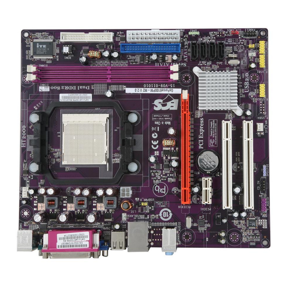
Motherboard Components Introducing the Motherboard... - Page 11 Table of Motherboard Components LABEL C O MPO NENTS Socket for AMD Phenom processor (socket AM2+)/AMD 1. CPU Socket Athlon 64 X2 Dual-Core/Athlon 64/Sempron processors 2. DIMM1~2 240-pin DDR2 SDRAM slots 3. FDD Floppy disk drive connector 4. PWR1 Standard 24-Pin AT X Power connector 5.
- Page 12 Memo Introducing the Motherboard...
-
Page 13: Installing The Motherboard
Chapter 2 Installing the Motherboard Safety Precautions • Follow these safety precautions when installing the motherboard • Wear a grounding strap attached to a grounded device to avoid dam- age from static electricity • Discharge static electricity by touching the metal case of a safely grounded object before working on the motherboard •... -
Page 14: Checking Jumper Settings
Do not over-tighten the screws as this can stress the motherboard. Checking Jumper Settings This section explains how to set jumpers for correct configuration of the motherboard. Setting Jumpers Use the motherboard jumpers to set system configuration options. Jumpers with more than one pin are numbered. -
Page 15: Checking Jumper Settings
Checking Jumper Settings The following illustration shows the location of the motherboard jumpers. Pin 1 is labeled. Jumper Settings Jumper Type Description Setting (default) 1-2: NORMAL 2-3: CLEAR CLR_CMOS 3-pin CLEAR CMOS Before clearing the CMOS, make sure to CLR_CMOS turn the system off. -
Page 16: Connecting Case Components
Connecting Case Components After you have installed the motherboard into a case, you can begin connecting the motherboard components. Refer to the following: Connect the CPU cooling fan cable to CPU_FAN. Connect the system cooling fan connector to SYS_FAN. Connect the standard power supply connector to PWR1. Connect the auxiliary case power supply connector to PWR2. -
Page 17: Atx 12V Power Connector
CPU_FAN: FAN Power Connector Signal Name Function System Ground Power +12V +12V Sense Sensor Control CPU FAN control Users please note that the fan connector supports the CPU cooling fan of 1.1A ~ 2.2A (26.4W max) at +12V. SYS_FAN: System Cooling FAN Power Connector Signal Name Function System Ground... -
Page 18: Front Panel Header
SPK1: Internal speaker header Signal Name Signal Front Panel Header The front panel header (PANEL1) provides a standard set of switch and LED headers commonly found on ATX or Micro ATX cases. Refer to the table below for informa- tion: Signal Function Signal... -
Page 19: Installing Hardware
Power Switch Supporting the power on/off function requires connecting pins 6 and 8 to a momen- tary-contact switch that is normally open. The switch should maintain contact for at least 50 ms to signal the power supply to switch on or off. The time requirement is due to internal de-bounce circuitry. -
Page 20: Cpu Installation Procedure
CPU Installation Procedure The following illustration shows CPU installation components. Unhook the locking lever of the CPU socket. Pull the locking lever away from the socket and raising it to the upright position. Match the pin1 corner marked as the beveled edge on the CPU with the pin1 corner on the socket. -
Page 21: Installing Memory Modules
Installing Memory Modules This motherboard accommodates two 240-pin unbuffered DIMMs and supports DDR2 800/667/533/400 DDR2 SDRAM. You must install at least one module in any of the two slots. Each module can be installed with 8 GB of memory; the total memory capacity is 16 GB. - Page 22 Table A: Unbuffered DIMM Support for Socket AM2 CPU Output Driver DRAM Timing Address Timing DIMM1 DIMM2 Compensation Speed Mode Control Register Control Register DDR2-400 002F_2F2Fh X011_1222h DDR2-400 002F_2F2Fh X011_1322h DDR2-533 002F_2F2Fh X011_1222h SRx16 SRx16 SRx16 SRx8 DDR2-533 002F_2F2Fh X011_1322h SRx8 SRx16 DDR2-533...
- Page 23 Table B: DDR2 (memory module) QVL (Qualified Vendor List) The following DDR2 memory modules have been tested and qualified for use with this motherboard. Type Size Vendor Module Name 256 MB Samsung M378T3354BZ 0-CCC K4T51163QB-ZCCC Samsung M378T3354BZ0-C CC K4T 51183QB-GCC C DDR2 400 512 MB TwinMos...
-
Page 24: Installing A Hard Disk Drive/Cd-Rom/Sata Hard Drive
Installing a Hard Disk Drive/CD-ROM/SATA Hard Drive This section describes how to install IDE devices such as a hard disk drive and a CD- ROM drive. About IDE Devices Your motherboard has one IDE interface. An IDE ribbon cable supporting two IDE devices is bundled with the motherboard. -
Page 25: Installing A Floppy Diskette Drive
Refer to the illustration below for proper installation: Attach either cable end to the connector on the motherboard. Attach the other cable end to the SATA hard drive. Attach the SATA power cable to the SATA hard drive and connect the other end to the power supply. -
Page 26: Installing Add-On Cards
Installing Add-on Cards The slots on this motherboard are designed to hold expansion cards and connect them to the system bus. Expansion slots are a means of adding or enhancing the motherboard’s features and capabilities. With these efficient facilities, you can increase the motherboard’s capabilities by adding hardware that performs tasks that are not part of the basic system. - Page 27 Follow these instructions to install an add-on card: Remove a blanking plate from the system case corresponding to the slot you are going to use. Install the edge connector of the add-on card into the expansion slot. Ensure that the edge connector is correctly seated in the slot. Secure the metal bracket of the card to the system case with a screw.
-
Page 28: Connecting Optional Devices
Connecting Optional Devices Refer to the following for information on connecting the motherboard’s optional devices: F_AUDIO: Front Panel Audio header This header allows the user to install auxiliary front-oriented microphone and line- out ports for easier access. Signal Name Signal Name Signal Name Function PORT 1L... - Page 29 IR1: Infrared header (optional) The motherboard supports an Infrared (IR1) data port. Infrared ports allow the wireless exchange of information between your computer and similarly equipped devices such as printers, laptops, Personal Digital Assistants (PDAs), and other computers. Signal Name Function Not Assigned Not assigned...
- Page 30 CD_IN: Analog Audio Input connector Signal Name Function CD_L CD In left channel Ground Ground CD_R CD In right channel Installing the Motherboard...
-
Page 31: Connecting I/O Devices
Connecting I/O Devices The backplane of the motherboard has the following I/O ports: PS2 Mouse Use the upper PS/2 port to connect a PS/2 pointing device. PS2 Keyboard Use the lower PS/2 port to connect a PS/2 keyboard. Parallel Port Use LPT to connect printers or other parallel communica- (LPT) tions devices. - Page 32 Memo Installing the Motherboard...
-
Page 33: Using Bios
Chapter 3 Using BIOS About the Setup Utility The computer uses the latest Phoenix-Award Workstation BIOS with support for Windows Plug and Play. The CMOS chip on the motherboard contains the ROM setup instructions for configuring the motherboard BIOS. The BIOS (Basic Input and Output System) Setup Utility displays the system ’ s configuration status and provides you with options to set system parameters. -
Page 34: Bios Navigation Keys
Press DEL to enter SETUP Pressing the delete key accesses the BIOS Setup Utility: Phoenix-Award WorkstationBIOS CMOS Setup Utility: Standard CMOS Features Load Fail-Safe Defaults Advanced BIOS Features Load optimized Defaults Advanced Chipset Features Set Supervisor Password Integrated Peripherals Set User Password Save &... -
Page 35: Updating The Bios
Updating the BIOS You can download and install updated BIOS for this motherboard from the manufacturer’s Web site. New BIOS provides support for new peripherals, improve- ments in performance, or fixes for known bugs. Install new BIOS as follows: If your motherboard has a BIOS protection jumper, change the setting to allow BIOS flashing. -
Page 36: Standard Cmos Feature
Standard CMOS Features This option displays basic information about your system. Phoenix-Award WorkstationBIOS CMOS Setup Utility Standard CMOS Features Date (mm:dd:yy) Mon, Jan.8 2007 Item Help Time (hh:mm:ss) 9 : 14 : 38 IDE Channel 0 Master [ None] Menu Level IDE Channel 0 Slave [ None] Change the day, month,... - Page 37 IDE HDD Auto-Detection Press <Enter> while this item is highlighted to prompt the Setup Utility to automati- cally detect and configure an IDE device on the IDE channel. If you are setting up a new hard disk drive that supports LBA mode, more than one line will appear in the parameter box.
-
Page 38: Advanced Bios Feature
Advanced BIOS Features This option defines advanced information about your system. Phoenix-Award WorkstationBIOS CMOS Setup Utility Advanced BIOS Features CPU Feature [Press Enter] Item Help Removable Device Priority [Press Enter] Hard Disk Boot Priority [Press Enter] Menu Level Network Boot Priority [Press Enter] CPU Internal Cache [Enabled]... - Page 39 Removable Device Priority (Press Enter) Scroll to this item and press <Enter> to view the following screen: Phoenix-Award WorkstationBIOS CMOS Setup Utility Removable Device Priority Item Help 1. Floppy Disks Menu Level Use < > or < > to select a device, then press <+>...
- Page 40 Network Boot Prioritiy (Press Enter) Scroll to this item and press <Enter> to view the following screen: Phoenix-Award WorkstationBIOS CMOS Setup Utility Network Boot Priority Item Help 1. Network 0: NVIDIA Boot Agent 227.0524 Menu Level Use < > or < >...
- Page 41 Gate A20 Option (Fast) This item defines how the sytem handles legacy software that was written for an earlier generation of processors. Leave this item at the default value. Typematic Rate Setting (Disabled) If this item is enabled, you can use the following two items to set the typematic rate and the typematic delay settings for your keyboard.
-
Page 42: Advanced Chipset Feature
Advanced Chipset Features These items define critical timing parameters of the motherboard. You should leave the items on this page at their default values unless you are very familiar with the technical specifications of your system hardware. If you change the values incor- rectly, you may introduce fatal errors or recurring instability into your system. - Page 43 DRAM Configuration n (Press Enter) Scroll to this item and press <Enter> to view the following screen: Phoenix-AwardBIOS CMOS Setup Utility DRAM Configuration Item Help Timing Mode [Auto] Memclock index value or Limi DDR2 400 Menu Level DQS Training Control [Skip DQS] DCTs Mode [Ganged]...
- Page 44 PCIE Spread Spectrum (Disabled) This item, when enabled, can significantly reduce the EMI (Electromagnetic Inter- ference) generated by the PCIE. SATA Spread Spectrum (Disabled) This item, when enabled, can significantly reduce the EMI (Electromagnetic Inter- ference) generated by the SATA. HT Spread Spectrum (Disabled) This item, when enabled, can significantly reduce the EMI (Electromagnetic Inter- ference) generated by the HT.
-
Page 45: Integrated Peripherals
Integrated Peripherals These options display items that define the operation of peripheral components on the system’s input/output ports. Phoenix-Award WorkstationBIOS CMOS Setup Utility Integrated Peripherals Item Help IDE Function Setup [Press Enter] RAID Config [Press Enter] Menu Level Onboard Device [Press Enter] Super IO Device [Press Enter]... - Page 46 Primary/Secondary Master/Slave UDMA (Auto) Each IDE channel supports a master device and a slave device. This motherboard supports UltraDMA technology, which provides faster access to IDE devices. If you install a device that supports UltraDMA, change the appropriate item on this list to Auto.
- Page 47 Onboard Device Setup (Press Enter) Scroll to this item and press <Enter> to view the following screen: Phoenix-Award WorkstationBIOS CMOS Setup Utility Onboard Device Item Help USB 2.0 controller [Enabled] USB Memory Type [SHADOW] USB Keyboard Support [Enabled] Menu Level USB Mouse Support [Enabled] USB Storage Support...
- Page 48 SuperIO Device (Press Enter) Scroll to this item and press <Enter> to view the following screen: Phoenix-Award WorkstationBIOS CMOS Setup Utility Super IO Device Item Help Onboard FDC Controller [Enabled] Onboard Serial Port 1 [3F8/IRQ4] Menu Level Onboard Parallel Port [378/IRQ7] Parallel Port Mode [SPP]...
-
Page 49: Power Management Setup
Power Management Setup This option lets you control system power management. The system has various power-saving modes including powering down the hard disk, turning off the video, suspending to RAM, and software power down that allows the system to be automatically resumed by certain events. -
Page 50: Pnp/Pci Configurations
Resume by WOM/RING (Disabled) An input signal on the serial Ring indicator (RI) line (in other words, and incoming call on the modem) awakens the system from a soft off state. Resume By USB (S3) (Disabled) This item allows users to enable or disable the USB device Walk-up from S3 mode. Resume By PS2 MS/KB(S3) (Disabled) These items enable or disable you to allow mouse or keyboard activity to awaken the system from power saving mode. -
Page 51: Pc Health Status
Init Display First (PCI Slot) This item allows you to choose the primary display card. Press <Esc> to return to the main menu setting page. PC Health Status On motherboards that support hardware monitoring, this item lets you monitor the parameters for critical voltages, temperatures and fan speeds. Phoenix-Award WorkstationBIOS CMOS Setup Utility PC Health Status Smart Fan Function... -
Page 52: Load Fail-Safe Defaults
CPU Smart Fan Function (Disabled) These items enable you to define the CPU/System temperatur by smartly adjusting the CPU/System fan. When it is set at certain temperature, the CPU/SYS Fan PWM value will change accordingly. Press <Esc> to return to the PC Health Status page. Shutdown Temperature (Disabled) Enables you to set the maximum temperature the system can reach before powering down. -
Page 53: Set Supervisor/User Password
Set Supervisor/User Password When this function is selected, the following message appears at the center of the screen to assist you in creating a password. ENTER PASSWORD Type the password, up to eight characters, and press <Enter>. The password typed now will clear any previously entered password from CMOS memory. You will be asked to confirm the password. - Page 54 Memo Using BIOS...
-
Page 55: Using The Motherboard Software
Chapter 4 Using the Motherboard Software About the Software CD-ROM The support software CD-ROM that is included in the motherboard package contains all the drivers and utility programs needed to properly run the bundled products. Below you can find a brief description of each software program, and the location for your motherboard version. -
Page 56: Running Setup
Setup Tab Setup Click the Setup button to run the software installation program. Select from the menu which software you want to install. Browse CD The Browse CD button is the standard Windows command that allows you to open Windows Explorer and show the contents of the support CD. - Page 57 Click Next. The following screen appears: Check the box next to the items you want to install. The default options are recom mended. Click Next run the Installation Wizard. An item installation screen appears: Follow the instructions on the screen to install the items. 1.
- Page 58 Method 1. Run Reboot Setup Windows Vista will block startup programs by default when installing drivers after the system restart. You must select taskbar icon Run Blocked Program and run Reboot Setup to install the next driver, until you finish all drivers installation. Method 2.
- Page 59 Select Classic View. Set User Account. Select Turn User Account Control on or off and press Continue. Using the Motherboard Software...
-
Page 60: Manual Installation
These software(s) are subject to change at anytime without prior notice. Please refer to the support CD for available software. Please go to ECS website to download AMD Cool’n’Quiet technology. This concludes chapter 4. Using the Motherboard Software... -
Page 61: Setting Up Nvidia Raid Configuration
Chapter 5 Setting Up NVIDIA RAID Configuration Setting Up a Non-Bootable RAID Array RAID arrays can be created/deleted using both MediaShield RAID BIOS and the MediaShield RAID Manager from Windows. This section only covers basic BIOS setup required for non-bootable array. See the section "Setting Up a Bootable RAID Array”... - Page 62 Use the arrow keys to select the RAID Config (see Figure 2.2), then press Enter. The RAID Config window appears. Figure 2.3 RAID Config Window From the RAID Config window, globally enable RAID, then enable the SATA ports with disks that you want to use for RAID. If RAID is enabled globally but not enabled on the individual SATA port, disks on that port can only be used for non-RAID applications.
- Page 63 Select the modules that you want to install. Make sure that the “NVIDIA IDE Driver” is selected. You must install the NVIDIA IDE driver in order to enable NVIDIA RAID. If you do not install the NVIDIA IDE driver, NVIDIA RAID will not be enabled.
-
Page 64: Setting Up A Bootable Raid Array
Setting Up a Bootable RAID Array This section explains how to configure a bootable NVIDIA RAID array. Setting Up the BIOS Start your computer, then press Delete to enter the BIOS setup. The BIOS CMOS Setup Utility screen appears. Figure 2.5 BIOS CMOS Setup Utility Main Screen Use the arrow keys to select Integrated Peripherals (see Figure 2.5), then press Enter. - Page 65 The RAID Config window appears. Figure 2.7 RAID Config Screen From the RAID Config window, globally enable RAID, then enable the SATA ports with disks that you want to use for RAID. If RAID is enabled globally but not enabled on the individual SATA port, disks on that port can only be used for non-RAID applications.
- Page 66 The NVIDIA RAID Utility—Define a New Array screen appears (Figure 2.8). Figure 2.8 NVIDIA RAID Utility By default, RAID Mode is set to Mirroring and Striping Block is set to Optimal. Using the Define a New Array Screen If necessary, press the tab key to move from field to field until the appropriate field is highlighted.
- Page 67 Figure 2.9 illustrates the Define a New Array screen after two disks have been assigned as RAID1 array disks. Figure 2.9 MediaShield Utility—Array Disks Assigned Completing the RAID BIOS Setup After assigning your RAID array disks, press F7. The Clear disk array prompt appears. Figure 2.10 Clear Disk Data Prompt NVIDIA RAID Configuration...
- Page 68 Press Y to clear the disk data. The Array List screen appears, where you can review the RAID arrays that you have set up. Figure 2.11 Array List Window Use the arrow keys to select the array that you want to set up, then press B to specify the array as bootable.
- Page 69 Installing the RAID Drivers Your system may come with a Windows install CD that already includes NVIDIA RAID drivers. If so, then this section is not relevant. If that is not the case (or you are trying to install a new version of Windows), then you will need an NVIDIA RAID driver F6 install floppy.
- Page 70 Select “NVIDIA RAID CLASS DRIVER (required)” and then press Enter. Press S again at the Specify Devices screen, then press Enter. Select “NVIDIA NForce Storage Controller (required)” and then press Enter. The following Windows Setup screen appears listing both drivers:. Figure 2.15 Windows Setup—NVIDIA drives listed Press Enter to continue with Windows XP Installation.
Need help?
Do you have a question about the GeForce 6100PM-M2 and is the answer not in the manual?
Questions and answers