Table of Contents
Advertisement
Advertisement
Table of Contents

Related Manuals for ECS 662/1066T-M2


Summary of Contents for ECS 662/1066T-M2
- Page 3 Preface Copyright This publication, including all photographs, illustrations and software, is protected under international copyright laws, with all rights reserved. Neither this manual, nor any of the material contained herein, may be reproduced without written consent of the author. Version 1.0 Disclaimer The information in this document is subject to change without notice.
- Page 4 Declaration of Conformity This device complies with part 15 of the FCC rules. Operation is subject to the following conditions: • This device may not cause harmful interference, and • This device must accept any interference received, including interference that may cause undesired operation Canadian Department of Communications This class B digital apparatus meets all requirements of the Canadian Interference-causing Equipment Regulations.
-
Page 5: Table Of Contents
T T T T T ABLE OF CONTENTS ABLE OF CONTENTS ABLE OF CONTENTS ABLE OF CONTENTS ABLE OF CONTENTS Preface Chapter 1 Introducing the Motherboard Introduction....................1 Feature......................2 Motherboard Components................4 Chapter 2 7 7 7 7 7 Installing the Motherboard Safety Precautions..................7 Choosing a Computer Case...............7 Installing the Motherboard in a Case............7... - Page 6 Integrated Peripherals..............32 Power Management Setup ............33 PCI/PnP Setup................34 PC Health Status................35 Frequency/Voltage Control ............36 Load Default Setting..............37 Supervisor/User Password............37 Save & Exit Setup ................38 Exit Without Saving..............38 Chapter 4 39 39 Using the Motherboard Software About the Software CD-ROM..............47 Auto-installing under Windows 2000/XP..........39 Running Setup................40 Manual Installation...................42 Utility Software Reference...............42...
-
Page 7: Introducing The Motherboard
Chapter 1 Introducing the Motherboard Introduction Thank you for choosing the 662/1066T-M2 motherboard. This motherboard is a high performance, enhanced function motherboard that supports LGA775 socket for latest Intel® Core 2 Duo/Pentium D/Pentium 4/Celeron D Processors. The motherboard incorporates the SiS662 Northbridge (NB) and SiS964 Southbridge (SB) chipsets. -
Page 8: Feature
Feature Processor This motherboard uses an LGA775 type of Intel® Core 2 Duo/Pentium D/Pentium 4/Celeron D that carries the following features: • Accommodates Intel® Core 2 Duo/Pentium D/Pentium 4/Celeron D pro- cessors • Supports a system bus (FSB) of 1066 (overclocking)/800/533 MHz •... - Page 9 Audio The motherboard may support either of the following Audio Chipset: • Compliant with AC’97 v2.3 CODEC • Supports 6-channel audio CODEC designed for PC multimedia systems • Provides three analog line-level stereo inputs with 5-bit volume control: Line-in,CD in •...
-
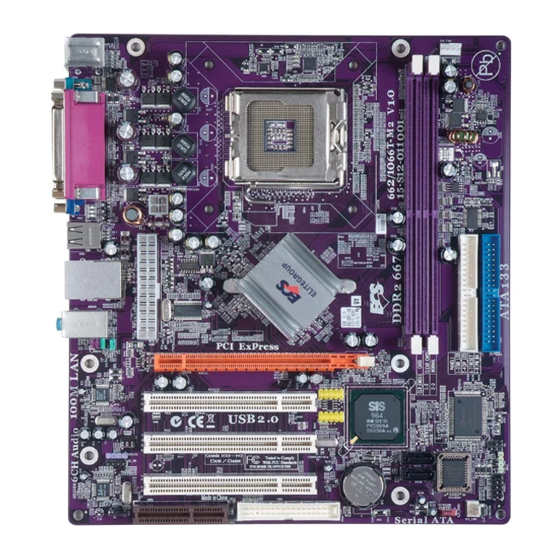
Page 10: Motherboard Components
Motherboard Components Introducing the Motherboard... - Page 11 Table of Motherboard Components LABEL COMPONENTS LGA775 socket for Intel Core 2 Duo/Pentium 1. CPU Socket D/Pentium 4/Celeron D CPUs 240-pin DDR2 SDRAM sockets 2. DDRII1~2 CPU Fan connector 3. CPU_FAN1 Primary IDE channel 4. IDE1 5. IDE2 Secondary IDE channel 6.
- Page 12 Memo Introducing the Motherboard...
-
Page 13: Installing The Motherboard
Chapter 2 Installing the Motherboard Safety Precautions • Follow these safety precautions when installing the motherboard • Wear a grounding strap attached to a grounded device to avoid damage from static electricity • Discharge static electricity by touching the metal case of a safely grounded object before working on the motherboard •... -
Page 14: Checking Jumper Settings
Do not over-tighten the screws as this can stress the motherboard. Checking Jumper Settings This section explains how to set jumpers for correct configuration of the motherboard. Setting Jumpers Use the motherboard jumpers to set system configuration options. Jumpers with more than one pin are numbered. -
Page 15: Checking Jumper Settings
Checking Jumper Settings The following illustration shows the location of the motherboard jumpers. Pin 1 is labeled. Jumper Settings Type Jumper Description Setting (default) 1-2: CLEAR CMOS 2-3: NORMAL CLR_CMOS1 3-pin CLEAR CMOS Before clearing the CMOS, CLR_CMOS1 make sure to turn off the sys- tem. -
Page 16: Connecting Case Components
Connecting Case Components After you have installed the motherboard into a case, you can begin con- necting the motherboard components. Refer to the following: Connect the CPU cooling fan cable to CPU_FAN1. Connect the case speaker cable to SPK1. Connect the system cooling fan connector to SYS_FAN1. Connect the case switches and indicator LEDs to the PANEL1. - Page 17 CPU_FAN1: Cooling Fan Connector Signal Name Function System Ground Power +12V +12V Sense Sensor FAN Control Signal Control Users please note that the fan connector supports the CPU cooling fan of 1.1A ~ 2.2A (26.4W max) at +12V. SYS_FAN1: FAN Power Connector Signal Name Function System Ground...
-
Page 18: Front Panel Connector
Front Panel Header The front panel header (PANEL1) provides a standard set of switch and LED headers commonly found on ATX or Micro ATX cases. Refer to the table below for information: Signal Function Signal Function HD_LED_P Hard disk LED (+) 2 FP PWR/SLP *MSG LED (+) HD_LED_N Hard disk LED (-) FP PWR/SLP *MSG LED (-) -
Page 19: Installing Hardware
Installing Hardware Installing the Processor Caution: When installing a CPU heatsink and cooling fan make sure that you DO NOT scratch the motherboard or any of the surface-mount resistors with the clip of the cooling fan. If the clip of the cooling fan scrapes across the motherboard, you may cause serious damage to the motherboard or its components. - Page 20 CPU Installation Procedure The following illustration shows CPU installation components. A. Read and follow the instructions shown on the sticker on the CPU cap. B. Unload the cap · Use thumb & forefinger to hold the lifting tab of the cap. ·...
-
Page 21: Installing Memory Modules
Installing Memory Modules This motherboard accommodates two memory modules. It can support two 240-pin unbuffered DIMM, DDR2 667/533/400. The total memory capacity is 2 GB. DDR2 SDRAM memory module table Memory module Memory Bus DDR2 400 200 MHz DDR2 533 266 MHz 333 MHz DDR2 667... - Page 22 Table A: DDR2 (memory module) QVL (Qualified Vendor List) The following DDR2 memory modules have been tested and qualified for use with this motherboard. Type Size Vendor Model Name SAMSUNG K4T56083QF-GCCC 256 MB DDR2 SAMSUNG K4T5163QB-ZCCC SAMSUNG K4T51083QB-GCCC 512 MB TwinMOS K4T51083QB-GCCC Elixir...
- Page 23 A-DATA Eipida E5108AE-6E-E A-DATA NT512T64U88A0BY-3C CORSAIR CM2X512-5400C4PRO CORSAIR VALUESELECT 32M8CEC CORSAIR 64M8CFEPS1000547 Eipida A-DATA E5108AE-6E-E GEIL GL2L64MO88BA18W Infinity 0547W64M8 512 MB Kingston D6408TE8EWL3 SAMSUNG K4T51083QC DDR2 SAMSUNG K4T56083QF-ZCE6 SyncMAX E5108AB-5C-E SyncMAX 64MX8 D2-F SLX264M8-T6E Transcend K4T51083QC TwinMOS TMM6208G8M30B Apacer E5108AE-6E-E Infineon HYB18T512800AF3S 1 GB...
-
Page 24: Installing A Hard Disk Drive/Cd-Rom/Sata Hard Drive
Installing a Hard Dish Drive/CD-ROM/SATA Hard Drive This section describes how to install IDE devices such as a hard disk drive and a CD-ROM drive. About IDE Devices Your motherboard has a primary and secondary IDE channel interface (IDE1 and IDE2). An IDE ribbon cable supporting two IDE devices is bundled with the motherboard. -
Page 25: Installing A Floppy Diskette Drive
Installing Serial ATA Hard Drives To install the Serial ATA (SATA) hard drives, use the SATA cable that supports the Serial ATA protocol. This SATA cable comes with an SATA power cable. You can connect either end of the SATA cable to the SATA hard drive or the connector on the motherboard. SATA cable SATA power cable (optional) -
Page 26: Installing Add-On Cards
Installing Add-on Cards The slots on this motherboard are designed to hold expansion cards and connect them to the system bus. Expansion slots are a means of adding or enhancing the motherboard’s features and capabilities. With these efficient facilities, you can increase the motherboard’s capabili- ties by adding hardware that performs tasks that are not part of the basic system. -
Page 27: Connecting Optional Devices
Follow these instructions to install an add-on card: Remove a blanking plate from the system case corresponding to the slot you are going to use. Install the edge connector of the add-on card into the expansion slot. Ensure that the edge connector is correctly seated in the slot. Secure the metal bracket of the card to the system case with a screw. - Page 28 F_AUDIO1: Front Panel Audio header This header allows the user to install auxiliary front-oriented microphone and line-out ports for easier access. Signal Name Signal Name Function AUD_MIC Front Panel Microphone input signal AUD_GND Ground used by Analog Audio Circuits AUD_MIC_BIAS Microphone Power AUD_VCC Filtered +5V used by Analog Audio Circuits AUD_F_R...
- Page 29 F_USB1/2: Front Panel USB headers The motherboard has four USB ports installed on the rear edge I/O port array. Additionally, some computer cases have USB ports at the front of the case. If you have this kind of case, use auxiliary USB connector to connect the front-mounted ports to the motherboard. Signal Name Function USBPWR...
-
Page 30: Connecting I/O Devices
Connecting I/O Devices The backplane of the motherboard has the following I/O ports: PS2 Mouse Use the upper PS/2 port to connect a PS/2 pointing device. PS2 Keyboard Use the lower PS/2 port to connect a PS/2 keyboard. Parallel Port (LPT1) Use LPT1 to connect printers or other parallel communications devices. -
Page 31: Using Bios
Chapter 3 Using BIOS About the Setup Utility The computer uses the latest American Megatrends BIOS with support for Windows Plug and Play. The CMOS chip on the motherboard contains the ROM setup instructions for configuring the motherboard BIOS. The BIOS (Basic Input and Output System) Setup Utility displays the system’s configura- tion status and provides you with options to set system parameters. - Page 32 Phoenix-AwardBIOS CMOS Setup Utility: Press DEL to enter SETUP Pressing the delete key accesses the BIOS Setup Utility: CMOS Setup Utility – Copyright (C) 1985-2005, American Megatrends, Inc. Standard CMOS Setup Frequency/Voltage Control Advanced Setup Load Default Settings Advanced Chipset Setup Supervisor Password Integrated Peripherals User Password...
-
Page 33: Updating The Bios
Updating the BIOS You can download and install updated BIOS for this motherboard from the manufacturer’s Web site. New BIOS provides support for new peripherals, improvements in performance, or fixes for known bugs. Install new BIOS as follows: If your motherboard has a BIOS protection jumper, change the setting to allow BIOS flashing. -
Page 34: Standard Cmos Setup
Standard CMOS Setup This option displays basic information about your system. CMOS Setup Utility – Copyright (C) 1985-2005, American Megatrends, Inc. Standard CMOS Setup Item Help Date Tuet 12/05/2006 Time 17:26:11 User [Enter], [TAB] Primary IDE Master Not Detected or [SHIFT-TAB] to Primary IDE Slave Not Detected select a field. -
Page 35: Advanced Setup
Advanced Setup This option defines advanced information about your system. CMOS Setup Utility – Copyright (C) 1985-2005, American Megatrends, Inc. Advanced Setup Item Help Thermal Management Enabled TM Status Limit CPUID MaxVal Disabled For the processor its CPUID Enhanced Halt (C1E) Enabled belows 0F41h. - Page 36 APIC Mode (Enabled) This item allows you to enable or disable the APIC (Advanced Programmable Interrupt Controller) mode. APIC provides symmetric multi-processing (SMP) for systems, allowing support for up to 60 processors. 1st/2nd/3rd Boot Device (Hard Drive/Pioneer DVD-ROM ATA/1st FLOPPY DRIVE) Use these items to determine the device order the computer uses to look for an operating system to load at start-up time.
-
Page 37: Advanced Chipset Setup
Advanced Chipset Setup These items define critical timing parameters of the motherboard. You should leave the items on this page at their default values unless you are very familiar with the technical specifications of your system hardware. If you change the values incorrectly, you may introduce fatal errors or recurring instability into your system. -
Page 38: Integrated Peripherals
Integrated Peripherals These options display items that define the operation of peripheral components on the system’s input/output ports. CMOS Setup Utility – Copyright (C) 1985-2005, American Megatrends, Inc. Integrated Peripherals Item Help Both Onboard IDE Controller Onboard PCI S-ATA Controller Enabled DISABLED: disables the USB Controller... -
Page 39: Power Management Setup
Parallel Port Address (378) Use this item to enable or disable the onboard Parallel port, and to assign a port address. Parallel Port Mode (ECP) Use this item to set the parallel port mode. You can select Normal (Standard Parallel Port), ECP (Extended Capabilities Port), EPP (Enhanced Parallel Port), or EPP &... -
Page 40: Pci/Pnp Setup
Resume on LAN (Disabled) This item allows users to enable or disable LAN activity to wake up the system from power saving mode. Wake-Up by PME (Enabled) This item allows users to enable or disable PCI activity to wake up the system form a power saving mode. -
Page 41: Pc Health Status
PC Health Status On motherboards that support hardware monitoring, this item lets you monitor the parameters for critical voltages, temperatures and fan speeds. CMOS Setup Utility – Copyright (C) 1985-2005, American Megatrends, Inc. PC Health Status Item Help Hardware Health Event Monitoring Smart Fan Function Press Enter Shutdown Temperature... -
Page 42: Frequency/Voltage Control
Frequency/Voltage Control This item enables you to set the clock speed and system bus for your system. The clock speed and system bus are determined by the kind of processor you have installed in your system. CMOS Setup Utility – Copyright (C) 1985-2005, American Megatrends, Inc. Frequency/Voltage Control Item Help Manufacturer: Intel... -
Page 43: Load Default Setting
Load Default Setting This option opens a dialog box to ask if you are sure to install optimized defaults or not. You select [OK], and then press <Enter>, the Setup Utility loads all default values; or select [Cancel], and then press <Enter>, the Setup Utility does not load default values. -
Page 44: Save & Exit Setup
Save & Exit Setup Highlight this item and press <Enter> to save the changes that you have made in the Setup Utility configuration. When the Save & Exit dialog box appears, select [OK] to save and exit, or select [Cancel] to return to the main menu. Exit Without Saving Highlight this item and press <Enter>... -
Page 45: Using The Motherboard Software
Chapter 4 Using the Motherboard Software About the Software CD-ROM The support software CD-ROM that is included in the motherboard package contains all the drivers and utility programs needed to properly run the bundled products. Below you can find a brief description of each software program, and the location for your motherboard version. -
Page 46: Running Setup
Setup Tab Setup Click the Setup button to run the software installation program. Select from the menu which software you want to install. Browse CD The Browse CD button is the standard Windows command that allows you to open Windows Explorer and show the contents of the support Before installing the software from Windows Explorer, look for a file named README.TXT, INSTALL.TXT or something similar. - Page 47 Click Next. The following screen appears: Check the box next to the items you want to install. The default options are recommended. Click Next run the Installation Wizard. An item installation screen appears: Follow the instructions on the screen to install the items. Drivers and software are automatically installed in sequence.
-
Page 48: Manual Installation
Manual Installation Insert the CD in the CD-ROM drive and locate the PATH.DOC file in the root directory. This file contains the information needed to locate the drivers for your motherboard. Look for the chipset and motherboard model; then browse to the directory and path to begin installing the drivers. -
Page 49: Sis964 Sata Raid Setup Guide
Chapter 5 SiS 964 SATA RAID Setup Guide Introduction for SiS964 SATA RAID Function The 964 S-ATA controller only support two serial ATA on two independent ports. The Serial ATA RAID is designed to provide a cost-effective, high performance RAID solution that adds performance and/or reliability to PC desktops and/or servers using Serial ATA/150 hard disks. -
Page 50: Installing Software Drivers
JBOD: (Just a Bunch of Drives). Also known as “Spanning”. Two or more hard drives are required. Several hard disk types configured as a single hard disk. The hard drives are simply hooked up in series. This expands the capacity of your drive and results in a useable total capacity. -
Page 51: Bios Utility Operation
Confirming Windows 98/Me Driver Installation From Windows 98/Me, open the Control Panel from “My Computer” followed by the System icon. Choose the “Device Manager” tab. Click the “+” in front of “IDE ATA/ATAPI Controllers” hardware type. The driver “SiS 180 IDE Dual Channel” and “SiS 180 IDE/RAID Controller” should appear. - Page 52 Create RAID • SIS 964 controller support RAID 0, RAID 1 and JBOD. Creating a RAID 0 (Stripe) Array for Performance • SIS 180 enables users to create striped arrays with 2, 3, or 4 drives. • SIS 964 only supports 2 SATA drivers to create a stripe array. To create an array for best performance, follow these steps: Press <A>...
- Page 53 Use < > < > to select disk, and press <Enter> to select disk, <Q> to exit. ↑ ↓ When you press <Enter> on the disk you wanted, the RAID Type will be changed from Single to RAID 0. An the disk you select first will be the SOURCE disk.
- Page 54 Press <Q> again to exit this BIOS utility and the red message frame will show. Press <Y> and <Enter> to save changes. Once the array has been created, you will need to FDISK and format the array as if it were a new single hard drive. Creating a RAID 1 (Mirror) Array SIS 964/180 enables users to create Mirror arrays with 2 drives only.
- Page 55 Use < > < > to select disk, and press <Enter> to select disk, <Q> to exit. ↑ ↓ When you press <Enter> on the disk you wanted, the RAID Type will be changed from Single to RAID 1. The same as RAID 0, the disk you select first will be the SOURCE disk.
- Page 56 Press <Q> again to exit this BIOS utility and the red message frame will show as the same as the creation of the RAID 0 array. Press <Y> and <Enter> to save changes. Once the array has been created, you will need to FDISK and format the array as if it were a new single hard drive.
- Page 57 Press <Q> again to exit this BIOS utility and the red message frame will show as the same age as the creation of the RAID 0 array. Press <Y> and <Enter> to save changes. Once the array has been created, you will need to FDISK and format the array as if it were a new single hard drive.
Need help?
Do you have a question about the 662/1066T-M2 and is the answer not in the manual?
Questions and answers