Table of Contents
Advertisement
Quick Links
Copyright
This publication, including all photographs, illustrations and software, is protected un-
der international copyright laws, with all rights reserved. Neither this manual, nor any
of the material contained herein, may be reproduced without written consent of the au-
thor.
Version 1.0
Disclaimer
The information in this document is subject to change without notice. The manufac-
turer makes no representations or warranties with respect to the contents hereof and
specifically disclaim any implied warranties of merchantability or fitness for any p
ticular purpose. The manufacturer reserves the right to revise this publication and to
make changes from time to time in the content hereof without obligation of the ma
facturer to notify any person of such revision or changes.
Trademark Recognition
Microsoft, MS-DOS and Windows are registered trademarks of Microsoft Corp.
MMX, Pentium, Pentium-II, Pentium-III, Celeron are registered trademarks of Intel
Corporation.
Other product names used in this manual are the properties of their respective owners
and are acknowledged.
Federal Communications Commission (FCC)
This equipment has been tested and found to comply with the limits for a Class B digi-
tal device, pursuant to Part 15 of the FCC Rules. These limits are designed to provide
reasonable protection against harmful interference in a residential installation. This
equipment generates, uses, and can radiate radio frequency energy and, if not in-
stalled and used in accordance with the instructions, may cause harmful interference
to radio communications. However, there is no guarantee that interference will not oc-
cur in a particular installation. If this equipment does cause harmful interference to
radio or television reception, which can be determined by turning the equipment off
and on, the user is encouraged to try to correct the interference by one or more of the
following measures:
−
Reorient or relocate the receiving antenna.
−
Increase the separation between the equipment and the receiver.
−
Connect the equipment onto an outlet on a circuit different from that to which
the receiver is connected.
−
Consult the dealer or an experienced radio/TV technician for help.
Shielded interconnect cables and a shielded AC power cable must be employed with
this equipment to ensure compliance with the pertinent RF emission limits governing
this device. Changes or modifications not expressly approved by the system's manu-
facturer could void the user's authority to operate the equipment.
Preface
ar-
nu-
Advertisement
Table of Contents

Related Manuals for ECS 651-M


Summary of Contents for ECS 651-M
- Page 1 Preface Copyright This publication, including all photographs, illustrations and software, is protected un- der international copyright laws, with all rights reserved. Neither this manual, nor any of the material contained herein, may be reproduced without written consent of the au- thor.
- Page 2 Declaration of Conformity This device complies with part 15 of the FCC rules. Operation is subject to the follow- ing conditions: − This device may not cause harmful interference, and − This device must accept any interference received, including interference that may cause undesired operation.
- Page 3 Features Translations Caractéristiques Processeur La carte mère utilise un Socket micro PGA 478 broches pré- sentant les caractéristiques suivantes : • Supporte un bus frontal (FSB) de 400/533 MHz • Accepte des processeurs Pentium 4 à 1.5G/1.6G/1.7G… 3.06G et plus Chipset Les chipsets SiS650GX B0 Northbridge et SiS962L South- bridge sont basés sur une architecture novatrice et...
- Page 4 have small buffers even at high data rates. The USB 1.1 connectors and other full speed cables can support the higher speed of USB 2.0 without any changes. The chipset has the following advanced USB features: • Compliant with Enhanced Host Controller Interface (EHCI) Specification Revision 0.95 and Universal Host Controller Interface (UHCI) Specification Revision 1.1 •...
- Page 5 • Gestion d’alimentation • Alarmes de réveil • Paramètres de CPU • Synchronisation de CPU et de mémoire Le microprogramme peut aussi être utilisé pour définir les paramètres pour les vitesses d’horloges de différents proces- seurs. Certaines spécifications matérielles et éléments de logiciels peuvent être modifiés sans avertissement.
- Page 6 Features Prozessor Das Motherboard verwendet einen Mikro-PGA 478-Pin Sockel mit den folgenden Eigenschaften: • Unterstützt 400/533 MHz Frontsidebus (FSB) • Nimmt Pentium 4 Prozessoren mit 1.5G/1.6G/1.7G… 3.05G und darüber auf Chipsatz Die Chipsätze SiS650GX B0 Northbridge und SiS962L Southbridge basieren auf einer innovativen und skalierbaren Architektur mit bewiesener Zuverlässigkeit und Leistung.
- Page 7 Controllern für Signalübertragung bei voller und niedriger Geschwindigkeit sowie einem EHCI-Host • Controllerkern für Hochgeschwindigkeits- Signalübertragung • Unterstützt PCI-Bus Power Management Interface Spezifikation Ausgabe 1.1 • Legacy-Unterstützung für alle Downstream-Ports Grafik Das Motherboard enthält einen 4x AGP-Steckplatz mit der vierfachen Bandbreite der ursprünglichen AGP-Spezifikation. AGP-Technologie bietet eine direkte Verbindung zwischen dem Grafiksubsystem und dem Speicher, so dass die Grafik nicht mit anderen Geräten auf dem PCI-Bus um Prozessorzeit wetteifern...
- Page 8 • CPU-Parameter • CPU- und Speichertiming Mit der Firmware können auch die Parameter für verschiedene Prozessortaktgeschwindigkeiten eingestellt werden. Bestimmte Hardwarespezifikationen und Teile der Softwareausstattung können ohne weitere Ankündigung abgeändert werden. viii...
- Page 9 Caratteristiche Processor La scheda madre usa un socket micro PGA 478-pin con le seguenti caratteristiche: • Supporto per il bus di sistema frontside (FSB) 400/533 • Alloggia processori Pentium 4 a 1,5G/1,6G/1,7G… 3,08G e superiore Chipset I chipset SiS650GX B0 Northbridge e SiS962L Southbridge sono basati su un'architettura innovativa e scalabile di provata affidabilità...
- Page 10 per la trasmissione segnali ad alta velocità. • Supporto per interfaccia risparmio energia bus PCI specifiche release 1.1 • Supporto per tutte le porte downstream precedenti Grafica La scheda madre include uno slot AGP che fornisce fino a quattro volte l’ampiezza di banda delle caratteristiche tecniche dell’AGP originale.
- Page 11 Alcune specifiche hardware ed elementi software sono soggetti a variazioni senza preavviso.
- Page 12 Características Procesador La placa principal usa un micro receptáculo PGA de 478 pines que tiene las siguientes características: • Soporta un bus frontal de 400/533 MHz (FSB)” • Acomoda procesadores Pentium 4 en 1.5G/1.6G/1.7G… 3.06G y por encima de estos Chipset Los chipsets Northbridge SiS650GX B0 y Southbridge SiS962L están basados en una arquitectura innovadora y...
- Page 13 nes UHCI para la señalización de velocidad completa/baja y un Anfitrión EHCI • Soporta PCI-BUS Interfaz de Administración de Energía Especificación edición 1.1 • Soporte de legado para todos los puertos frontales infe- riores Gráficas La placa principal incluye una ranura AGP que proporciona cinco veces el ancho de banda de la especificación AGP origi- nal.
- Page 14 • Cronometraje de CPU y de memoria También se puede usar el firmware para configurar los pará- metros para diferentes velocidades de reloj del procesador. Algunas especificaciones de hardware e ítems de software son sujetos a cambio sin previo aviso.
- Page 15 製品特徴 プロセッサ 本メインボードに搭載されているマイクロPGA478ピンソケッ トは、次の特徴があります。 • 400/533MHzのシステムバス(FSB)をサポートします • 1.5G/1.6G/1.7G…2.5G以上でPentium 4プロセッサに対 応しています チップセット 搭載した SiS650GX B0 NorthbridgeおよびSiS962L South bridgeチップセットは最新且つ拡張性あるアーキテクチャを 採用し、高い安定性およびパフォーマンスを兼ね備えたもの です。 • 533/400MHzのデータ通信速度でIntel Pentium 4シリーズ CPUに対応 • 12の優れた処理機能に対応 • DDR333/DDR266/200 SDRAM対応 • AGP v2.0対応 • 4MB~256MBのグラフィック ウィンドウサイズ対応 • 66MHz x 4モードで533MB/秒バンド幅を実現 • 高品質3Dエンジン内蔵...
- Page 16 • PCIマルチ機能デバイスは2つのフルスピード/ロースピー ド伝送用UHCIホストコントローラおよび1つのEHCIホスト で構成されています • PCIバス電源管理インターフェース1.1仕様に適合 • すべてのダウンストリームフェースポートをサポート グラフィック 搭載されているAGP スロットは、オリジナルのAGP仕様の4倍 にもなる帯域幅をサポートします。AGP技術はグラフィクサブ システムをプロセッサに直接アクセスさせることにより、PCIバ スにある他のデバイスと競合せずに、プロセッサによる高速な グラフィク処理を実現するものです。 AC’ 97 AC’ 97 オーディオコーデックはAC’ 97 2.3 仕様に適合し オーディオコーデ たもので、PC2001要求を満たし、S/PDIF Outに対応して ック います。また、内蔵バッファ及び内部PLLを搭載しています。 背面アナログスイッチ (共有)、ライン入力ジャック(共有)、 中央/ベース (共有)、6チャンネルオーディおへのMIC出力 ジャックなどの機能を含みます。 メモ: オプショナル4チャンネルオーディオコントローラ オンボードLAN機 VT6103L はカテゴリ5案シールド、Type 1 シールド、光ファ 能...
- Page 17 • CPUパラメータ • CPUおよびメモリのタイミング その他に、各種プロセッサクロック速度のパラメータを設定 することができます。 一部のハードウェア仕様及びソフトウェアアイテムは予告なく変更されるこ とがあります。 xvii...
- Page 18 기능 프로세서 본 메인보드는 micro PGA 478 핀 소켓을 사용하며 다음과 같은 특징을 지닌다: • 400/533 MHz frontside bus (FSB) 지원 • 1.5G/1.6G/1.7G… 3.06G 이상의 Pentium 4 프로세서 사용 3.06G 칩셋 SiS650GX B0 Northbridge 과 SiS962L Southbridge 칩셋은 혁신적이고 범위성을 지닌 아키텍쳐를 바탕으로 인정된신뢰 성과...
- Page 19 • PCI-버스 전원 관리 인터페이스 1.1 사양 지원 • 모든 다운스트림 페이싱 포트를 지원하는 Legacy 그래픽 본 메인보드에는 기존 AGP 사양보다 4 배의 대역폭을 제공하는 4x AGP 슬롯이 포함되어 있다. AGP 기술은 그래픽 서브 시스템과 프로세서를 직접 연결함으로써 그래픽 프로세서 시간을 PCI 버스에 있는 다른 장치와 다툴 필요가 없다.
- Page 20 본 메인보드는 Award BIOS 를 사용하여 사용자는 다음과 BIOS 펌웨어 같은 시스템 기능을 구성할 수 있다: • 전원 관리 • Wake-up 알람 • CPU 파라미터 • CPU 및 메모리 타이밍 펌웨어는 다른 프로세서의 클럭 속도를 설정하는 데도 사용될 수 있다. 하드웨어...
- Page 21 性能 中央處理器 本主機板採用了具有下列功能之微PGA 478針插槽: • 支援400/533MHz的前側匯流排(FSB) • 支援1.5G/1.6G/1.7G/3.06G及以上之 Pentium 4 處理器 晶片組 SiS650GX B0 北橋及 SiS962L 南橋晶片組,採用了獨創且具有 擴充功能的架構,能夠發揮最佳的穩定性及功能。 • 支援Intel Pentium 4系列CPU,位元傳輸速率高達533/ 400MHz • 支援12個未結束傳送 (outstanding transactions) • 支援DDR333/DDR266/200 SDRAM • 相容於AGP v2.0 • 支援4到256 Mbytes之圖形視窗大小 • 藉由66MHz x4模式,提供效能高達每秒533MB之頻寬 • 內建高品質3D立體圖像處理引擎...
- Page 22 時,本解碼/編碼器也具有內建緩衝器和內裝PLL。藉由對後聲 道輸出 (共用) 端子、外部音源輸入 (共用) 端子、中低音 (共用) 端子、及麥克風端子的切換功能,提供6聲道的音效輸出。 附註: 可選購4聲道音響控制器。 機載LAN功能 VT6103L係為乙太10BASE-T 和 100BASE-TX之實體層元件, 使用 (選購) Category 5(速率100 Mbps) 無遮蔽式雙絞線, Type 1屏蔽電纜以及 光纖電纜。 • 支援雙速 – 100/10 Mbps 傳輸速率 • 支援半或全雙工運作模式 • 提供乙太網路的MII介面 • 適用於所有可用之IEEE 802.3, 10BaseT和100Base-Tx雙絞線, 等之標準 擴充選項 本主機板具有下列的擴充選擇: •...
- Page 23 特性 处理器 主板使用一个 micro PGA 478-pin 插座,此插座具有以下特 点: • 支持 400/533 MHz 前端总线 (FSB) • 支持 1.5G/1.6G/1.7G/3.06G 或更高速度的 Pentium 4 处理器 芯片组 SiS650GX B0 北桥和SiS962L 南桥芯片组是基于一种新型的、 可扩展的架构,能提供已经证明的可靠性和高性能。 • 支持 Intel Pentium 4 系列 CPU,数据传输速率可达 533MHz • 支持 12 个未完成的事务处理 • 支持...
- Page 24 AC’ 97 Audio AC’ 97 音频编解码器符合 AC 97 2.3 PC2001 规格,支持 Codec S/PDIF Out。它还带有一个内置的缓冲器和一个内部 PLL。 功能包括支持后端模拟开关(共享)、线入插孔(共享)、中 置/低音(共享)和 MIC 插孔以输出 6 声道音频。 说明:可选 4-通道音频控制器 Onboard LAN VT6103L 是一种物理层设备,可用于使用 5 类非屏蔽线、1 (可选) 类屏蔽线和光缆的以太网 10BASE-T 和 100BASE-TX。 • 双速 -100/10 Mbps • 半双工和全双工 •...
-
Page 25: Table Of Contents
Preface Features Translations CHAPTER 1 Introducing the Motherboard Introduction ....................1 Features .....................2 Choosing a Computer Case ...............4 Motherboard Components ................5 CHAPTER 2 Installing the Motherboard Safety Precautions..................7 Quick Guide ....................7 Installing the Motherboard in a Case ............8 Checking Jumper Settings ................8 Setting Jumpers .................... - Page 26 PNP/PCI Configurations................41 PC Health Status.................... 42 Frequency/Voltage Control................43 Load Fail-Safe Defaults Option..............44 Load Optimized Defaults Option..............44 Set Password....................44 Save & Exit Setup Option ................45 Exit Without Saving ..................45 CHAPTER 4 Using the Motherboard Software About the Software CD-ROM ..............46 Auto-installing under Windows 98/ME/2000/XP ........46 Running Setup ....................
-
Page 27: Introducing The Motherboard
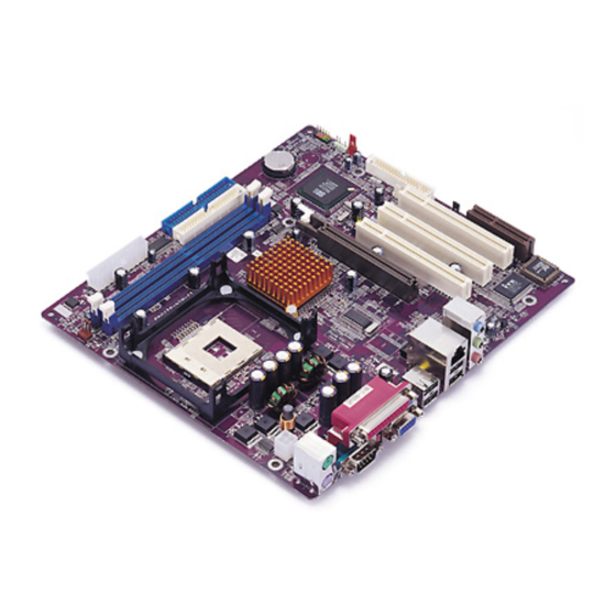
(CNR) slot provide ex- pandability for add-on peripheral cards. Featuring good stability and performance, and the advanced SiS chipset, the 651-M is an excellent Pentium 4 DDR motherboard for the budget-conscious consumer. It is the ideal solution for any home or workstation PC. -
Page 28: Features
Processor The motherboard uses a micro PGA 478-pin socket that has the following features: • Supports 400/533 MHz frontside bus (FSB) • Accommodates Pentium 4 processors at 1.5G/1.6G/1.7G …3.06G and above Chipset The SiS650GX B0 Northbridge and SiS962L Southbridge chipsets are based on an innovative and scalable architecture with proven reliability and performance. - Page 29 • PCI multi-function device consists of two UHCI Host Control- lers for full/low-speed signaling and one EHCI Host Controller core for high-speed signaling • Supports PCI-Bus Power Management Interface Specifi- cation release 1.1 • Legacy support for all downstream facing ports AC’...
-
Page 30: Choosing A Computer Case
There are many types of computer cases on the market. The motherboard complies with the specifications for the Micro ATX system case. Some fea- tures on the motherboard are implemented by cabling connectors on the motherboard to indicators and switches on the system case. Ensure that your case supports all the features required. - Page 32 Table of Motherboard Components Label Component AGP1 Accelerated Graphics Port ATX1 Auxiliary power connector for Pentium 4 CPUs ATX2 Standard 20-pin ATX power connector AUDIO1 Front audio connector BAT1 Three volt realtime clock battery CASFAN1 Case fan connector 1 CDIN1 Primary CD-in connector CNR1 Communications Networking Riser slot...
-
Page 33: Installing The Motherboard
Installing the Motherboard Follow these safety precautions when installing the motherboard: • Wear a grounding strap attached to a grounded device to avoid damage from static electricity. • Discharge static electricity by touching the metal case of a safely grounded object before working on the motherboard. •... -
Page 34: Installing The Motherboard In A Case
Refer to the following illustration and instructions for installing the mother- board in a case: This illustration shows an ex- 2. Secure the mainboard with ample of a motherboard being screws where appropriate. installed in a tower-type case: Note: Do not overtighten the screws as this can stress the moth- erboard. -
Page 35: Checking Jumper Settings
Checking Jumper Settings The following illustration shows the location of the motherboard jumpers. Pin 1 is labeled. Jumper Settings Jumper Type Description Setting (default) 3-pin Clear CMOS 1-2: Normal 2-3: Clear Before clearing the CMOS, make sure to turn the system off. 3-pin BIOS protect 1-2: Write Enabled... -
Page 36: Connecting Case Components
After you have installed the motherboard into a case, you can begin connect- ing the motherboard components. Refer to the following: Connect the Pentium 4 processor auxiliary case power supply connector to ATX1. Connect the standard power supply connec- tor to ATX2. Connect the CPU cooling fan cable to CPUFAN1. - Page 37 CPUFAN1/CASFAN1/PWRFAN1 (optional): FAN Power Connectors Signal Name Function System Ground +12V Power +12V Sense Sensor SPEAKER1: Internal speaker Signal Name Signal Ground SJ1: Single color LED header (optional) Signal Name Function ACPI LED MSG LED (-) green ACPI LED MSG LED (-) green SB5V Power LED (+) ACPI LED function:...
-
Page 38: Front Panel Connector
Front Panel Connector The front panel connector (PANEL1) provides a standard set of switch and LED connectors commonly found on ATX or micro-ATX cases. Refer to the table below for information: Signal Function Signal Function Hard disk LED MSG LED [dual color HD_LED_P FP PWR/SLP (positive) -
Page 39: Installing Hardware
Installing the Processor Caution: When installing a CPU heatsink and cooling fan make sure that you DO NOT scratch the motherboard or any of the surface-mount resis- tors with the clip of the cooling fan. If the clip of the cooling fan scrapes across the motherboard, you may cause serious damage to the mother- board or its components. - Page 40 CPU Installation Procedure The following illustration shows CPU installation components: Note: The pin-1 corner is marked with an arrow Follow these instructions to install the Retention Module and CPU: 1. Press the lever down. 2. Apply thermal grease on top of the CPU.
-
Page 41: Installing Memory Modules
3. Put the CPU Fan down on the retention module and snap the four retention legs of the cooling fan into place. 4. Flip the levers over to lock the heat sink in place. 5. Connect the CPU Cooling Fan power cable to the CPUFAN1 connector. -
Page 42: Installing A Hard Disk Drive/Cd-Rom
to insert any other type of DDR SDRAM into the slots. Push the latches on each side of the DIMM slot down. Align the memory module with the slot. The DIMM slots are keyed with notches and the DIMMs are keyed with cutouts so that they can only be installed correctly. - Page 43 IDE1: Primary IDE Connector The first hard drive should always be connected to IDE1. IDE2: Secondary IDE The second drive on this controller must be set to slave mode. The configura- tion is the same as IDE1. IDE devices have jumpers or switches that are used to set the IDE device as MASTER or SLAVE.
-
Page 44: Installing A Floppy Diskette Drive
Installing a Floppy Diskette Drive The mainboard has a floppy diskette drive (FDD) interface and ships with a diskette drive ribbon cable that supports one or two floppy diskette drives. You can install a 5.25-inch drive and a 3.5-inch drive with various capacities. The floppy diskette drive cable has one type of connector for a 5.25-inch drive and another type of connector for a 3.5-inch drive. -
Page 45: Installing Add-On Cards
Installing Add-on Cards The slots in this motherboard are designed to hold expansion cards and con- nect them to the system bus. Expansion slots are a means of adding or enhancing the motherboard’s features and capabilities. With these efficient facilities, you can increase the motherboard’s capabilities by adding hardware which performs tasks that are not part of the basic system. - Page 46 Follow these instructions to install an add-on card: Remove a blanking plate from the system case corresponding to the slot you are going to use. Install the edge connector of the add-on card into the expansion slot. Ensure that the edge con- nector is correctly seated in the slot.
-
Page 47: Connecting Optional Devices
Connecting Optional Devices Refer to the following for information on connecting the motherboard’s op- tional devices: AUDIO1: Front Panel Audio header This header allows the user to install auxiliary front-oriented microphone and line-out ports for easier access. Signal Name Function AUD_MIC Front Panel Microphone input signal AUD_GND... - Page 48 USB3: Front panel USB ports The motherboard has two USB ports installed on the rear edge I/O port array. Additionally, some computer cases have USB ports at the front of the case. If you have this kind of case, use auxiliary USB connector USB3 to connect the front-mounted ports to the motherboard.
-
Page 49: Connecting I/O Devices
SPDIF1: SPDIF out header (optional) This is an optional header that provides an S/PDIF (Sony/Philips Digital Inter- face) output to digital multimedia device through optical fiber or coaxial connector. Signal Name SPDIF Out The backplane of the motherboard has the following I/O ports: PS/2 Mouse Use the upper PS/2 port to connect a PS/2 pointing device. -
Page 50: Using Bios
Using BIOS The computer uses the latest Award BIOS with support for Windows Plug and Play. The CMOS chip on the motherboard contains the ROM setup instruc- tions for configuring the motherboard BIOS. The BIOS (Basic Input and Output System) Setup Utility displays the system's configuration status and provides you with options to set system parameters. -
Page 51: Starting Setup
Starting Setup The BIOS is immediately activated when you first turn on the computer. The BIOS reads system configuration in CMOS RAM and begins the process of checking out the system and configuring it through the power-on self test (POST). When these preliminaries are finished, the BIOS seeks an operating system on one of the data storage devices (hard drive, floppy drive, etc.). -
Page 52: Updating The Bios
BIOS Navigation Keys The BIOS navigation keys are listed below: Function Exits the current menu ←↑↓→ Scrolls through the items on a menu +/–/PU/PD Modifies the selected field's values Saves the current configuration and exits setup Displays a screen that describes all key functions Loads previously saved values to CMOS Loads a minimum configuration for troubleshooting. -
Page 53: Using Bios
When the installation is complete, remove the floppy diskette from the diskette drive and restart your computer. If your motherboard has a Flash BIOS jumper, reset the jumper to protect the newly installed BIOS from being overwritten. When you start the Setup Utility, the main menu appears. The main menu of the Setup Utility displays a list of the options that are available. - Page 54 ever you make changes to the Windows Date and Time Properties utility. IDE Devices (None) Your computer has two IDE channels (Primary and Secondary) and each channel can be installed with one or two devices (Master and Slave). Use these items to configure each device on the IDE channel. Press <Enter>...
-
Page 55: Advanced Bios Setup
Drive A/Drive B (1.44M, 3.5 in.) These items define the characteristics of any diskette drive attached to the system. You can connect one or two diskette drives. Floppy 3 Mode Support (Disabled) Floppy 3 mode refers to a 3.5-inch diskette with a capacity of 1.2 MB. Floppy 3 mode is sometimes used in Japan. - Page 56 Virus Warning (Disabled) When enabled, this item provides protection against viruses that try to write to the boot sector and partition table of your hard disk drive. You need to disable this item when installing an operating system. We recommend that you enable this item as soon as you have installed an operating system.
- Page 57 ATA 66/100 Cable MSG (Enabled) This item enables or disables the display of the ATA 66/100 Cable MSG. Typematic Rate Setting (Disabled) If this item is enabled, you can use the following two items to set the typematic rate and the typematic delay settings for your keyboard. •...
-
Page 58: Advanced Chipset Setup
Advanced Chipset Setup The parameters in this screen are for system designers, service personnel, and technically competent users only. Do not reset these values unless you understand the consequences of your changes. Phoenix – AwardBIOS CMOS Setup Utility Advanced Chipset Setup Item Help Advanced DRAM Control 1 [Press Enter]... -
Page 59: Integrated Peripherals
DRAM Addr/Cmd Rate (Auto Mode) This option allows you to set the lead off DRAM read and write cycles. When set to Delay 1T, memory read/write commands are sent one clock cycle be- hind the memory address. When set to Normal, read/write and memory address commands are sent simultaneously. - Page 60 SIS OnChip IDE Device Scroll to this item and press <Enter> to view the following screen: Phoenix – AwardBIOS CMOS Setup Utility SIS OnChip IDE Device Internal PCI/IDE [Both] Item Help IDE Primary Master PIO [Auto] Menu Level IDE Primary Slave [Auto] IDE Secondary Master [Auto]...
- Page 61 SIS OnChip PCI Device Scroll to this item and press <Enter> to view the following screen: Phoenix – AwardBIOS CMOS Setup Utility SIS OnChip PCI Device Item Help SIS-7012 AC97Audio [Enabled] SIS-7013 S/W Modem [Enabled] Menu Level SIS 10/100M Ethernet [Enabled] Onboard LAN Boot ROM [Disabled]...
- Page 62 Onboard SuperIO Device Scroll to this item and press <Enter> to view the following screen: Phoenix – AwardBIOS CMOS Setup Utility Onboard SuperIO Device Item Help Onboard FDC Controller [Enabled] Onboard Serial Port 1 [3F8/IRQ4] Menu Level Onboard Parallel Port [378/IRQ7] Parallel Port Mode [ECP]...
-
Page 63: Power Management Setup
USB Keyboard Support (Disabled) Enable this item if you plan to use a keyboard connected through the USB port in a legacy operating system (such as DOS) that does not support Plug and Play. Onboard LAN (Enabled) Use this item to enable and disable the onboard LAN function. IDE HDD Block Mode (Enabled) Enable this field if your IDE hard drive supports block mode. - Page 64 Wake Up Calls If the system is suspended, or has been powered down by software, it can be resumed by a wake up call that is generated by incoming traffic to a modem, a LAN card, a PCI card, or a fixed alarm on the system realtime clock. Phoenix –...
- Page 65 (IRQ) that is used by the modem. You might have to connect the fax/modem to the motherboard Wake On Modem connector for this feature to work. Hot Key Function As (Power Off) This option allows you to set the Hot Key functionality to one of the following states: Disable (turn off Hot Key functionality), Power Off, Suspend.
- Page 66 system to wake from a power saving mode. IRQ 8 Break Suspend (Disabled) Determines whether the system will monitor IRQ 8 activity and wake the sys- tem from a power saving mode when IRQ 8 is activated. Ring PowerUp Control (Disabled) Use this item to enable LAN or modem activity to wakeup the system from a power saving mode.
-
Page 67: Pnp/Pci Configurations
PNP/PCI Configurations This section describes configuring the PCI bus system. PCI (Peripheral Com- ponent Interconnect) is a system, which allows I/O devices to operate at speeds nearing CPU’s when they communicate with own special components. All the options describes in this section are important and technical and it is strongly recommended that only experienced users should make any changes to the default settings. -
Page 68: Pc Health Status
INT Pin 1-8 Assignment (Auto) Identifies the interrupt request (IRQ) line assigned to a device connected to the PCI interface of your system. PC Health Status On motherboards that support hardware monitoring, this item lets you monitor the parameters for critical voltages, critical temperatures, and fan speeds. Phoenix –... -
Page 69: Frequency/Voltage Control
Frequency/Voltage Control This BIOS menu enables you to set the clock speed and system bus for your system. The clock speed and system bus are determined by the kind of proc- essor you have installed in your system. Phoenix – AwardBIOS CMOS Setup Utility Frequency/Voltage Control Item Help CPU Clock Ratio... -
Page 70: Load Fail-Safe Defaults Option
Load Fail-Safe Defaults Option This option opens a dialog box that lets you install fail-safe defaults for all ap- propriate items in the Setup Utility: Press <Y> and then <Enter> to install the defaults. Press <N> and then <En- ter> to not install the defaults. The fail-safe defaults place no great demands on the system and are generally stable. -
Page 71: Save & Exit Setup Option
Save & Exit Setup Option Highlight this item and press <Enter> to save the changes that you have made in the Setup Utility and exit the Setup Utility. When the Save and Exit dialog box appears, press <Y> to save and exit, or press <N> to return to the main menu: Exit Without Saving Highlight this item and press <Enter>... -
Page 72: Using The Motherboard Software
Using the Motherboard Software The support software CD-ROM that is included in the motherboard package contains all the drivers and utility programs needed to properly run the bun- dled products. Below you can find a brief description of each software program, and the location for your motherboard version. -
Page 73: Running Setup
Setup Tab Setup Click the Setup button to run the software installation program. Select from the menu which software you want to install. Browse The Browse CD button is the standard Windows command that allows you to open Windows Explorer and show the contents of the support CD. - Page 74 Note: The following screens are examples only. The screens and driver lists will be different according to the motherboard you are installing. The motherboard identification is located in the upper left-hand corner. Click Next. The following screen appears: Check the box next to the items you want to install. The default options are recommended.
-
Page 75: Manual Installation
Insert the CD in the CD-ROM drive and locate the PATH.DOC file in the root directory. This file contains the information needed to locate the drivers for your motherboard. Look for the chipset and motherboard model; then browse to the directory and path to begin installing the drivers.
Need help?
Do you have a question about the 651-M and is the answer not in the manual?
Questions and answers