
Subscribe to Our Youtube Channel
Related Manuals for Fluke 353


Summary of Contents for Fluke 353
- Page 1 ® 353/355 Clamp Meter Users Manual PN 2842223 October 2007 © 2007 Fluke Corporation, All rights reserved. Printed in China. All product names are trademarks of their respective companies.
- Page 2 LIMITED WARRANTY AND LIMITATION OF LIABILITY This Fluke product will be free from defects in material and workmanship for three years from the date of purchase. This war- ranty does not cover fuses, disposable batteries, or damage from accident, neglect, misuse, alteration, contamination, or abnormal conditions of operation or handling.
-
Page 3: Table Of Contents
Table of Contents Title Page Introduction ........................1 Contacting Fluke ......................1 Safety Information ......................2 Features ......................... 5 Display ........................... 7 Using the Meter ......................8 Measuring AC or DC Current..................8 Measuring Inrush Current ..................9 Measuring AC and DC Voltage (355 only)..............10 Testing Continuity (355 only) .................. - Page 4 353/355 Users Manual...
- Page 5 List of Tables Table Title Page Explanation of Symbols ......................4 Features and Buttons ......................5 Rotary Switch Positions......................6 Display........................... 7...
- Page 6 353/355 Users Manual...
- Page 7 List of Figures Figure Title Page Feature Locations........................5 The Display ........................... 7 Connecting the Meter ......................8 Measuring Inrush Current...................... 9 AC Voltage Measurement ..................... 10 DC Voltage Measurement ..................... 11 Measuring Continuity......................12 Measuring Resistance ......................13...
- Page 8 353/355 Users Manual...
-
Page 9: Introduction
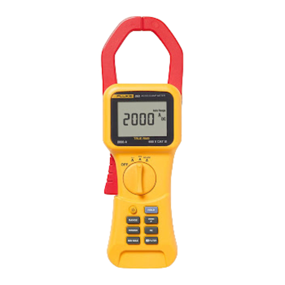
Clamp Meter Introduction Contacting Fluke The Fluke 353 and 355 are hand-held battery-operated To contact Fluke, call one of the following telephone Clamp Meters (the Meter). Both Meters measure ac, dc numbers: true rms, inrush current and frequency; The 355 also USA: 1-888-99-FLUKE (1-888-993-5853) measures ac, dc, true rms voltage, and resistance. -
Page 10: Safety Information
353/355 Users Manual When measuring current, center the Safety Information conductor in the clamp. See Figure 1. Do not apply more than the rated voltage, XWWarnings: Read First as marked on the Meter, between the To avoid possible electric shock or personal terminals or between any terminal and earth ground. - Page 11 Clamp Meter Safety Information Do not operate the Meter around To avoid false readings that can lead to explosive gas, vapor, or dust. electrical shock and injury, replace the When using probes, keep fingers behind battery as soon as the low battery the finger guards.
-
Page 12: Explanation Of Symbols
Earth Ground Alternating Current Direct Current Do not dispose of this product as unsorted municipal waste. Go to Fluke’s web site for recycling information. Conforms to requirements of European Union and European Free Trade Conforms to relevant Australian standards N10140... -
Page 13: Features
Clamp Meter Features Table 2. Features and Buttons Features See Figure 1 and Tables 2 and 3 for a list of features. Number Description Current sensing clamp Rotary function switch Hold button- freezes the display reading and releases the reading when pressed a second time Zero button- Clears last reading from the display and establishes a baseline for ac + dc and dc... -
Page 14: Rotary Switch Positions
353/355 Users Manual Table 2. Features and Buttons (cont.) Table 3. Rotary Switch Positions Number Description Rotary Switch Position 353/355 Backlight button - Turns the backlight on and off. Position Function Position Function The backlight goes off after 5 minutes. Meter is powered AC current down... -
Page 15: Display
Clamp Meter Features Table 4. Display Display Item Explanation Figure 2 and Table 4 explain the display. Zero mode is active Low pass filter is active Hold mode is active Min Max mode is active Min, Max, Avg, or Live modes. Live mode is active with Min Max and designates the real- MAXMINAVGLIVE time reading. -
Page 16: Using The Meter
353/355 Users Manual XWWarning Using the Meter To avoid possible electric shock or personal XW Warning injury, if current is moving in opposite To avoid electric shock or personal injury: directions, place only ONE conductor into When measuring current, center the the clamp at a time. -
Page 17: Measuring Inrush Current
Clamp Meter Using the Meter Measuring Inrush Current Inrush current is surge current that occur when an electrical device is first powered on. Once the device has reached its normal working condition, the current stabilizes. See Figure 4. To capture the inrush current reading: AC/DC CLAMP METER AC/DC CLAMP METER With the system under test powered down, place the... -
Page 18: Measuring Ac And Dc Voltage (355 Only)
353/355 Users Manual Measuring AC and DC Voltage (355 only) To measure ac or dc voltage: Turn the rotary function switch to W, V, or X. Connect the black test lead to the COM terminal and the red test lead to the V terminal. Before connecting the probes to the measurement points, add any clips to the probes that are necessary. - Page 19 Clamp Meter Using the Meter AC/DC CLAMP METER Auto Range TRUE RMS 2000 A 600 V CAT AC+DC AC+DC AC+DC HOLD ZERO RANGE INRUSH MIN MAX FILTER 600 V CAT 1000 V CAT fbq06.eps Figure 6. DC Voltage Measurement...
-
Page 20: Testing Continuity (355 Only)
353/355 Users Manual Testing Continuity (355 only) XW Warning To avoid electrical shock when testing continuity in a circuit, make sure the power AC/DC CLAMP METER AC/DC CLAMP METER to the circuit is turned off and all capacitors Auto Range Auto Range are discharged. -
Page 21: Measuring Resistance (355 Only)
Clamp Meter Using the Meter Measuring Resistance (355 only) XW Warning To avoid possible electric shock or personal injury, when measuring resistance in a circuit, make sure the power to the circuit is turned off and all capacitors are discharged. AC/DC CLAMP METER To measure resistance: Auto Range... -
Page 22: Maintenance
Observe correct polarity when installing the batteries. Close the back cover and tighten the screw. User Replaceable Parts Refer to Contacting Fluke for more information. C43 Soft carrying case TL224 1.5 m silicone rubber test leads TP2 Test Probes... -
Page 23: Specifications
Clamp Meter Specifications Specifications Electrical Specifications Current Measurement 10 Hz to 100Hz Trigger Level Trigger Level Trigger Level for for Hz for Hz Range Resolution Accuracy, A Inrush Filter OFF Filter ON 40 A 10 mA 1.5 % rdg + 15 digits 0.50 A 2.50 A 0.50 A... - Page 24 353/355 Users Manual Voltage Measurement (355 only) 10 Hz to 100 Hz 600 and 1000 V ranges have 10 % over range to 660 and 1100 V respectively. Trigger Level for Hz Trigger Level for Hz Range Resolution Accuracy Filter OFF Filter ON 1 mV 1 % rdg + 10 digits...
- Page 25 Clamp Meter Specifications Continuity Beeper (355) General Specifications On at Batteries: 6- 1.5 V AA NEDA 15 A or IEC LR6 Off at Test Leads: Rated to 1000 V Weight: 1.8 lb (.814 kg) Frequency Measurement Jaw Size: 2.28 inches (58 mm) Measurement Range 5.0 Hz to 1 kHz Dimensions (L x W x D): 12 inches x 3.75 inches x...
-
Page 26: Standards And Agency Approval Specifications
353/355 Users Manual Standards and Agency Approval Specifications Environmental Specifications 32 °F to + 122 °F Design Operating EN61010-032 CAT IV 600 V, Standards and Temperature (0 °C to +50 °C) IEC/EN 61326-1:1997 Compliance -4 °F to 140 °F Storage Temperature P, ), ;, ~ (-20 °C to +60 °C)
Need help?
Do you have a question about the 353 and is the answer not in the manual?
Questions and answers