Advertisement
Quick Links
Advertisement

Related Manuals for Fluke 323


Summary of Contents for Fluke 323
- Page 1 323/324/325 Clamp Meter Calibration Manual...
- Page 2 323/324/325 Calibration Manual Safety Information A Warning identifies conditions and procedures that are dangerous to the user. A Caution identifies conditions and procedures that could cause Product damage, equipment under test damage, or permanent loss of data. Table 1 shows the symbols used on the Product and in this manual.
- Page 3 Clamp Meter Safety Information • Connect the common test lead before the live test lead and remove the live test lead before the common test lead. • Remove all probes, test leads, and accessories before the battery door is opened. •...
- Page 4 Control Instrumentation” product. Do not CAT IV at the source of the building’s dispose of this product as unsorted low-voltage MAINS municipal waste. Go to Fluke’s website for installation. recycling information. Note This product complies with the Regulation for the Administration of the...
- Page 5 323 ............. 0.1 A 324, 325 ..........(0.01, 0.1) A Accuracy 323, 325 ..........2.0 % ±5 digits (45 - 65 Hz) 2.5 % ±5 digits (65 - 400 Hz) 324 ............ 1.5 % ±5 digits (45 Hz to 400 Hz)
- Page 6 Note: Temperature uncertainty (accuracy) does not include error of the thermocouple probe. Mechanical Specifications Size (L x W x H) ........(207 x 75 x 34) mm Weight 323 ............. 265 g 324 ............. 208 g 325 ............. 283 g Environmental Specifications Operating Temperature ......
- Page 7 Clamp Meter Maintenance Maintenance Clean the Product Caution To prevent possible damage to the Product or to equipment under test, do not use abrasive cleaners. They will damage the case. Regularly wipe the case with a damp cloth and weak detergent. To clean the Product Jaw: 1.
- Page 8 User-replaceable parts are shown in Table 2. Table 2. User-Replaceable Parts Fluke Part Description Number 3986568 FLUKE-CAP-2001,TL7X PROBE CAP,BLACK 3986579 FLUKE-CAP-2001-01,TL7X PROBE CAP,FLUKE RED 2838018 BATTERY 1.5V LR03 ALKALINE AAA 4146344 BATTERY DOOR 4166286 SOFT CASE BLACK/YELLOW VINYL 4045153 323/324/325 USERS MANUAL...
- Page 9 2. Turn the rotary switch on while you hold down the button. All of the display segments are shown. See Figure 3. If segments of the display are missing, repair is necessary. See “Contact Fluke”. hfk001.eps Figure 3. Display Segments (324 and 325 Display is Shown)
- Page 10 1. With the Product on, push . The backlight will come on. 2. Push again to turn the backlight off. 3. If the backlight does not function correctly, repair is necessary. See “Contact Fluke”. Button Test To verify that the buttons function, turn on the Product and push each button separately.
- Page 11 Clamp Meter Performance Tests Temperature, Volts, Ohms, Frequency, and Capacitance To do the temperature, volts, ohms, and capacitance performance tests: 1. Connect the Calibrator NORMAL output and ground to the Product. See Figure 4 for the connections. 2. Apply the values shown in Table 4. If the Product shows indications outside of the limits shown in Table 4, calibration adjustment is necessary.
- Page 12 323/324/325 Calibration Manual Current To do the current tests: 1. Connect the Calibrator current output and ground to the 50-Turn Coil. See Figure 5. 2. Turn the Product to the necessary current mode. 3. Apply the input level for each step shown in Table 4.
- Page 13 Clamp Meter Performance Tests Table 4. Performance Tests Test Meter Reading Limit Calibrator (Switch Output High Position) -5 °C -5.8 °C -4.2 °C 0 °C -0.8 °C 0.8 °C Temperature 100 °C 98.2 °C 101.8 °C 400 °C 395.2 °C 404.8 °C 10 V @ 50 Hz 9.3 V...
- Page 14 323/324/325 Calibration Manual Table 4. Performance Tests (cont.) Test Meter Reading Limit Calibrator (Switch Output High Position) 0.12 A @ 50 Hz 5.4 A 6.6 A 0.48 A @ 150 Hz 22.9 A 25.1A 4.2 A @ 50Hz 205.3 A 214.7 A...
- Page 15 Set the Calibrator to Standby after you complete adjustment of each function. Notes For 323, if any calibration point is missing “Err” is shown on the display. After you push the HOLD button, wait until the calibration step number advances before you change the calibrator source. Some adjustment steps can take several seconds to execute before the Product goes to the subsequent step.
- Page 16 323/324/325 Calibration Manual 324 and 325 CAL Keypad 323 CAL Keypad Battery Contacts hfk03.eps Figure 6. Short the CAL Keypad...
- Page 17 Clamp Meter Calibration Adjustment Table 5. Calibration Adjustment Test LCD Reading Calibrator Output (Switch Position) C-1.1 1.05 V, 50 Hz C-1.2 40 V, 50 Hz AC Volts C-1.3 10 V, 50 Hz C-1.4 300 V, 50 Hz DC Volts C-2.2 400 V 400 Ω...
- Page 18 323/324/325 Calibration Manual Table 8. Calibration Adjustment (cont.) Test LCD Reading Calibrator Output (Switch Position) 324 and 325 0.1 μF C-15 0.5 μF C-16 1.5 μF C-17 Capacitance 110 μF C-18 500 μF C-19 1000 μF C-20 C-24 0.8 A, 50 Hz C-25 0.8 A, 100 Hz...
- Page 19 Clamp Meter Temperature Zero Procedure (324 and 325) Temperature Zero Procedure (324 and 325) 1. Turn off the Product and wait 20 minutes. 2. Connect a K-type thermocouple connector from the Calibrator to the Product. 3. After 20 minutes, with the Product still connected to the 3.0 V, turn on the Product and short across the CAL keypad on the pca.
- Page 20 323/324/325 Clamp Meter Users Manual...
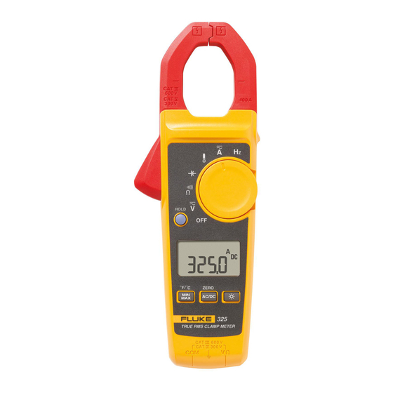
- Page 21 Introduction The Fluke 323/324/325 Clamp Meter (the Product) measures ac and dc voltage, ac current, resistance, and continuity. The 324 and 325 can also measure capacitance and contact temperature. The 325 can also measure dc current and frequency. Note that the 325 is shown in all of the illustrations.
- Page 22 323/324/325 Users Manual Safety Information A Warning identifies conditions and procedures that are dangerous to the user. A Caution identifies conditions and procedures that can cause damage to the Product or the equipment under test. Table 1 tells you about symbols used on the Product and in this manual.
- Page 23 Clamp Meter Safety Information Warning To prevent possible electrical shock, fire, or personal injury: • Use the Product only as specified, or the protection supplied by the Product can be compromised. • Use only correct measurement category (CAT), voltage, and amperage rated probes, test leads, and adapters for the measurement.
- Page 24 323/324/325 Users Manual • Do not apply more than the rated voltage, between the terminals or between each terminal and earth ground. • Comply with local and national safety codes. Use personal protective equipment (approved rubber gloves, face protection, and flame- resistant clothes) to prevent shock and arc blast injury where hazardous live conductors are exposed.
- Page 25 Clamp Meter Safety Information • Connect the common test lead before the live test lead and remove the live test lead before the common test lead. • Remove all probes, test leads, and accessories before the battery door is opened. •...
- Page 26 323/324/325 Users Manual • Remove batteries to prevent battery leakage and damage to the Product if it is not used for an extended period. • Remove batteries to prevent battery leakage and damage to the Product if is to be stored above its operating temperature.
- Page 27 Clamp Meter Symbols Symbols Table 1. Symbols Symbol Meaning Symbol Meaning AC (Alternating Current) Earth DC (Direct Current) AC and DC Current Conforms to European Union WARNING. RISK OF DANGER. directives. Consult user documentation. Battery WARNING.
- Page 28 323/324/325 Users Manual Table 1. Symbols (cont.) Symbol Meaning Symbol Meaning Measurement Category II is applicable to test and MEASUREMENT CATEGORY III is measuring circuits connected applicable to test and measuring directly to utilization points circuits connected to the distribution ...
- Page 29 Clamp Meter How to Clean the Product Note The Measurement Category (CAT) and voltage rating of combinations of test probes, test probe accessories, current clamp accessories, and the Product is the LOWEST rating of individual components. How to Clean the Product Regularly wipe the case with a damp cloth and weak detergent.
- Page 30 Specifications Maximum voltage between any Terminal and Earth Ground ....600 V Range 323 ............ 400.0 A 324, 325 ..........(40.00, 400.0) A Batteries ..........2 AAA, NEDA 24A, IEC LR03 Operating Temperature ......-10 °C to +50 °C Storage Temperature ......-30 °C to +60 °C Operating Humidity .........
- Page 31 Clamp Meter Specifications Weight 323 ............. 265 g 324 ............. 208 g 325 ............. 283 g Safety ............IEC 61010-1, Pollution Degree 2 IEC 61010-2-032: CATIV 300V / CATIII 600V IEC 61010-2-033:CAT IV 300V / CAT III 600V IP Rating ..........IEC 60529: IP30, non-operating...
- Page 32 323 ............ 0.1 A 324, 325 ..........(0.01, 0.1) A Accuracy 323, 325 ..........2.0 % ±5 digits (45 – 65 Hz) 2.5 % ±5 digits (65 – 400 Hz) 324 ............ 1.5 % ±5 digits (45 Hz to 400 Hz) Note Add 2 % for position sensitivity.
- Page 33 Range ............ 600.0 V Resolution ..........0.1 V Accuracy ..........1 % ± 5 digits Resistance Range 323, 324 ..........(400.0, 4000) Ω 325 ............. (400.0, 4000, 40000) Ω Resolution ..........(0.1, 1, 10) Ω Accuracy ..........1 % ±5 digits...
- Page 34 323/324/325 Users Manual Continuity Beeper 323 ............ ≤70 Ω 324/325 ..........≤30 Ω Capacitance (324, 325) Range............(100.0, 1000) μF Resolution ..........(0.1, 1) μF Accuracy ..........1 % ±4 digits Frequency with Jaw (325) Range............5.0 to 500.0 Hz Resolution ..........
- Page 35 Clamp Meter The Meter The Meter...
- Page 36 323/324/325 Users Manual MAXMIN 324/325 gtq001.eps...
- Page 37 Clamp Meter The Meter 2:00 2:00...
- Page 38 323/324/325 Users Manual 600 V 600 V 300 V 300 V 323, 324 TRUE RMS CLAMP METER TRUE RMS CLAMP METER 600 V 300 V 600 V 300 V...
- Page 39 Clamp Meter The Meter 323 V dc - 323 V ac - 324, 325 V dc & V ac - >30 V 300 V...
- Page 40 323/324/325 Users Manual 600 V 600 V 300 V 300 V TRUE RMS CLAMP METER TRUE RMS CLAMP METER 600 V 600 V 300 V 300 V <70 324/325 <30...
- Page 41 Clamp Meter The Meter HOLD TRUE RMS CLAMP METER 600 V 300 V > 30 V 20 V AC/DC & ZERO ZERO ZERO ZERO 2 sec AC/DC AC/DC AC/DC...
- Page 42 323/324/325 Users Manual 324, 325 TRUE RMS CLAMP METER 600 V 300 V...
- Page 43 Clamp Meter The Meter Learn more about measuring tools on our website.
Need help?
Do you have a question about the 323 and is the answer not in the manual?
Questions and answers