3Com 3C13701 Installation Manual
5000 series
Hide thumbs
Also See for 3C13701:
- Module manual (187 pages) ,
- Quick reference manual (162 pages) ,
- Installation manual (104 pages)
Table of Contents
Advertisement
Quick Links
Download this manual
See also:
Quick Reference Manual
Advertisement
Table of Contents
Troubleshooting

Related Manuals for 3Com 3C13701


Summary of Contents for 3Com 3C13701
- Page 1 ® 3Com Router 5000 Family Installation Guide Router 5012 (3C13701) Router 5232 (3C13751) Router 5682 (3C13701) www.3Com.com Part Number: 10015619 Rev. AB Published: June 2007...
- Page 2 LICENSE.TXT or !LICENSE.TXT. If you are unable to locate a copy, please contact 3Com and a copy will be provided to you.
-
Page 3: Table Of Contents
Organization of the Manual Conventions Related Documentation VERVIEW Introduction Types of SICs Types of MIMs YSTEM PECIFICATIONS 3Com Router Router 5012 3Com Router 5232 3Com Router Router 5682 NSTALLATION REPARATION Requirements on Environment Precautions Tools, Meter and Devices NSTALLATION OF THE... - Page 4 ONTENTS OUTER AINTENANCE Software Maintenance Hardware Maintenance ROUBLESHOOTING Troubleshooting of the Power System Troubleshooting of the Console Terminal Troubleshooting of SDRAM Application Software Upgrade...
-
Page 5: About This Guide
Release Notes before installing the router in your network. If the information in the Release Notes differ from the information in this guide, follow the instructions in the Release Notes. Organization of the The 3Com ® Router 5000 Family Installation Guide consists of the following Manual chapters: Overview—Provides a brief overview of the main features of the Router 5000... -
Page 6: Related Documentation
This manual provides information about the Smart Interface Cards (SICs), Multi-Functional Interface Modules (MIMs), and Flexible Interface Cards (FICs) associated with this release. Most user guides are available in Adobe Acrobat Reader Portable Document Format (PDF) or HTML on the 3Com World Wide Web site: http://www.3com.com/... -
Page 7: Overview
Introduction 3Com 5000 Routers are intended for use on enterprise-level networks. Depending on the network size, 3Com 5000 Routers can either be core routers on small and medium enterprise networks, or access routers for network branches on some large-sized enterprise networks. Therefore, 3Com 5000 Routers are suitable for the application on the carrier-level networks, such as telecom management networks and billing networks. - Page 8 CT1/PRI interface can connect the E1 or T1 interface of switches, as well as communicating with the gatekeeper (GK). With high-speed CPU and digital signal processing (DSP) technology, 3Com 5000 Routers can provide voice over IP (VoIP) services with high quality voice. They can drive down the cost of long distance communications between main office and branches in enterprise deployment.
-
Page 9: Types Of Sics
Types of SICs Types of SICs 3Com 5000 Router Family provides two SIC slots which can accept the following types of SICs for this release: Voice Interface Card Router 1-port FXS SIC card (3C13725) ■ Router 2-port FXS SIC card (3C13726) ■... - Page 10 1: O HAPTER VERVIEW...
-
Page 11: System Specifications
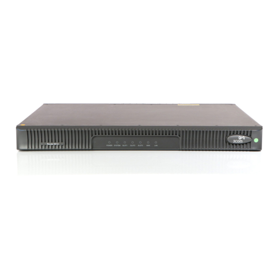
YSTEM PECIFICATIONS 3Com Router Router 5012 Appearance Figure 1 Front view of 3Com Router 5012 1) Power 2) SYSTEM 3) SLOT1 4) SLOT2 5) SLOT3 6) WAN 7) LAN Figure 2 Rear view of 3Com Router 5012 1) Power switch... - Page 12 2: S HAPTER YSTEM PECIFICATIONS Panel LEDs Eight LEDs are provided on 3Com Router 5012. Their meaning is explained in the following table: Table 2 LEDs of 3Com Router 5012 Indication POWER System power LED: OFF means power is off, ON means power is on.
-
Page 13: 3Com Router 5232
5) Fixed WAN interface (WAN0) 6) MIM SLOT1 7) MIM SLOT2 8) MIM SLOT3 Panel LEDs 10 LEDs are provided on the 3Com Router 5232. Their meaning is explained in the following table: Table 4 LEDs of 3Com Router 5232 Indication POWER System power LED: OFF means power is off, ON means power is on. - Page 14 Indicating the slot number. Ethernet interface LED: Green means the interface is normal. Blinking yellow means data is being transceived over the Ethernet. System Description Table 5 System description of 3Com Router 5232 Item 5232 Fixed interface One AUX port...
-
Page 15: 3Com Router Router 5682
3Com Router Router 5682 3Com Router Router 5682 Appearance Figure 5 Front view of 3Com Router 5682 1) POWER 2) SYSTEM 3) AUX 4) CON 5) SLOT0~7 (READY/ACTIVE) Figure 6 Rear view of 3Com Router 5682 1) Power switch 2) Power socket... - Page 16 2: S HAPTER YSTEM PECIFICATIONS Panel LEDs 18 LEDs are provided on 3Com Router 5682. Their meaning is explained in the following table: Table 6 LEDs of 3Com Router 5682 Indication POWER System power LED: OFF means power is off. ON means power is on. As for the router with AC/DC power supply, OFF means it is not powered on, ON means it is powered on.
-
Page 17: Installation Preparation
NSTALLATION REPARATION Requirements on 3Com 5000 Routers must be used indoors. To ensure the normal operation and prolong Environment their service life, the following requirements for installation site must be met. Requirements on Certain requirements on temperature and humidity in the equipment room shall be met. - Page 18 0.006 0.05 0.01 Requirements on Although many anti-static considerations have been given to 3Com 5000 Routers, Electrostatic damage to the router’s circuit or even the whole equipment may still happen when the Discharge Prevention static electricity exceeds the tolerance threshold.
-
Page 19: Precautions
■ arrester could be installed at the input end of the power supply. As for the signal line outdoors to which the interface modules of 3Com 5000 Routers ■ are connected (such as an ISDN line, telephone line, E1/T1 line, etc.) a special lightning arrester should be installed at the input end of the signal line to enhance the lightning protection capability. -
Page 20: Tools, Meter And Devices
3: I HAPTER NSTALLATION REPARATION Tools, Meter and 3Com 5000 Routers are not shipped with installation tools. Assemble the following items Devices prior to installation: Tools Phillips screwdriver ■ Straight screwdriver ■ ESD-preventive wrist strap ■ Cables PGND wire and power cord ■... -
Page 21: Installation Of The Router
NSTALLATION OF THE OUTER Installation Process Figure 7 3Com 5000 Router installation process Start Install the Router to the specified location Connect PGND Connect power cord Connect the Router to Console terminal Check Power on Troubleshooting Normal? Power off Power off and disconnect... -
Page 22: Installing The Router To The Specified Location
Do not place heavy objects on the router. ■ Installing the Router 3Com 5000 Routers are designed according to the dimensions of a 19-inch standard in a Rack rack. As shown in Figure 8, follow the steps below to install the router: 1 Check the grounding and stability of the rack. -
Page 23: Connecting The Pgnd Wire
Therefore, you must correctly connect the PGND wire before installing and using the device. The power input end of 3Com 5000 Routers is connected to a noise filter. The neutral point of the noise filter is directly connected to the chassis and is called protection ground (PGND). -
Page 24: Connecting The Power Cord
4: I HAPTER NSTALLATION OF THE OUTER Connecting the Two types of 3Com 5000 Routers are provided: Power Cord AC-powered ■ DC-powered ■ Except for the input power, these two types have exactly the same features and functions. Power Input and... - Page 25 Connecting the Power Cord Connection of AC Power Cord 1 Confirm that the PGND wire is correctly connected. 2 Make sure that the power switch for the router is placed in the OFF position. Then, connect one end of the power cord, which came with the device, to the power socket on the rear panel of the router chassis, and the other end to the AC power outlet.
- Page 26 4: I HAPTER NSTALLATION OF THE OUTER Connection of the DC Power Cord The DC power cords consist of one –48V blue power cord and one black PGND wire that are bound together. Figure 13 DC power cord TO BGND TO BGND TO -48V TO -48V...
-
Page 27: Connecting Console Terminal
Connecting Console Introduction to Console Port Terminal 3Com 5000 Router provides an RS232 asynchronous serial console (CON) port, through which configuration of the router can be performed. For the attributes of the console port, refer to Table 13. Table 13 Attributes of the console port... -
Page 28: Connecting Router To The Lan
NSTALLATION OF THE OUTER Connecting Router Introduction to the Ethernet Interface to the LAN 3Com 5000 Routers provide fixed 100BASE-TX FE interface(s). For the interface attributes, refer to Table 14. Table 14 Attributes of the Ethernet interface Attribute Description Connector... -
Page 29: Connecting Router To The Wan
2 Please check the LAN LED on front panel of the Router. ON means the link is connected. Connecting Router 3Com 5000 Routers provide multiple types of WAN interfaces, and the fixed WAN to the WAN interfaces include an AUX port and a WAN interface (synchronous/asynchronous serial interface). - Page 30 4: I HAPTER NSTALLATION OF THE OUTER Figure 17 AUX cable assembly Connection of the AUX cable Follow these steps to connect the AUX cable: 1 Plug the RJ45 connector of the AUX cable into the AUX port of the router. 2 Connect the DB25 or DB9 connector of the AUX cable to the serial interface of the analog Modem.
- Page 31 Interface to DSU/CSU Introduction to the Synchronous/Asynchronous Serial Interface. The fixed WAN interface of 3Com 5000 Routers is a synchronous/asynchronous serial interface, which is usually used for the connection with a WAN device, such as a Modem or CSU/DSU. It can operate in the synchronous/asynchronous mode or DTE/DCE mode, depending on the application.
- Page 32 4: I HAPTER NSTALLATION OF THE OUTER Table 17 Transmission rate and transmission distance of V.24 (RS232)/V.35 cable V.24 (RS232) V.35 Maximum transmission Maximum transmission Baud rate (bps) distance (m) Baud rate (bps) distance (m) 2400 2400 1250 4800 4800 9600 9600 19200...
- Page 33 Connecting Router to the WAN The following figures show the cable assembly of all these types: V.24 (RS232) DTE cable assembly ■ Figure 18 V.24 (RS232) DTE cable assembly V.24 (RS232) DCE cable assembly ■ Figure 19 V.24 (RS232) DCE cable assembly...
- Page 34 4: I HAPTER NSTALLATION OF THE OUTER V.35 DTE cable assembly ■ Figure 20 V.35 DTE cable assembly V.35 DCE cable assembly ■ Figure 21 V.35 DCE cable assembly...
- Page 35 Connecting Router to the WAN X.21 DTE cable assembly ■ Figure 22 X.21 DTE cable assembly X.21 DCE cable assembly ■ Figure 23 X.21 DCE cable assembly The synchronous/asynchronous series interface matches a DB28 connector, and current these types of synchronous/asynchronous series interface cables are supported: V.24 (RS232) DTE cable: DB25 (male) connector ■...
- Page 36 4: I HAPTER NSTALLATION OF THE OUTER V.24 DCE cable assembly ■ Figure 25 V.24 DCE cable assembly V.35 DTE cable assembly ■ Figure 26 V.35 DTE cable assembly V.35 DCE cable assembly ■ Figure 27 V.35 DCE cable assembly X.21 DTE cable assembly ■...
- Page 37 Connecting Router to the WAN X.21 DCE cable assembly ■ Figure 29 X.21 DCE cable assembly CAUTION: The aforementioned cables are optional, so you have to order them when purchasing the router if needed. Connection of Synchronous/Asynchronous Serial Cable Follow the steps below to connect the synchronous/asynchronous cable (taking the connection from WAN to DSU/CSU as an example): CAUTION: Do not hot swap the synchronous/asynchronous cable.
- Page 38 4: I HAPTER NSTALLATION OF THE OUTER E1 Interface Cable E1 interface cable, which is G.703-compatible, may be 75Ω unbalanced coax cable or 120Ω balanced twisted pair cable. unbalanced coax cable 75Ω ■ Figure 30 E1 75Ω unbalanced coax cable Ω...
- Page 39 Connecting Router to the WAN Connecting E1 Interface Cable CAUTION: Examine the interface mark before connection to avoid cable mis-insertion and router ■ damage. When the E1 interface cable is routed outdoors, you need use the special lightning ■ protection unit at the input end to prevent possible damage. 1 Check the E1 cable type and choose correct impedance value of the E1 interface through the inverter switch.
- Page 40 4: I HAPTER NSTALLATION OF THE OUTER If you choose two RJ45 connectors (for extending E1 interface cables), connect the RJ connector of the 120Ω balanced twisted pair cable to a network connector assembly, which is connected to a 120Ω E1 trunk cable. The 120Ω E1 trunk cable is then connected to the peer device.
- Page 41 Connecting Router to the WAN You can also choose to use network connector assembly, for extending two T1 interface cables. T1 interface cable and network connector assembly are optional. Connecting T1 Interface Cable CAUTION: Examine the interface mark before connection to avoid cable mis-insertion and router ■...
-
Page 42: Connecting Router To A Voice Device
HAPTER NSTALLATION OF THE OUTER Connecting Router The optional interface cards/interface modules on 3Com 5000 Router also provides many to a Voice Device types of voice interfaces. Checking After the During the installation of the router, it is necessary to perform the following installation... -
Page 43: Tartup And
TARTUP AND ONFIGURATION OF THE OUTER Startup of the You can only configure the router through the console port if it is the first time you use it. Router Setting up Connecting the Router to a Console Terminal Configuration To set up the local configuration environment, the RJ-45 connector of the console cable Environment needs to be connected to the console port on the router, and the DB-25 or DB-9 connector to the serial interface of a PC. - Page 44 5: S HAPTER TARTUP AND ONFIGURATION OF THE OUTER Setting Terminal Parameters Follow these steps to set the parameters of the Hyper Terminal in Windows98: 1 Select a connection port. Select the serial interface to be connected in the [Connect using] box, as shown in Figure 37.
- Page 45 Startup of the Router 2 Set the serial interface parameters. As shown in Figure 38, in the properties dialog box of the serial interface, set the baud rate to 9600, data bit to 8, no parity check, stop bit to 1, and flow control to none.
- Page 46 Press Ctrl-B to enter Boot Menu Press <Ctrl+B> and the system will enter the Boot menu. Otherwise, the system will enter the program decompression process. After “3Com 5000 Router Boot ROM, V9.13” appears, “3Com start booting, (V2.00)” ■ will disappear immediately.
-
Page 47: Configuration Fundamentals Of The Router
Starting at 0x10000... User interface Con 0 is available. Press ENTER to get started. Press <Enter> and the screen will display: <3Com> This prompt indicates that the router has entered the system view, and now the router can be configured. Configuration... - Page 48 Command Line Characteristics of the Command Line Interface Interface The command line interface of 3Com 5000 Routers provides a number of configuration commands, which can be used to configure and manage the router. The command line interface has the following characteristics: Performs the local configuration through CON port.
-
Page 49: Router Maintenance
Uploading/downloading the application image and configuration file through FTP ■ 3Com 5000 Routers are loaded initially. You may need to upgrade it and its corresponding Boot ROM image to accommodate new product features. Examine the current version of the application and Boot ROM program before software upgrade. - Page 50 6: R HAPTER OUTER AINTENANCE Software This section describes how to maintain the Boot ROM image using V9.13 as an example. Maintenance Under v 3.0 Environment The entire Boot ROM image file in this section includes two segments: extended and basic.
- Page 51 Software Maintenance The following table gives default names and types of the boot files. Table 20 Default names and types of the boot files Boot file File name File type Main boot file main.bin Backup boot file backup.bin Secure boot file secure.bin Note that: The application images for system boot can be type M, B and S, but not type N/A.
- Page 52 6: R HAPTER OUTER AINTENANCE To use a.bin as the main boot file, select <1> in this menu. Upon validation of the setting, the file type of the original main boot file changes to N/A. Now, the a.bin file is the first boot file.
- Page 53 Software Maintenance 8 Enter debugging environment in case of faults. 9 Enter the Boot ROM operation menu. Select <9> to enter Boot ROM Download Menu as follows for upgrade, backup, or recovery: Boot ROM Download Menu: Download Boot ROM with XModem Download Extended Segment of Boot ROM with XModem Restore Extended Segment of Boot ROM from FLASH Backup Extended Segment of Boot ROM to FLASH...
- Page 54 6 After completing download, the system begins writing to Flash memory and upon its completion outputs the following information: Download completed. For an 3Com 5000 router, the system also prompts you to select file type upon completion of downloading. please select file to be saved as 1.
- Page 55 Software Maintenance Upgrading the Entire Boot ROM Image 1 Enter Boot Menu, and select <9> to enter Boot ROM Download Menu as follows: Boot ROM Download Menu: Download Boot ROM with XModem Download Extended Segment of Boot ROM with XModem Restore Extended Segment of Boot ROM from FLASH Backup Extended Segment of Boot ROM to FLASH Exit to Main Menu...
- Page 56 TFTP or FTP Client and needs connecting to TFTP or FTP Server using a fixed Ethernet interface. CAUTION: No TFTP/FTP Server is available with the 3Com 5000 Routers. You must install one yourself. 1 Start TFTP or FTP Server on the PC connected to the Ethernet interface on the router and set the path for getting the source file.
-
Page 57: Hardware Maintenance
The router can serve as FTP Server when loading v 3.0. You can run FTP Client to upload or download the files of application image, Boot ROM image, and configuration. Hardware Maintenance Required Tools Installation tools are not provided with the 3Com 5000 Routers. You must have the following tools available. Phillips screwdriver ■ Flat-blade screwdriver ■... - Page 58 2) Chassis bottom 3) Fastening screw CAUTION: On a mounting screw of your router chassis, there is an anti-dismantle seal of 3Com ■ Corporation. You must keep it in good condition when asking your sales agent for servicing. You can open the chassis yourself but with permission of your sales agent and must operate following the related rules.
- Page 59 The existing SDRAM is damaged. ■ You can see this banner at boot: Router starts booting ... (V2.00) *********************************************** 3Com 5000 Routers Boot ROM, V9.13 * *********************************************** Copyright(C) 1997-2003 by 3Com Corporation. Testing memory...OK! 128M bytes...
- Page 60 Extendable to 256MB Extendable to 256MB at any at the original memory or both of the memory slots slot The following figure shows the position of the SDRAM on the 3Com Router. Figure 42 Position of the SDRAM on the 3Com Router...
- Page 61 Hardware Maintenance The following figure shows the position of the SDRAM on the 3Com Router 5232. Figure 43 Position of the SDRAM on the 3Com 5232 To ensure you can install the SDRAM correctly, there are two clips In the SDRAM slot matching two concave points in the SDRAM card.
- Page 62 6: R HAPTER OUTER AINTENANCE Installing the SDRAM 1 Locate the position of the SDRAM slot. 2 Take out a new SDRAM. Hold the SDRAM by its top edge and put it into the SDRAM slot in correct orientation. 3 Press the SDRAM down into the slot with appropriate pressure, and close the locking spring clips at both sides of the slot until the pins at both ends of the clip snap into the notches at both sides of the SDRAM.
-
Page 63: Troubleshooting
ROUBLESHOOTING Troubleshooting of Fault: the Power System POWER LED is OFF or blinking. Troubleshooting: Check: Whether the power switch of the router is turned on. ■ Whether the power supply switch is turned on. ■ Whether the power cord of the router is properly connected. ■... -
Page 64: Troubleshooting Of Sdram
If you are sure that the power system and configuration system have no faults, please contact the agent of 3Com Corporation Co., Ltd. With his consent, open the chassis to check whether the SDRAM has become loose. If that is the case, you may remove and reinstall the SDRAM. -
Page 65: Application Software Upgrade
Press <Enter> key when ready. Troubleshooting: 3Com 5000 Routers should be loaded with different application software versions. The problem described above is likely to result from a mismatch between the application software version and the router model. In this case, contact your agent to obtain the... - Page 66 7: T HAPTER ROUBLESHOOTING If the improper software has been loaded, the Router cannot start or work correctly. In this case, select XModem or TFTP mode in the boot menu to restore/upgrade the software version (FTP upgrade mode cannot be used here). If similar symptoms present when upgrading the software with other approaches, solve the problem with reference to this example.
Need help?
Do you have a question about the 3C13701 and is the answer not in the manual?
Questions and answers