3Com 3C13751 Getting Started Manual
5000 series
Hide thumbs
Also See for 3C13751:
- Module manual (187 pages) ,
- Quick reference manual (162 pages) ,
- Installation manual (104 pages)

Related Manuals for 3Com 3C13751


Summary of Contents for 3Com 3C13751
- Page 1 ® 3Com Router 5000 Family Getting Started Guide www.3Com.com/ Part Number 10015122 Rev. AB Published September 2007 Mfg. BOM 3122A076...
- Page 2 All other company and product names may be trademarks of the respective companies with which they are associated. ENVIRONMENTAL STATEMENT It is the policy of 3Com Corporation to be environmentally friendly in all operations. To uphold our policy, we are committed to: Establishing environmental performance standards that comply with national legislation and regulations.
- Page 3 ® for your 3Com Router Thank you for purchasing a 3Com Router 5000 Family router. As part of our commitment to bringing you the most capable and dependable network equipment, 3Com offers free software maintenance updates and documentation updates on our website.
-
Page 5: Table Of Contents
Conventions Related Documentation Documentation Comments Introducing the Router 5000 Family About the Router 5000 3Com Router 5012 (3C13701) Indicators System Description 3Com Router 5232 (3C13751) Indicators System Description 3Com Router 5642 (3C13755) Indicators System Description 3Com Router 5682 (3C13759) Indicators... - Page 6 Troubleshooting of the Console Terminal Troubleshooting of SDRAM Application Software Upgrade Router Software Maintenance Introduction Software Maintenance under v 3.11 Environment Dealing with a Router Password Loss Obtaining Support for Your 3Com Products Register Your Product to Gain Service Benefits...
- Page 7 Contents Solve Problems Online Purchase Extended Warranty and Professional Services Access Software Downloads Contact Us Telephone Technical Support and Repair...
- Page 8 Contents...
-
Page 9: About This Guide
If the information in the release notes differ from the information in this guide, follow the instructions in the release notes. 3Com Web Site Most user guides and release notes are available in Adobe Acrobat Portable Document Format (PDF) or HTML on the 3Com Web site: www.3Com.com... -
Page 10: Conventions
This manual describes the various modules that are available for use with the Router 5000. Release Notes ■ These notes provide information about the current software release, including new features, modifications, and known problems. The release notes are supplied on the 3Com Web site. -
Page 11: Documentation Comments
Part Number 10015122 Rev. AA Page 21 Please note that we can only respond to comments and questions about 3Com product documentation at this e-mail address. Questions related to technical support or sales should be directed in the first instance to your network supplier. - Page 12 12 About This Guide...
-
Page 13: Introducing The Router 5000 Family
3Com Router 5682 (3C13759) ■ About the The 3Com Router 5000 Family is intended for use on enterprise-level Router 5000 networks. The Router 5000 Family is ideal for use as core routers on small and medium enterprise networks, or access routers for network branches on large-sized enterprise networks. - Page 14 14 Chapter 1: Introducing the Router 5000 Family Multiple interface card/interface module options The Router 5000 provides SIC slots and MIM slots for installing expansion modules including serial interfaces, T1/CT1/PRI interface, E1/CE1/PRI interface, BRI S/T and U interfaces, Ethernet interface (including FE/GE, electrical interface and fiber interface), ADSL/G.SHDSL interface, ATM 25M/155M interface, and so on.
-
Page 15: 3Com Router 5012 (3C13701)
3Com Router 5012 (3C13701) 15 3Com Router 5012 Figure 1 Front view of 3Com Router 5012 (3C13701) 1) POWER 2) SYSTEM 3) SLOT1 4) SLOT2 5) SLOT3 6) WAN 7) LAN Figure 2 Rear view of 3Com Router 5012 1) Power switch... -
Page 16: Indicators
16 Chapter 1: Introducing the Router 5000 Family Indicators Eight indicators are provided on 3Com Router 5012. Their meaning is explained in the following table: Table 2 Router 5012 Indicators Indication POWER System power LED: OFF means power is off, ON means power is on. -
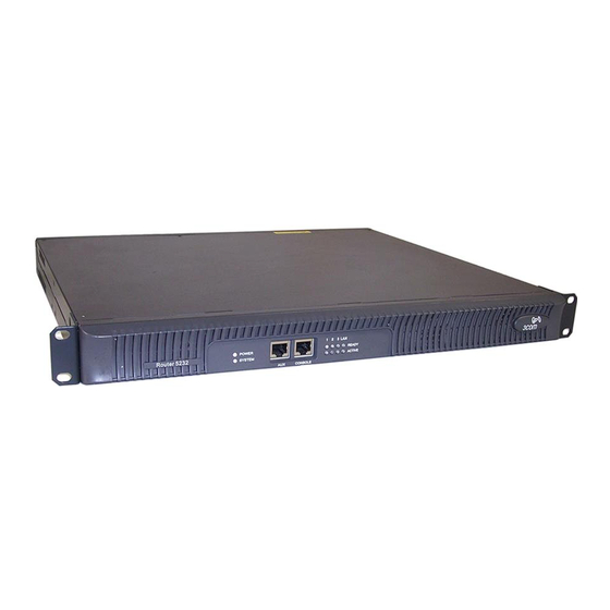
Page 17: 3Com Router 5232 (3C13751)
3Com Router 5232 (3C13751) 17 Table 3 System description of 3Com Router 5012 (continued) Item Description Input voltage Rated voltage range: 100 to 240 VAC, 50 or 60 Hz Max voltage range: 85 to 264 VAC, 47 to 63 Hz... -
Page 18: Indicators
5) Fixed WAN interface (WAN0) 6) MIM SLOT1 7) MIM SLOT2 8) MIM SLOT3 Indicators 10 indicators are provided on 3Com Router 5232. Their meaning is explained in the following table: Table 4 LEDs of 3Com 5232 Router Indication POWER System power LED: OFF means power is off, ON means power is on. -
Page 19: System Description
3Com Router 5232 (3C13751) 19 System Description Table 5 System description of 3Com Router 5232 Item Description Fixed interface One AUX port One console port Two LAN ports Slot 3 MIM slots MPC 8245 300 MHz NVRAM 128 KB Boot ROM... -
Page 20: 3Com Router 5642 (3C13755)
20 Chapter 1: Introducing the Router 5000 Family 3Com Router 5642 Figure 5 Front view of 3Com Router 5642 (3C13755) (3) (4) (5) 1) POWER 2) SYSTEM 3) AUX 4) CON 5) SLOT0~3 (READY/ACTIVE) Figure 6 Rear view of 3Com Router 5642... -
Page 21: System Description
Table 6 Router 5642 Indicators (continued) Indication Ethernet interface LED: Green means the interface is normal. Blinking yellow means data is being transceived over the Ethernet. System Description Table 7 System description of 3Com Router 5642 Item Description Slot 4 MIM slots... -
Page 22: 3Com Router 5682 (3C13759)
22 Chapter 1: Introducing the Router 5000 Family 3Com Router 5682 Figure 7 Front view of 3Com Router 5682 (3C13759) 1) POWER 2) SYSTEM 3) AUX 4) CON 5) SLOT0~7 (READY/ACTIVE) Figure 8 Rear view of 3Com Router 5682 1) Power switch... -
Page 23: Indicators
3Com Router 5682 (3C13759) 23 Indicators 18 LEDs are provided on 3Com Router 5682 Router. Their meaning is explained in the following table: Table 8 Router 5682 Indicators Indication POWER System power LED: OFF means power is off. ON means power is on. - Page 24 24 Chapter 1: Introducing the Router 5000 Family...
-
Page 25: Installation
Installing the Router on a Workbench 25 2 Installation This section describes installation of the router: Installing the router on a workbench ■ Installing the router in a rack ■ Installing the If you are not rack-mounting the router, place it on a clean, sturdy bench Router on a top. -
Page 26: Power Cords, Grounds And Cables
26 Chapter 2: Installation Power Cords, Grounds and Cables PGND Wire WARNING: The normal connection of the PGND wire is an important guard against the lightning and interference. Therefore, the user must first correctly connect the PGND wire before installing and using the device. -
Page 27: Power Cord
Power Cords, Grounds and Cables 27 Use a PGND wire to connect the screw to the earth ground, and the grounding resistance should not be greater than 5-ohm. Likewise, if the router is installed in a 19-inch standard rack, this rack is required to be grounded too. - Page 28 28 Chapter 2: Installation Figure 11 AC Power Connector (1) Power switch (2) AC input receptacle Recommended power outlet The user is recommended to use a single-phase 3-core outlet with a neutral point or a multi-functional computer power socket. The neutral point of the outlet should be grounded reliably.
-
Page 29: Console Terminal
Console Terminal 29 Console Terminal Introduction to console port 3Com 5000 Router provides an RS232 asynchronous serial console (CON) port, through which configuration of the router can be performed. For the attributes of the console port, refer to Table 12. -
Page 30: Router To Lan Connection
30 Chapter 2: Installation Router to LAN Introduction to the Ethernet interface Connection The Router 5000 provide fixed 100BASE-TX FE interface(s). For the interface attributes, refer to Table 13. Table 13 Attributes of the Ethernet interface Attribute Description Connector RJ45 Interface Operating mode 10/100Mbps auto-sensing... -
Page 31: Router To Wan Connection
Router to WAN Connection 31 Router to WAN The Router 5000 provide multiple types of WAN interfaces, and the fixed Connection WAN interfaces include an AUX port and a WAN interface (synchronous/asynchronous serial interface). This section describes the connection of the two interfaces. Connecting the AUX Introduction to the AUX port port to the Modem... -
Page 32: Wan Interface To Dsu/Csu
32 Chapter 2: Installation Figure 14 AUX cable assembly WAN Interface to Introduction to the synchronous/asynchronous serial interface DSU/CSU The fixed WAN interface of the Router 5000 is a synchronous/asynchronous serial interface, which is usually used for the connection with a WAN device, such as a Modem or CSU/DSU. It can operate in the synchronous/asynchronous mode or DTE/DCE mode, depending on the application. - Page 33 Router to WAN Connection 33 Table 15 Attributes of the synchronous/asynchronous serial interface Description Attribute Synchronous Asynchronous Function DDN leased line backup Modem dial-up Terminal access Backup Asynchronous lease line terminal access Protocol SLIP LAPB HDLC X.25 Frame Relay Synchronous/asynchronous mode ■...
- Page 34 34 Chapter 2: Installation CAUTION: The baud rate should not exceed 64kbps when the V.24 cable operates in synchronous mode. DTE and DCE ■ Synchronous serial interface can operate in both DTE and DCE mode. For two devices connected directly, one should operate in DTE mode, and the other should operate in DCE mode.
- Page 35 Router to WAN Connection 35 Figure 15 V.24 (RS232) DTE cable assembly V.24 (RS232) DCE cable assembly ■ Figure 16 V.24 (RS232) DCE cable assembly V.35 DTE cable assembly ■...
- Page 36 36 Chapter 2: Installation Figure 17 V.35 DTE cable assembly V.35 DCE cable assembly ■ Figure 18 V.35 DCE cable assembly X.21 DTE cable assembly ■...
- Page 37 Router to WAN Connection 37 Figure 19 X.21 DTE cable assembly X.21 DCE cable assembly ■ Figure 20 X.21 DCE cable assembly The synchronous/asynchronous series interface matches a DB28 connector, and current these types of synchronous/asynchronous series interface cables are supported: V.24 (RS232) DTE cable: DB25 (male) connector ■...
- Page 38 38 Chapter 2: Installation Figure 21 V24 DTE cable assembly V.24 DCE cable assembly ■ Figure 22 V.24 DCE cable assembly V.35 DTE cable assembly ■ Figure 23 V.35 DTE cable assembly V.35 DCE cable assembly ■...
- Page 39 Router to WAN Connection 39 Figure 24 V.35 DCE cable assembly X.21 DTE cable assembly ■ Figure 25 X.21 DTE cable assembly X.21 DCE cable assembly ■ Figure 26 X.21 DCE cable assembly CAUTION: These cables are optional, and must be purchased in addition to the router.
- Page 40 40 Chapter 2: Installation E1 interface to DSU/CSU Introduction to the E1 interface E1 interface, which stands for channelized CE1/PRI interface, is responsible for forwarding and processing E1 data flow, delivering CE1 access and implementing ISDN PRI function. Its attributes are listed in the following table: Table 17 E1 interface attributes Attribute...
- Page 41 Router to WAN Connection 41 The cable is attached with DB15 (male) connector for the router end, and with RJ45 connector for the network end. See the following figure: Figure 28 E1 120Ω balanced twisted pair cable You can also choose to attach both ends with RJ45 connectors, for extending two 120? balanced twisted pair cables.
- Page 42 42 Chapter 2: Installation T1 interface to DSU/CSU Introduction to the T1 interface T1 interface, which stands for channelized CT1/PRI interface, is responsible for forwarding and processing T1 data flow, delivering CT1 access and implementing ISDN PRI function. Its attributes are listed in the following table: Table 18 T1interface attributes Attribute Description...
-
Page 43: Starting And Configuring The Router 5000
Startup of the Router 5000 43 3 Starting and Configuring the Router 5000 Startup of the You can only configure the router through the console port if it is the first Router 5000 time you use it. Setting up Connecting the router to a console terminal Configuration To set up the local configuration environment, the RJ-45 connector of the Environment... - Page 44 44 Chapter 3: Starting and Configuring the Router 5000 Setting terminal parameters Follow these steps to set the parameters of the Hyper Terminal in Windows98: 1 Select a connection port. Select the serial interface to be connected in the [Connect using] box, as shown in Figure 32.
-
Page 45: Powering On The Router
Startup of the Router 5000 45 Figure 33 Setting serial interface parameters 3 Set HyperTerminal properties. Select [Properties\Port Settings] in the HyperTerminal to enter the properties setting window. Select the terminal emulation type to be VT100 or Auto detect, and click <OK> to return to the HyperTerminal window. -
Page 46: Startup Process
The startup interface on the console terminal can be seen after the router is powered on (see “Startup Process” below). After the startup (in other words, self-test), the user is prompted to press <Enter>. When “<3Com>” is displayed, the user can proceed to configure the router. Startup Process The Router 5000 use the same version of Boot ROM program. - Page 47 Startup of the Router 5000 47 Press <Ctrl+B> and the system will enter the Boot menu. Otherwise, the system will enter the program decompression process. After “3Com Router 5000 Boot ROM, V9.19” appears, “3Com start ■ booting, (V2.00)” will disappear immediately.
-
Page 48: Configuration Fundamentals Of The Router
48 Chapter 3: Starting and Configuring the Router 5000 Configuration In general, the configuration steps are as follows: Fundamentals of the Router 1 Before configuring the router, the networking requirements should be made specific, which include networking purpose, the role of the router in the network, the division of subnets, WAN type and transmission medium, the network security policy and reliability. - Page 49 Configuration Fundamentals of the Router 49 Provides network diagnostic tools, such as Tracert and Ping, to quickly ■ diagnose the availability of the network. Provides all kinds of detailed debugging information to diagnose ■ network faults. The command line interpreter adopts fuzzy search for the keywords of ■...
- Page 50 50 Chapter 3: Starting and Configuring the Router 5000...
-
Page 51: Troubleshooting
Troubleshooting the Power System 51 4 Troubleshooting Troubleshooting Fault: POWER LED is OFF or blinking. the Power System Troubleshooting: Check: Whether the power switch of the router is turned on. ■ Whether the power supply switch is turned on. ■ Whether the power cord of the router is properly connected. -
Page 52: Troubleshooting Of Sdram
Troubleshooting: If the user is sure that the power system and configuration system have no faults, please contact the agent of 3Com Corporation Co., Ltd. With his consent, open the chassis to check whether the SDRAM has become loose. -
Page 53: Application Software Upgrade
SDRAM test has failed. If the SDRAM is damaged, replace it with a new one (before opening the chassis, please contact the agent of 3Com Corporation Co, Ltd. and get his permission to continue with the operation). For the operation method, please refer to Section 6.2 “Maintain the Hardware”... - Page 54 54 Chapter 4: Troubleshooting Upgrade the application software again after the problem is solved. Fault 2: When upgrading the software using the TFTP approach, and the system displays the following message: Loading... NET download completed... read len = [05567609] The downloaded software is not a valid version. Please download the correct version.
-
Page 55: Router Software Maintenance
Introduction 55 5 Router Software Maintenance Introduction The Router manages three types of files: Boot ROM image file used for booting the application at boot ■ Application image file (main software) ■ Configuration file ■ Software maintenance mainly involves these three types of files, including: Upgrading application and Boot ROM image through XMODEM ■... -
Page 56: Software Maintenance Under V 3.11 Environment
56 Chapter 5: Router Software Maintenance Software This section describes how to maintain the Boot ROM image using V9.19 Maintenance under as an example. v 3.11 Environment The entire Boot ROM image file in this section includes two segments: extended and basic. You can separately upgrade and back up the extended segment. - Page 57 Software Maintenance under v 3.11 Environment 57 3 Set the type of the application image file to change the type of a boot file or order in which the boot files are selected. The dual image function is available with the router. By default, the system defines and attempts to boot in order with three boot files: main, backup, and secure, provided they are available from Flash memory.
- Page 58 58 Chapter 5: Router Software Maintenance M=MAIN B=BACKUP S=SECURE ************************************************************ Name Size Type Time main.bin 5988025 Oct/10/2002 10:10:10 backup.bin 5985198 Oct/10/2002 10:10:10 a.bin 987491 Oct/10/2002 10:10:10 secure.bin 988022 Oct/10/2002 10:10:10 ************************************************************ Exit to main menu Enter your choice(1-5): In this menu, select <3> for example to change the file type of a.bin. The console screen displays: Set this file as: Main...
- Page 59 Software Maintenance under v 3.11 Environment 59 6 Clear console authentication. This option allows you to log in from the console port without authentication. Select the option; exit and then restart the router. The screen displays “Login authentication ignored”, allowing you to log in from the console port without authentication.
- Page 60 60 Chapter 5: Router Software Maintenance software version. If the system prompts “invalid version” in this case, you can select <a> from Main Menu to have the system skip version check during upgrade. This, however, works only once; the system checks software version all the same at reboot.
- Page 61 6 After completing download, the system begins writing to Flash memory and upon its completion outputs the following information: Download completed. For an 3Com 5000 router, the system also prompts you to select file type upon completion of downloading. please select file to be saved as 1.
- Page 62 62 Chapter 5: Router Software Maintenance Restore the baud rate of the console terminal to 9600 bps as prompted, disconnect the terminal and dial again. Then, you can see the system boot banner. Upgrading the entire Boot ROM image 1 Enter Boot Menu, and select <9> to enter Boot ROM Download Menu as follows: Boot ROM Download Menu: Download Boot ROM with XModem...
- Page 63 Software Maintenance under v 3.11 Environment 63 Step 2: In Boot ROM Download Menu, select <4> to copy the current extended segment to Flash memory. Backup Extended Segment, are you sure?[Y/N] Enter <Y>. For a successful backup, the console screen displays: Writing to FLASH.Please wait...#### Backuping Boot ROM program to FLASH successed! Step 3: When Boot ROM Download Menu appears again, select <5>...
- Page 64 64 Chapter 5: Router Software Maintenance CAUTION: No TFTP/FTP Server is available with the Router 5000. You must install one yourself. 1 Start TFTP or FTP Server on the PC connected to the Ethernet interface on the router and set the path for getting the source file. Given FTP Server, you need to set user name and password in addition.
- Page 65 Software Maintenance under v 3.11 Environment 65 inet on ethernet (e) : IP address of the Ethernet interface for downloading host inet (h) : IP address of FTP Server user (u): User name, same as the one configured at FTP Server. ftp password (pw) (blank = use rsh): Password, which must be consistent with that at FTP Server flags (f): 0x0...
-
Page 66: Dealing With A Router Password Loss
66 Chapter 5: Router Software Maintenance Dealing with a Contact our technical staff in the event of Boot ROM password or user Router Password password loss. They can help you to set a new password. Loss... -
Page 67: Obtaining Support For Your 3Com Products
To take advantage of warranty and other service benefits, you must first Product to Gain register your product at: Service Benefits http://eSupport.3com.com/ 3Com eSupport services are based on accounts that are created or that you are authorized to access. Solve Problems 3Com offers the following support tool: Online 3Com Knowledgebase —... -
Page 68: Purchase Extended Warranty And Professional Services
3Com as a separately ordered product. Separately orderable software releases and licenses are listed in the 3Com Price List and are available for purchase from your 3Com reseller. -
Page 69: Contact Us
Details about recent configuration changes, if applicable ■ To send a product directly to 3Com for repair, you must first obtain a return materials authorization number (RMA). Products sent to 3Com without authorization numbers clearly marked on the outside of the package will be returned to the sender unopened, at the sender’s... - Page 70 Vietnam Call the U.S. direct by dialing 1 201 0288, then dialing 800 763 6780 You can also obtain non-urgent support in this region at this email address apr_technical_support@3com.com Or request a return material authorization number (RMA) by FAX using this number:...
- Page 71 Telephone Number Latin America — Telephone Technical Support and Repair Antigua 1 800 988 2112 Guatemala AT&T +800 998 2112 Argentina 0 810 444 3COM Haiti 57 1 657 0888 Aruba 1 800 998 2112 Honduras AT&T +800 998 2112...
- Page 72 A: O PPENDIX BTAINING UPPORT FOR RODUCTS...
Need help?
Do you have a question about the 3C13751 and is the answer not in the manual?
Questions and answers