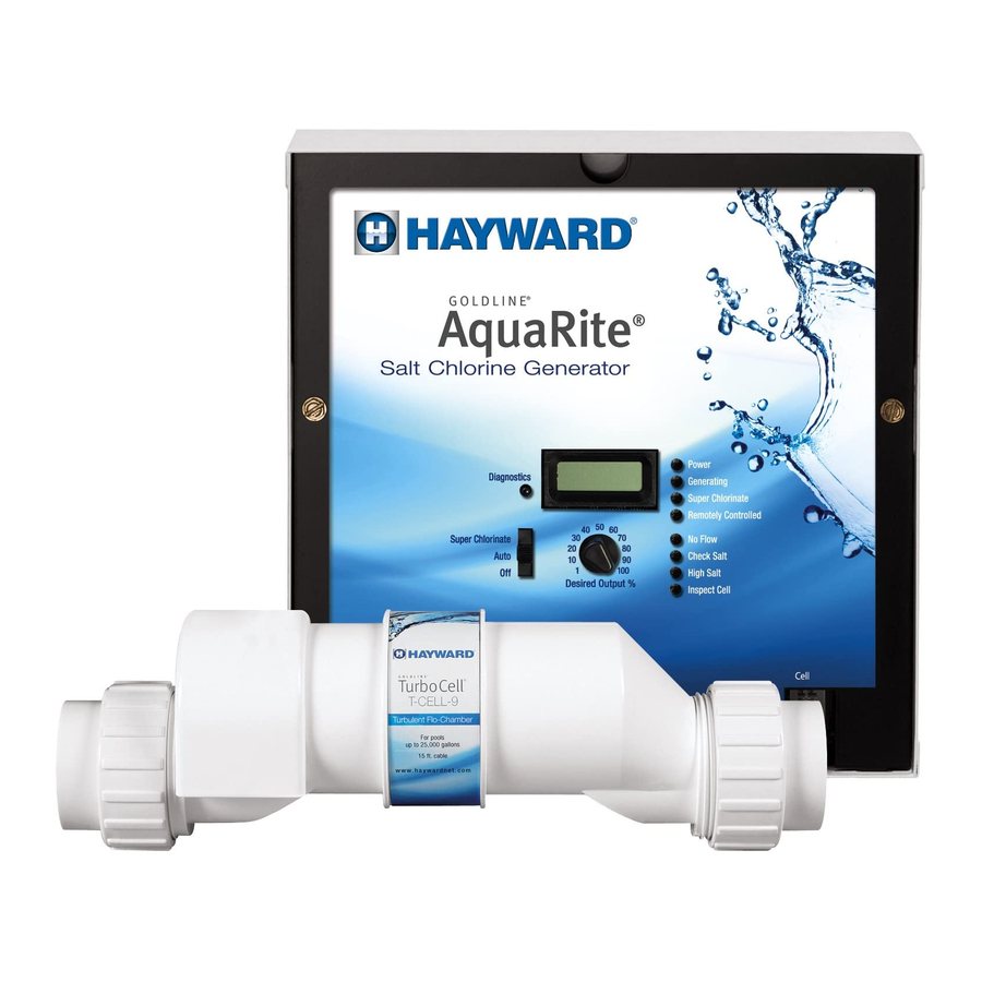
Hayward Aqua Rite® Operation And Installation Manual
Electronic chlorine generator
Hide thumbs
Also See for Aqua Rite®:
- Manual (20 pages) ,
- Operation and installation manual (10 pages) ,
- Installation manual (8 pages)
Summary of Contents for Hayward Aqua Rite®
- Page 1 Aqua Rite ® Electronic Chlorine Generator Operation and Installation Manual www.haywardnet.com...
- Page 2 IMPORTANT SAFETY INSTRUCTIONS When using this electrical equipment, basic safety precautions should always be followed, including the following: READ AND FOLLOW ALL • INSTRUCTIONS • Use Copper Conductors Only • Disconnect all AC power during installation. • Warning - To reduce the risk of injury, do not permit children to use this product unless they are closely supervised at all times.
-
Page 3: Table Of Contents
Table of Contents OPERATION General..................1 Water Chemistry................2 Controls..................6 Maintenance.................8 INSTALLATION Mounting..................10 Plumbing..................11 Wiring....................12 TROUBLESHOOTING Troubleshooting.................14 WARRANTY Warranty..................16... -
Page 4: Operation
NOTE: Hayward does not recommend using the Aqua Rite to generate bromine. Aqua Rite chlorine generators operating with software version 1.50 or later are designed to use one of 3 different chlorinator cells that are available from your authorized Hay- ward dealer. -
Page 5: Water Chemistry
Water Chemistry The table below summarizes the levels that are recommended by The Association of Pool and Spa Professionals (APSP). The only special requirements for the Aqua Rite are the salt level and stabilizer. It is important to maintain these levels in order to prevent corrosion or scaling and to ensure maximum enjoyment of the pool. - Page 6 Salt Level Use the chart on page 4 to determine how much salt in pounds or (Kgs) need to be added to reach the recommended levels. Use the equations below (measurements are in feet/ gallons and meters/liters) if pool size is unknown. Liters Gallons (pool size in meters)
-
Page 9: Controls
REMOTELY CONTROLLED When illuminated, indicates that a remote pool auto- mation control (Hayward/Goldline Pro Logic, Pentair Intellitouch, Polaris Eos, etc.) is controlling the Aqua Rite--the main switch and "Desired Output %" adjustment are inactive. When flashing, the Pro Logic, Intellitouch or Eos is in SERVICE or TIME-OUT mode and the Main Switch and "Desired Output %"... - Page 10 To Set Turbo Cell Type Before operation, the Aqua Rite must be configured for the chlorinator cell that will be used. Refer to the following information and steps below to set the Turbo cell type. "t-3" = T-CELL-3, GLX-CELL-3-W "t-5" = GLX-CELL-5, GLX-CELL-5-W "t-9 = T-CELL-9, GLX-CELL-9-W "t-15"...
-
Page 11: Maintenance
“Desired Output %” should be lowered accordingly. When connected to a pool automation control (Hayward/Goldline Pro Logic, Pentair Intellitouch or Polaris Eos): The Aqua Rite is designed to operate with all pool automation controls. The Pro Logic, Intellitouch or Eos can fully control the function of the Aqua Rite chlorinator in addition to the other pool equipment. - Page 12 The Aqua Rite electrolytic cell has a self cleaning feature incorporated into the elec- tronic control’s logic. In most cases this self cleaning action will keep the cell working at optimum efficiency. In areas where water is hard (high mineral content) and in pools where the water chemistry has been allowed to get "out of balance", the cell may require periodic cleaning.
-
Page 13: Installation
INSTALLATION Installation must be performed in accordance with Local and NEC codes. AQUA RITE Aqua Rite 120/240 VAC POWER LDLINE CONTROLS INC. FROM FROM POOL POOL Preparing Pool/Spa Water Refer to page 1 for recommended chemical levels. The pool's chemistry must be bal- ®... -
Page 14: Plumbing
Plumbing ® Ensure that the Aqua Rite installation does not constitute a cross connection with the local potable water supply. Consult local plumbing codes. The Aqua Rite is packaged with a flow switch and cell unions. The cell must be pur- chased separately. -
Page 15: Wiring
Wiring Power must be shut off at the circuit breaker before performing any wiring. Be sure to ® follow Local and NEC electrical codes. To provide safe operation, the Aqua Rite must be properly grounded and bonded. Input Power For stand alone operation: Wire the Aqua Rite to the LOAD SIDE of the filter pump timer. - Page 16 GROUND Optional Hayward/Goldline, Pentair and Polaris controls: The Hayward/Goldline, Pentair and Polaris controls use a 4 wire connection to commu- nicate to the Aqua Rite and can be wired up to 500' apart. Any outdoor rated 4 conductor cable can be used. Refer to each manufacturer's instructions and the wiring diagrams below for proper wiring connection to the Aqua Rite.
-
Page 17: Troubleshooting
Polaris - Attach wires to proper screw terminals as shown below. Note that screw terminal "1" is marked on the Polaris PCB. note marked black on PCB yellow Aqua Rite green TROUBLESHOOTING Visit www.goldlinecontrols.com for helpful information on operation, maintenance and ®... - Page 18 "Check Salt" LED illuminated or flashing Be sure that the correct model Turbo Cell has been selected (page 7). Check salt level in pool/spa. If salt level is low, add salt according to chart on page 4. Before adding large quantities of salt, it is advisable to have your salt level profession- ally checked.
-
Page 19: Warranty
SwimPure chlorination products to be free of defects in materials and workmanship, under normal use and service, for a period of three (3) years. Hayward/Goldline also warrants its Aqua Trol chlorination products to be free of defects in materials and workmanship, under normal use and service for a period of one (1) year. - Page 20 Electrolytic Cell inspect & clean Refer to section in manual. Head Loss Curve 12.03 6.79 3.08 40 (25%) 80 (50%) 120 (75%) 160 (100%) Flow Rate (gpm) 620 Division St. 092009N RevP Copyright © 2010 Hayward Inc. Elizabeth, NJ 07207...


Need help?
Do you have a question about the Aqua Rite® and is the answer not in the manual?
Questions and answers