Table of Contents
Advertisement
Quick Links
Download this manual
See also:
Use and Care Manual
Advertisement
Table of Contents

Related Manuals for Dacor DR30G


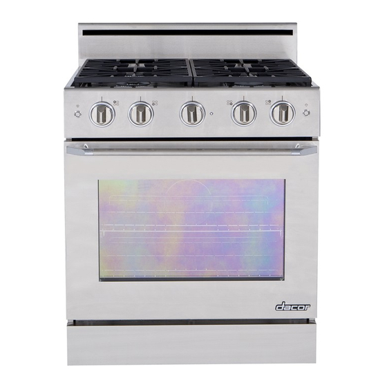
Summary of Contents for Dacor DR30G
-
Page 1: Installation Instructions
Installation Instructions Distinctive 30 - Inch Gas Range ™ For use with models DR30GS, DR30GFS, DR30GIS and DR30GIFS THIS APPLIANCE HAS BEEN TESTED IN ACCORDANCE WITH THE LATEST EDITION OF ANSI Z21.1a-2011 STANDARD FOR HOUSEHOLD GAS COOKING APPLIANCES. Part No. 105908 Rev. A... -
Page 2: Table Of Contents
No character = Equipped for low altitude operation Product data label (view through right side of grate with flashlight) All specifications subject to change without notice. Dacor assumes no liability for changes to specifications. © 2012 Dacor, all rights reserved. -
Page 3: Important Safety Instructions
Use common sense and caution when installing, maintaining or operating this appliance. WARNING Always contact the Dacor Customer Service Team about problems or conditions you do not understand. WARNING – NEVER cover any slots, holes or passages... -
Page 4: General Safety Precautions
Important Safety Instructions General Safety Precautions To reduce the risk of fire, explosion, electric shock, serious injury or death when installing or using this appliance, follow basic safety precautions, including the following: WARNING WARNING • Read the accompanying use and care manual •... - Page 5 Important Safety Instructions WARNING WARNING TO REDUCE THE RISK OF INJURY TO PERSONS IN • Do not expose the knobs to direct flame, hot utensils THE EVENT OF A RANGE TOP GREASE FIRE: or other sources of heat. a. SMOTHER FLAMES with a close-fitting lid, cookie •...
-
Page 6: Installation Specifications
1” above trim backguard* 3” (7.6 cm) backguard* DR30GI[F]S: 1 3/4” (4.4 cm) backguard* 1/4” (6.4 mm) See table for compatibility DR30G[F]S: External handle Full stainless 35” shown, some models steel side panels (88.9 cm) have integral handle (see inside cover) 37”... -
Page 7: Electrical Power Supply Requirements
Installation Specifications Gas Supply Requirements WARNING • Be certain that the range being installed is correct for • This appliance must be installed and electrically the gas service being provided (natural gas or LP gas). grounded in conformance to local codes. •... -
Page 8: Cabinet Layout
• To reduce the risk of personal injury and to reduce accumulated smoke in the room, Top of Note 1 Dacor strongly recommends installing finished a range hood. A range hood should counter project horizontally a minimum of five (5) Note 5 inches beyond the face of the cabinets. - Page 9 Installation Specifications Self-Rimming Installation Cutout Options (Models DR30GIS and DR30GIFS Only) For all self-rimming installations: Countertop height: 34 3/4” (88.3 cm) min. 36 7/8” (93.7 cm) max. Countertop thickness: 1 5/8” (4.1 cm) max. 10” min. (25.4 cm) 10” min. (25.4 cm) Rear wall or Non-combustible 3/4”...
-
Page 10: Gas And Electrical Locations
Existing utility connections may be used for replacement purposes, provided they meet local code • Dacor recommends that utility access for all models and fit within the utility clearance area at the back of be installed in an adjacent cabinet, as shown on page the range. - Page 11 Installation Instructions Four (4) plastic anchors are provided along with three sizes Attaching the bracket to a concrete floor: (4 each) of #8 or #12 Phillips head screws for attaching • Drill four (4) 3/8” diameter countersink holes through the anti-tip bracket to the floor. Use both the anchors and any existing floor covering to the concrete slab below.
-
Page 12: Backguard Kit Installation
Installation Instructions Installing the Anti-Tip Bracket on the Wall Top hole, indicates 1. Determine the suitability of wall mounting the anti-tip #12 x 1 3/4” bracket center line bracket. To use the wall mount option, the range front screw, panel must not be more than 27 3/8” (69.5 cm) from 4 places the wall and the bracket screws must be able to thread into the base plate inside the wall behind. -
Page 13: Adjust The Range Height
Installation Instructions Adjust the Range Height Door Removal 1. For stand alone configurations, raise the range until Remove the door to make the range easier to move during the top of the trim around the cooktop is at least the installation process. the same height as the countertop. -
Page 14: Gas Connection
Installation Instructions Gas Connection IMPORTANT: The installed gas pressure regulator is pre- set at the factory for the type of gas intended for use with the appliance. Verify that the appliance is compatible with WARNING the type of gas available by checking the product data label attached to the appliance. -
Page 15: Moving The Range To Final Location
Installation Instructions Moving the Range to Final Location Re-Installing the Door 1. Peel the protective plastic coating off of the range, WARNING including the range door. To avoid personal injury or damage to the door from it 2. Uncoil the power cord and route it to the electrical falling off its hinges: outlet so that it does not become trapped behind the range when it is pushed back. -
Page 16: Cooktop Assembly
Installation Instructions Cooktop Assembly WARNING Never attempt to operate the range’s cooktop with any of the burner rings, burner caps or grates removed. 1. Remove the burner rings, burner caps and grates from their shipping cartons. 2. Install the burners as shown. Gently twist each piece back and forth after installation to make sure it is properly seated. -
Page 17: Verifying Proper Operation
4. Test the left front burner on the cooktop 4. Repeat the above tests. by pushing in and turning the control knob 5. If the appliance still does not work, contact Dacor counterclockwise to the HIGH position. HIGH Distinctive Service at (800) 793-0093 ex. 2822. Do not The igniter for the left front burner will attempt to repair the appliance yourself. -
Page 18: Installation Checklist
Installation Instructions Installation Checklist WARNING To ensure a safe and proper installation, the installer must perform the following checklist to ensure that no part of the installation has been overlooked. Proper installation is the responsibility of the homeowner. □ Has the plastic coating been peeled off of the outside of the range? Have all packaging materials been removed from inside the oven? □... - Page 20 Dacor ● 14425 Clark Avenue, City of Industry, CA 91745 ● Phone: (800) 793-0093 ● Fax: (626) 403-3130 ● www.dacor.com...
Need help?
Do you have a question about the DR30G and is the answer not in the manual?
Questions and answers