D-Link DGS-3024 - Switch Manual
Managed 24-port gigabit ethernet switch
Hide thumbs
Also See for DGS-3024 - Switch:
- Manual (207 pages) ,
- User manual (145 pages) ,
- Command line interface reference manual (139 pages)
Table of Contents
Advertisement
Quick Links
Advertisement
Table of Contents

Related Manuals for D-Link DGS-3024 - Switch


Summary of Contents for D-Link DGS-3024 - Switch
- Page 1 D-Link ™ DGS-3024 Managed 24-Port Gigabit Ethernet Switch Manual...
- Page 2 © 2006 D-Link Corporation. All rights reserved. Reproduction in any manner whatsoever without the written permission of D-Link Corporation is strictly forbidden. Trademarks used in this text: D-Link and the D-Link logo are trademarks of D-Link Corporation; Microsoft and Windows are registered trademarks of Microsoft Corporation.
-
Page 3: Table Of Contents
DGS-3024 Gigabit Ethernet Switch Manual Table of Contents Preface ......................................ix Intended Readers..................................x Notes, Notices, and Cautions ..............................x Safety Instructions ..................................xi Introduction....................................... 1 Features......................................1 Ports ......................................1 Performance Features.................................. 1 Management....................................1 Unpacking and Setup ..................................3 Packing List .................................... - Page 4 DGS-3024 Gigabit Ethernet Switch Manual IP Address Assignment................................. 16 Connecting Devices to the Switch ..............................17 Web-Based Network Management..............................18 Introduction..................................... 18 Login to Web Manager .................................. 18 Web-based User Interface................................19 Areas of the User Interface ................................19 Configuration ....................................20 IP Address .......................................
- Page 5 DGS-3024 Gigabit Ethernet Switch Manual Unicast Forwarding ..................................51 Multicast Forwarding..................................51 Multicast Filtering..................................52 VLANs ......................................53 Understanding IEEE 802.1p Priority ............................53 VLAN Description..................................53 Notes About VLANs on the DGS-3024 ........................... 53 IEEE 802.1Q VLANs ................................54 802.1Q VLAN Tags..................................
- Page 6 DGS-3024 Gigabit Ethernet Switch Manual Security ......................................87 Trusted Host....................................87 Secure Socket Layer (SSL)................................88 Download Certificate..................................88 Configuration....................................89 Secure Shell (SSH) ..................................91 SSH Configuration..................................92 SSH Algorithm ..................................... 93 SSH User Authentication................................95 Access Authentication Control ..............................96 Policy and Parameters...................................
- Page 7 DGS-3024 Gigabit Ethernet Switch Manual Transmitted (TX) ..................................122 Errors......................................124 Received (RX) .................................... 124 Transmitted (TX) ..................................126 Size ......................................... 128 Switch History Log ..................................131 IGMP Snooping Group ................................132 IGMP Snooping Forwarding ............................... 133 VLAN Status ....................................133 Router Port....................................
- Page 8 DGS-3024 Gigabit Ethernet Switch Manual Glossary ......................................145 Warranty and Registration Information ............................ 148 Product Registration ..................................153 Tech Support....................................164 viii...
-
Page 9: Preface
DGS-3024 Gigabit Ethernet Switch Manual Preface The DGS-3024 Manual is divided into chapters that describe the system installation and operating instructions with examples. Section 1, “Introduction” – Describes the Switch and its features. Section 2, “Unpacking and Setup” – Helps you get started with the basic installation of the Switch.. Section 3, “Identifying External Components”... -
Page 10: Intended Readers
DGS-3024 Gigabit Ethernet Switch Manual Intended Readers The DGS-3024 Manual contains information for setup and management and of the DGS-3024 Switch. This guide is intended for network managers familiar with network management concepts and terminology. Notes, Notices, and Cautions NOTE: A NOTE indicates important information that helps you make better use of your device. -
Page 11: Safety Instructions
DGS-3024 Gigabit Ethernet Switch Manual Safety Instructions Use the following safety guidelines to ensure your own personal safety and to help protect your system from potential damage. Throughout this safety section, the caution icon ( ) is used to indicate cautions and precautions that you need to review and follow. - Page 12 DGS-3024 Gigabit Ethernet Switch Manual Safety Instructions (continued) • To help prevent an electric shock, plug the system and peripheral power cables into properly grounded electrical outlets. These cables are equipped with three-prong plugs to help ensure proper grounding. Do not use adapter plugs or remove the grounding prong from a cable.
- Page 13 DGS-3024 Gigabit Ethernet Switch Manual Safety Instructions (continued) Always load the rack from the bottom up, and load the heaviest item in the rack first. Make sure that the rack is level and stable before extending a component from the rack. Use caution when pressing the component rail release latches and sliding a component into or out of a rack;...
-
Page 14: Protecting Against Electrostatic Discharge
DGS-3024 Gigabit Ethernet Switch Manual Protecting Against Electrostatic Discharge Static electricity can harm delicate components inside your system. To prevent static damage, discharge static electricity from your body before you touch any of the electronic components, such as the microprocessor. You can do so by periodically touching an unpainted metal surface on the chassis. -
Page 15: Introduction
DGS-3024 Gigabit Ethernet Switch Manual NTRODUCTION This section describes the features of the DGS-3024. Features The DGS-3024 was designed for departmental and enterprise connections. As an all-gigabit-port Switch, it is ideal for backbone and server connection. Powerful and versatile, the Switch eliminates network bottlenecks while giving users the capability to fine- tune performance Switch features include: Ports... - Page 16 DGS-3024 Gigabit Ethernet Switch Manual • Built-in SNMP management: Bridge MIB (RFC 1493) MIB-II (RFC 1213) 802.1P/Q MIB (RFC 2674) Ethernet-like MIB (RFC 1643) Private MIB Mini-RMON MIB (RFC 1757) – four groups. The RMON specification defines the counters for the receive functions only.
-
Page 17: Unpacking And Setup
D-View 5.1 demo CD-ROM • This Manual with Registration Card on CD-ROM If any item is found missing or damaged, please contact your local D-Link reseller for replacement. Installation Use the following guidelines when choosing a place to install the Switch: •... -
Page 18: Desktop Or Shelf Installation
DGS-3024 Gigabit Ethernet Switch Manual Desktop or Shelf Installation When installing the Switch on a desktop or shelf, the rubber feet included with the device should first be attached. Attach these cushioning feet on the bottom at each corner of the device. Allow adequate space for ventilation between the device and the objects around it. -
Page 19: Power On
DGS-3024 Gigabit Ethernet Switch Manual Figure 2- 2B. Installing in an equipment rack Power on The Switch can be used with AC power supply 100-240 VAC, 50 - 60 Hz. The Switch’s power supply will adjust to the local power source automatically and may be powered on without having any or all LAN segment cables connected. After the Switch is plugged in, the LED indicators should respond as follows: •... -
Page 20: External Redundant Power System
DGS-3024 Gigabit Ethernet Switch Manual External Redundant Power System The Switch supports an external redundant power system. Figure 2-3. DPS-300 in DPS-900 case with DGS-3024 Figure 2-4. DPS-300 in DPS-800 case with DGS-3024 NOTE: See the DPS-300 documentation for more information. CAUTION: Do not use the Switch with any redundant power system other than the DPS-300. -
Page 21: Identifying External Components
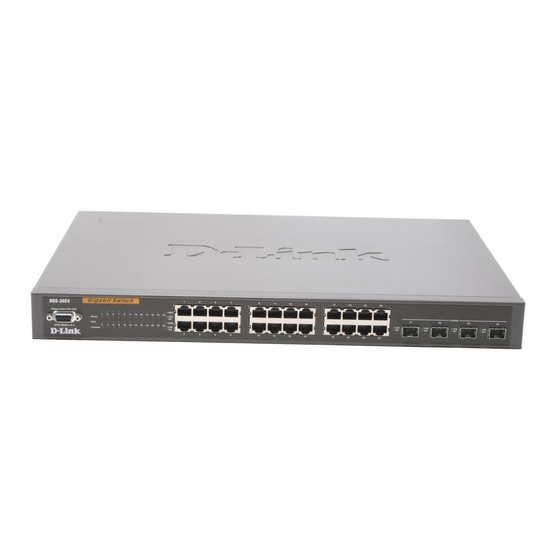
DGS-3024 Gigabit Ethernet Switch Manual DENTIFYING XTERNAL OMPONENTS This chapter describes the front panel, rear panel, side panels, and LED indicators of the DGS-3024. Front Panel The front panel of the Switch consists of LED indicators, an RS-232 communication port, 24 1000BASE-T ports, and four mini- GBIC combo ports. -
Page 22: Side Panels
DGS-3024 Gigabit Ethernet Switch Manual Side Panels The right side panel of the Switch contains two system fans (see the top part of the diagram below). The left side panel contains heat vents. Figure 3-3. Side panel views of the Switch The system fans are used to dissipate heat. -
Page 23: Connecting The Switch
DGS-3024 Gigabit Ethernet Switch Manual ONNECTING THE WITCH This chapter describes how to connect the DGS-3024 to your Gigabit Ethernet network. Switch to End Node End nodes include PCs outfitted with a 10, 100, or 1000 Mbps RJ-45 Ethernet/Fast Ethernet/Gigabit Ethernet Network Interface Card (NIC) and most routers. -
Page 24: Switch To Hub Or Switch
DGS-3024 Gigabit Ethernet Switch Manual Switch to Hub or Switch These connections can be accomplished in a number of ways using a normal cable. • A 10BASE-T hub or Switch can be connected to the Switch via a two-pair Category 3, 4, 5, or 5e UTP/STP cable. •... -
Page 25: Introduction To Switch Management
DGS-3024 Gigabit Ethernet Switch Manual NTRODUCTION TO WITCH ANAGEMENT Management Options This system may be managed out-of-band through the console port on the front panel or in-band using Telnet. The user may also choose the web-based management, accessible through a web browser. Web-based Management Interface After you have successfully installed the Switch, you can configure the Switch, monitor the LED panel, and display statistics graphically using a web browser, such as Netscape Navigator (version 6.2 and higher) or Microsoft®... - Page 26 DGS-3024 Gigabit Ethernet Switch Manual NOTE: When you use HyperTerminal with the Microsoft® Windows® 2000 operating system, ensure that you have Windows 2000 Service Pack 2 or later installed. Windows 2000 Service Pack 2 allows you to use arrow keys in HyperTerminal's VT100 emulation. See www.microsoft.com for information on Windows 2000 service packs.
-
Page 27: First Time Connecting To The Switch
DGS-3024 Gigabit Ethernet Switch Manual First Time Connecting to The Switch The Switch supports user-based security that can allow you to prevent unauthorized users from accessing the Switch or changing its settings. This section tells how to log onto the Switch. NOTE: The passwords used to access the Switch are case-sensitive;... -
Page 28: Password Protection
DGS-3024 Gigabit Ethernet Switch Manual Password Protection The DGS-3024 does not have a default user name and password. One of the first tasks when settings up the Switch is to create user accounts. If you log in using a predefined administrator-level user name, you have privileged access to the Switch's management software. -
Page 29: Snmp Settings
DGS-3024 Gigabit Ethernet Switch Manual SNMP Settings Simple Network Management Protocol (SNMP) is an OSI Layer 7 (Application Layer) designed specifically for managing and monitoring network devices. SNMP enables network management stations to read and modify the settings of gateways, routers, Switches, and other network devices. -
Page 30: Ip Address Assignment
DGS-3024 Gigabit Ethernet Switch Manual IP Address Assignment Each Switch must be assigned its own IP Address, which is used for communication with an SNMP network manager or other TCP/IP application (for example BOOTP, TFTP). The Switch's default IP address is 10.90.90.90. You can change the default Switch IP address to meet the specification of your networking address scheme. -
Page 31: Connecting Devices To The Switch
DGS-3024 Gigabit Ethernet Switch Manual Figure 5- 4. Assigning the Switch an IP Address In the above example, the Switch was assigned an IP address of 10.53.13.224 with a subnet mask of 255.0.0.0. The system message Success indicates that the command was executed successfully. Please remember to save your new settings before you logout or they will be lost. -
Page 32: Web-Based Network Management
DGS-3024 Gigabit Ethernet Switch Manual ASED ETWORK ANAGEMENT Introduction The DGS-3024 offers an embedded Web-based (HTML) interface allowing users to manage the Switch from anywhere on the network through a standard browser, such as Opera, Netscape Navigator/Communicator, or Microsoft Internet Explorer. The Web browser acts as a universal access tool and can communicate directly with the Switch using the HTTP protocol. -
Page 33: Web-Based User Interface
DGS-3024 Gigabit Ethernet Switch Manual Leave both the User Name field and the Password field blank and click OK. This will open the Web-based user interface. The Switch management features available in the Web-based manager are explained below. Web-based User Interface The user interface provides access to various Switch configuration and management windows, allows you to view performance statistics, and permits you to graphically monitor the system status. -
Page 34: Configuration
DGS-3024 Gigabit Ethernet Switch Manual ONFIGURATION The first Web Manager main folder is Configuration and includes the following windows and sub-folders: IP Address, Switch Information, Advanced Settings, Port Configuration, Port Mirroring, Trunking, IGMP Snooping, Spanning Tree, Forwarding & Filtering, VLANs, SNTP Settings, QoS, MAC Notification, System Log Server, Port Access Entity, and Static ARP Settings, as well as secondary windows. - Page 35 DGS-3024 Gigabit Ethernet Switch Manual Use the Get IP From pull-down menu to choose from BOOTP or DHCP. This selects how the Switch will be assigned an IP address on the next reboot. The IP Address Settings options are: Parameter Description The Switch will send out a BOOTP broadcast request when it is powered up.
- Page 36 DGS-3024 Gigabit Ethernet Switch Manual...
-
Page 37: Switch Information
DGS-3024 Gigabit Ethernet Switch Manual Switch Information This window is used to enter name, location, and contact information. Click Apply to activate the new settings. Figure 7- 2. Switch Information (Basic Settings) window The information is described as follows: Parameter Description Device Type A description of the Switch type. -
Page 38: Advanced Settings
DGS-3024 Gigabit Ethernet Switch Manual Advanced Settings The Switch Information (Advanced Settings) window contains the main settings for all major functions for the Switch. To view this window, click its link in the Configuration folder. This will enable the following window to be viewed and configured. Figure 7- 3. - Page 39 DGS-3024 Gigabit Ethernet Switch Manual This indicates if a Telnet connection is currently enabled on the Switch. The default is Enabled. Telnet Status Telnet TCP Port The TCP port number. TCP ports are numbered between 1 and 65535. The "well-known" TCP port for the Telnet protocol is 23.
-
Page 40: Port Configuration
DGS-3024 Gigabit Ethernet Switch Manual Port Configuration This section contains information for configuring various attributes and properties for individual physical ports, including port speed and flow control. Clicking Configuration > Port Configurations > Port Settings in the menu will display the following window for the user: Figure 7- 4. - Page 41 DGS-3024 Gigabit Ethernet Switch Manual Parameter Description State Toggle the State field to either enable or disable a given port or group of ports. Speed/Duplex Toggle the Speed/Duplex field to either select the speed and duplex/half-duplex state of the port. Auto denotes auto-negotiation between 10 and 100 Mbps devices, in full- or half-duplex.
-
Page 42: Port Description
DGS-3024 Gigabit Ethernet Switch Manual Port Description The DGS-3024 supports a port description feature where the user may name various ports on the Switch. To assign names to various ports, click the Port Description in the Port Configuration folder of the Configuration menu. Use the From and To pull-down menu to choose a port or range of ports to describe, and then enter a description of the port(s). -
Page 43: Port Mirroring
DGS-3024 Gigabit Ethernet Switch Manual Port Mirroring The Switch allows the user to copy frames transmitted and received on a port and redirect the copies to another port. The user can attach a monitoring device to the mirrored port, such as a sniffer or an RMON probe, to view details about the packets passing through the first port. -
Page 44: Link Aggregation (Port Trunking)
DGS-3024 Gigabit Ethernet Switch Manual Link Aggregation (Port Trunking) Port trunk groups are used to combine a number of ports together to make a single high-bandwidth data pipeline. NOTE: Static Type Link Aggregation is usually referred as “Port Trunking.” In this section, the terms “Link Aggregation” and “Port Trunking” will be used synonymously. - Page 45 DGS-3024 Gigabit Ethernet Switch Manual NOTE: If any ports within the trunk group become disconnected, packets intended for the disconnected port will be load shared among the other uplinked ports of the port trunking group. Port trunking allows several ports to be grouped together and to act as a single link. This gives a bandwidth that is a multiple of a single link's bandwidth.
- Page 46 DGS-3024 Gigabit Ethernet Switch Manual Figure 7- 9. Port Trunking Configuration window The user-changeable parameters are as follows: Parameter Description Select an ID number for the group, between 1 and 4. Group ID [1-4] Trunk groups can be toggled between Enabled and Disabled. This is used to turn a port trunking State group on or off.
-
Page 47: Lacp Port Settings
DGS-3024 Gigabit Ethernet Switch Manual LACP Port Settings The LACP Port Settings window is used in conjunction with the Link Aggregation window to create port trunking groups on the Switch. Using the following window, the user may set which ports will be active and passive in processing and sending LACP control frames. -
Page 48: Igmp Snooping
DGS-3024 Gigabit Ethernet Switch Manual IGMP Snooping Internet Group Management Protocol (IGMP) snooping allows the Switch to recognize IGMP queries and reports sent between network stations or devices and an IGMP host. When enabled for IGMP snooping, the Switch can open or close a port to a specific device based on IGMP messages passing through the Switch. - Page 49 DGS-3024 Gigabit Ethernet Switch Manual Parameter Description This is the VLAN ID that, along with the VLAN Name, identifies the VLAN for which to modify VLAN ID the IGMP Snooping Settings. This is the VLAN Name that, along with the VLAN ID, identifies the VLAN for which to modify VLAN Name the IGMP Snooping Settings.
-
Page 50: Static Router Ports Entry
DGS-3024 Gigabit Ethernet Switch Manual Static Router Ports Entry A static router port is a port that has a multicast router attached to it. Generally, this router would have a connection to a WAN or to the Internet. Establishing a router port will allow multicast packets coming from the router to be propagated through the network, as well as allowing multicast messages (IGMP) coming from the network to be propagated to the router. -
Page 51: Spanning Tree
STP will be familiar to most networking professionals. However, since 802.1w RSTP and 802.1s MSTP has been recently introduced to D-Link managed Ethernet Switches, a brief introduction to the technology is provided below followed by a description of how to set up 802.1d STP, 802.1w RSTP and 802.1s MSTP. -
Page 52: Port Transition States
DGS-3024 Gigabit Ethernet Switch Manual Port Transition States An essential difference between the three protocols is in the way ports transition to a forwarding state and in the way this transition relates to the role of the port (forwarding or not forwarding) in the topology. MSTP and RSTP combine the transition states disabled, blocking and listening used in 802.1d and creates a single state Discarding. -
Page 53: Stp Loopback Detection
DGS-3024 Gigabit Ethernet Switch Manual STP Loopback Detection When connected to other switches, STP is an important configuration in consistency for delivering packets to ports and can greatly improve the throughput of your switch. Yet, even this function can malfunction with the emergence of STP BPDU packets that occasionally loop back to the Switch, such as BPDU packets looped back from an unmanaged switch connected to the DGS- 3024. -
Page 54: Stp Bridge Global Settings
DGS-3024 Gigabit Ethernet Switch Manual STP Bridge Global Settings To open the following window, open the Spanning Tree folder in the Configuration menu and click the STP Bridge Global Settings link. Figure 7- 15. STP Bridge Global Settings window – STP compatible Figure 7- 16. - Page 55 DGS-3024 Gigabit Ethernet Switch Manual The following parameters can be set: Parameter Description Use the pull-down menu to enable or disable STP globally on the Switch. The default is Disabled. STP Status Use the pull-down menu to choose the desired version of STP to be implemented on the Switch. STP Version There are three choices: STP - Select this parameter to set the Spanning Tree Protocol (STP) globally on the Switch.
-
Page 56: Mst Configuration Table
DGS-3024 Gigabit Ethernet Switch Manual MST Configuration Table The following windows allow the user to configure a MSTI instance on the Switch. These settings will uniquely identify a multiple spanning tree instance set on the Switch. The Switch initially possesses one CIST or Common Internal Spanning Tree of which the user may modify the parameters for but cannot change the MSTI ID for, and cannot be deleted. - Page 57 DGS-3024 Gigabit Ethernet Switch Manual Figure 7- 19. Instance ID Settings window - Add The user may configure the following parameters to create a MSTI in the Switch. Parameter Description MSTI ID Enter a number between 1 and 15 to set a new MSTI on the Switch. Type Create is selected to create a new MSTI.
- Page 58 DGS-3024 Gigabit Ethernet Switch Manual To configure the parameters for a previously set MSTI, click on its hyperlinked MSTI ID number, which will reveal the following window for configuration. Figure 7- 21. Instance ID Settings window - Modify The user may configure the following parameters for a MSTI on the Switch. Parameter Description MSTI ID...
-
Page 59: Msti Settings
DGS-3024 Gigabit Ethernet Switch Manual MSTI Settings This window displays the current MSTI configuration settings and can be used to update the port configuration for an MSTI ID. If a loop occurs, the MSTP function will use the port priority to select an interface to put into the forwarding state. Set a higher priority value for interfaces to be selected for forwarding first. -
Page 60: Stp Instance Settings
DGS-3024 Gigabit Ethernet Switch Manual STP Instance Settings The following window displays MSTIs currently set on the Switch. To view the following table, click Configuration > Spanning Tree > STP Instance Settings: Figure 7- 24. STP Instance Settings window The following information is displayed: Parameter Description Instance Type... - Page 61 DGS-3024 Gigabit Ethernet Switch Manual Figure 7- 26. STP Instance Operational Status window – Previously Configured MSTI The following parameters may be viewed in the STP Instance Operational Status windows: Parameter Description This field will show the priority and MAC address of the Root Bridge. Designated Root Bridge This defines a metric that indicates the relative cost of forwarding packets to the specified External Root Cost...
- Page 62 DGS-3024 Gigabit Ethernet Switch Manual The Forward Delay can be from 4 to 30 seconds. Any port on the Switch spends this time Forward Delay in the listening state while moving from the blocking state to the forwarding state. Last Topology Change This field shows the time, in seconds, since the last spanning tree topology change.
-
Page 63: Stp Port Settings
DGS-3024 Gigabit Ethernet Switch Manual STP Port Settings STP can be set up on a port per port basis. To view the following window click Configuration > Spanning Tree > STP Port Settings: Figure 7- 27. STP Port Settings window In addition to setting Spanning Tree parameters for use on the Switch level, the Switch allows for the configuration of groups of ports, each port-group of which will have its own spanning tree, and will require some of its own configuration settings. - Page 64 DGS-3024 Gigabit Ethernet Switch Manual Parameter Description From/To A consecutive group of ports may be configured starting with the selected port. External Cost (0 This defines a metric that indicates the relative cost of forwarding packets to the specified port = Auto) list.
-
Page 65: Forwarding & Filtering
DGS-3024 Gigabit Ethernet Switch Manual Forwarding & Filtering Unicast Forwarding Open the Forwarding folder in the Configuration menu and click on the Unicast Forwarding link. This will open the Setup Static Unicast Forwarding Table window, as shown below: Figure 7- 28. Setup Static Unicast Forwarding Table window To add or edit an entry, define the following parameters and then click Add/Modify: Parameter Description... -
Page 66: Multicast Filtering
DGS-3024 Gigabit Ethernet Switch Manual Figure 7- 30. Setup Static Multicast Forwarding Table window The following parameters can be set: Parameter Description The VLAN ID of the VLAN the corresponding MAC address belongs to. Multicast MAC The MAC address of the static source of multicast packets. This must be a multicast MAC address. -
Page 67: Vlans
DGS-3024 Gigabit Ethernet Switch Manual VLANs Understanding IEEE 802.1p Priority Priority tagging is a function defined by the IEEE 802.1p standard designed to provide a means of managing traffic on a network where many different types of data may be transmitted simultaneously. It is intended to alleviate problems associated with the delivery of time critical data over congested networks. -
Page 68: Ieee 802.1Q Vlans
DGS-3024 Gigabit Ethernet Switch Manual IEEE 802.1Q VLANs Some relevant terms: Tagging – The act of putting 802.1Q VLAN information into the header of a packet. Untagging – The act of stripping 802.1Q VLAN information out of the packet header. Ingress port –... -
Page 69: 802.1Q Vlan Tags
DGS-3024 Gigabit Ethernet Switch Manual 802.1Q VLAN Tags The figure below shows the 802.1Q VLAN tag. There are four additional octets inserted after the source MAC address. Their presence is indicated by a value of 0x8100 in the EtherType field. When a packet's EtherType field is equal to 0x8100, the packet carries the IEEE 802.1Q/802.1p tag. -
Page 70: Port Vlan Id
DGS-3024 Gigabit Ethernet Switch Manual Port VLAN ID Packets that are tagged (are carrying the 802.1Q VID information) can be transmitted from one 802.1Q compliant network device to another with the VLAN information intact. This allows 802.1Q VLANs to span network devices (and indeed, the entire network, if all network devices are 802.1Q compliant). -
Page 71: Default Vlans
DGS-3024 Gigabit Ethernet Switch Manual ingress port. If it does not, the packet is dropped. If it has the same VID, the packet is forwarded and the destination port transmits it on its attached network segment. This process is referred to as ingress filtering and is used to conserve bandwidth within the Switch by dropping packets that are not on the same VLAN as the ingress port at the point of reception. -
Page 72: Static Vlan Entry
DGS-3024 Gigabit Ethernet Switch Manual Static VLAN Entry In the Configuration folder, open the VLANs folder and click the Static VLAN Entry link to open the following window: Figure 7- 35. 802.1Q Static VLANs window The first 802.1Q Static VLANs window lists all previously configured VLANs by VLAN ID and VLAN Name. To delete an existing 802.1Q VLAN, click the corresponding button under the Delete heading. - Page 73 DGS-3024 Gigabit Ethernet Switch Manual Figure 7- 37. 802.1Q Static VLANs window (Modify) The following fields can then be set in either the Add or Modify 802.1Q Static VLANs windows: Parameter Description VID (VLAN ID) Allows the entry of a VLAN ID in the Add window, or displays the VLAN ID of an existing VLAN in the Modify window.
-
Page 74: Q Port Settings
DGS-3024 Gigabit Ethernet Switch Manual 802.1Q Port Settings In the Configuration menu, open the VLANs folder and click 802.1Q Port Settings. This GVRP Settings window (shown below), allows you to determine whether the Switch will share its VLAN configuration information with other GARP VLAN Registration Protocol (GVRP) enabled Switches. -
Page 75: Sntp Settings
DGS-3024 Gigabit Ethernet Switch Manual SNTP Settings Time Setting To configure the time settings for the Switch, open the Configuration folder, then the SNTP Settings folder and click on the Time Setting link, revealing the following window for the user to config- ure. -
Page 76: Time Zone And Dst
DGS-3024 Gigabit Ethernet Switch Manual Time Zone and DST The following are windows used to configure time zones and Daylight Savings time settings for SNTP. Open the Configuration folder, then the SNTP Setting folder and click on the Time Zone and DST link, revealing the following window. Figure 7- 40. - Page 77 DGS-3024 Gigabit Ethernet Switch Manual DST Repeating Settings - Using repeating mode will enable DST seasonal time adjustment. Repeating mode requires that the DST beginning and ending date be specified using a formula. For example, specify to begin DST on Saturday during the second week of April and end DST on Sunday during the last week of October.
-
Page 78: Qos
DGS-3024 Gigabit Ethernet Switch Manual The DGS-3024 supports 802.1p priority queuing Quality of Service. The following section discusses the implementation of QoS (Quality of Service) and benefits of using 802.1p priority queuing. Advantages of QoS QoS is an implementation of the IEEE 802.1p standard that allows network administrators a method of reserving bandwidth for important functions that require a large bandwidth or have a high priority, such as VoIP (voice-over Internet Protocol), Web browsing applications, file server applications or video conferencing. -
Page 79: Understanding Qos
DGS-3024 Gigabit Ethernet Switch Manual Understanding QoS The Switch has four priority queues. These priority queues are labeled as 3, the highest queue to 0, the lowest queue. The eight priority tags, specified in IEEE 802.1p are mapped to the Switch's priority tags as follows: Priority 0 is assigned to the Switch's Q1 queue. -
Page 80: Port Bandwidth
DGS-3024 Gigabit Ethernet Switch Manual Port Bandwidth The bandwidth control settings are used to place a ceiling on the transmitting and receiving data rates for any selected port. In the Configuration folder, click QoS > Port Bandwidth, to view the window shown below. -
Page 81: Traffic Control
DGS-3024 Gigabit Ethernet Switch Manual Traffic Control Use the Traffic Control window to enable or disable storm control and adjust the threshold for multicast/broadcast/DLF (Destination Look Up Failure) storms. Traffic control settings are applied to individual Switch modules. To view the following window, click Configuration >... -
Page 82: 802.1P Default Priority
DGS-3024 Gigabit Ethernet Switch Manual 802.1p Default Priority The Switch allows the assignment of a default 802.1p priority to each port on the Switch. In the Configuration folder open the QoS folder and click 802.1p Default Priority, to view the window shown below. Figure 7- 44. -
Page 83: 802.1P User Priority
DGS-3024 Gigabit Ethernet Switch Manual 802.1p User Priority The DGS-3024 allows the assignment of a user priority to each of the 802.1p priorities. In the Configuration folder open the QoS folder and click 802.1p User Priority, to view the window shown below. Figure 7- 45. -
Page 84: Qos Output Scheduling
DGS-3024 Gigabit Ethernet Switch Manual The Scheduling Mechanism has the following parameters. Parameter Description Strict The highest class of service is the first to process traffic. That is, the highest class of service will finish before other queues empty. RoundRobin Use the weighted round-robin (WRR) algorithm to handle packets in an even distribution in priority classes of service. -
Page 85: Mac Notification
DGS-3024 Gigabit Ethernet Switch Manual MAC Notification MAC Notification is used to monitor MAC addresses learned and entered into the forwarding database. MAC Notification Global Settings To globally set MAC notification on the Switch, open the following window by opening the MAC Notification folder and clicking the MAC Notification Global Settings link: Figure 7- 48. -
Page 86: Mac Notification Port Settings
DGS-3024 Gigabit Ethernet Switch Manual MAC Notification Port Settings To change MAC notification settings for a port or group of ports on the Switch, click MAC Notification Port Settings in the MAC Notification folder, which will display the following window: Figure 7- 49. -
Page 87: System Log Server
DGS-3024 Gigabit Ethernet Switch Manual System Log Server The Switch can send Syslog messages to up to four designated servers using the System Log Server. In the Configuration folder, click System Log Server, to view the window shown below. Figure 7- 50. System Log Servers window The parameters configured for adding and editing System Log Server settings are the same. - Page 88 DGS-3024 Gigabit Ethernet Switch Manual Code kernel messages user-level messages mail system system daemons security/authorization messages messages generated internally by Syslog line printer subsystem network news subsystem UUCP subsystem clock daemon security/authorization messages FTP daemon NTP subsystem log audit log alert clock daemon local use 0 (local0) local use 1 (local1)
-
Page 89: Port Access Entity
DGS-3024 Gigabit Ethernet Switch Manual Port Access Entity 802.1x Port-Based Access Control The IEEE 802.1x standard is a security measure for authorizing and authenticating users to gain access to various wired or wireless devices on a specified Local Area Network by using a Client and Server based access control model. This is accomplished by using a RADIUS server to authenticate users trying to access a network by relaying Extensible Authentication Protocol over LAN (EAPOL) packets between the Client and the Server. -
Page 90: Authentication Server
DGS-3024 Gigabit Ethernet Switch Manual Authentication Server The Authentication Server is a remote device that is connected to the same network as the Client and Authenticator, must be running a RADIUS Server program and must be configured properly on the Authenticator (Switch). Clients connected to a port on the Switch must be authenticated by the Authentication Server (RADIUS) before attaining any services offered by the Switch on the LAN. -
Page 91: Client
DGS-3024 Gigabit Ethernet Switch Manual Figure 7- 55. Authenticator Client The Client is simply the workstation that wishes to gain access to the LAN or Switch services. All workstation must be running software that is compliant with the 802.1x protocol. For users running Windows XP, the software is included within the operating system. -
Page 92: Port-Based Network Access Control
DGS-3024 Gigabit Ethernet Switch Manual Port-Based Network Access Control The original intent behind the development of 802.1x was to leverage the characteristics of point-to-point in LANs. Any single LAN segment in such an infrastructures has no more than two devices attached to it, one of which is a Bridge Port. The Bridge Port detects events that indicate the attachment of an active device at the remote end of the link, or an active device becoming inactive. -
Page 93: Configure Authenticator
DGS-3024 Gigabit Ethernet Switch Manual Configure Authenticator To configure the 802.1x Authenticator Settings, click Configure Authenticator: Figure 7- 58. First 802.1x Authenticator Settings window To configure the settings by port, click on the hyperlinked port number under the Port heading, which will display the following table to configure:... - Page 94 DGS-3024 Gigabit Ethernet Switch Manual Figure 7- 59. 802.1x Authenticator Settings window - Modify This window allows the following features to be set: Parameter Description From and To Enter the port or ports to be set. AdmDir Sets the administrative-controlled direction to either in or both. If in is selected, control is only exerted over incoming traffic through the port you selected in •...
-
Page 95: Local Users
DGS-3024 Gigabit Ethernet Switch Manual This value determines timeout conditions in the exchanges between the Authenticator and the ServerTimeout authentication server. The default setting is 30 seconds. MaxReq The maximum number of times that the Switch will retransmit an EAP Request to the client before it times out of the authentication sessions. -
Page 96: 802.1X Capability Settings
DGS-3024 Gigabit Ethernet Switch Manual 802.1x Capability Settings Click 802.1x Capability Settings to view the following window: Figure 7- 61. 802.1x Capability Settings window To set up the Switch's 802.1x port-based authentication, select which ports are to be configured in the From and To fields. Next, enable the ports by selecting Authenticator from the drop-down menu under Capability. -
Page 97: Initialize Port(S)
DGS-3024 Gigabit Ethernet Switch Manual Initialize Port(s) To initialize ports for the port-based side of 802.1x, the user must first enable 802.1x by Port Base under Switch 802.1x in the Switch Information (Advanced Settings) window. Existing 802.1x port and MAC settings are displayed and can be configured using the window below. Click Initialize Port(s) to open the following window: Figure 7- 62. -
Page 98: Reauthenticate Port(S)
DGS-3024 Gigabit Ethernet Switch Manual Reauthenticate Port(s) This window allows you to reauthenticate a port or group of ports by choosing a port or group of ports by using the pull down menus From and To and clicking Apply. The Reauthenticate Port Table displays the current status of the reauthenticated port(s) once you have clicked Apply. -
Page 99: Radius Server
DGS-3024 Gigabit Ethernet Switch Manual RADIUS Server The RADIUS feature of the Switch allows you to facilitate centralized user administration as well as providing protection against a sniffing, active hacker. Click Port Access Entity > RADIUS Server to open the Authentic RADIUS Server Setting window shown below: Figure 7- 64. -
Page 100: Static Arp Settings
DGS-3024 Gigabit Ethernet Switch Manual Static ARP Settings The Address Resolution Protocol (ARP) is a TCP/IP protocol that converts IP addresses into physical addresses. This table allows network managers to view, define, modify and delete ARP information for specific devices. Static entries can be defined in the ARP Table. -
Page 101: Security
DGS-3024 Gigabit Ethernet Switch Manual ECURITY The second Web Manager main folder is Security and includes the following windows and sub-folders: Trusted Host, Secure Socket Layer (SSL), Secure Shell (SSH), and Access Authentication Control, as well as secondary windows. Trusted Host Go to the Security folder and click on the Trusted Host link;... -
Page 102: Secure Socket Layer (Ssl)
DGS-3024 Gigabit Ethernet Switch Manual Secure Socket Layer (SSL) Secure Sockets Layer or SSL is a security feature that will provide a secure communication path between a host and client through the use of authentication, digital signatures and encryption. These security functions are implemented through the use of a ciphersuite, which is a security string that determines the exact cryptographic parameters, specific encryption algorithms and key sizes to be used for an authentication session and consists of three levels: 1. -
Page 103: Configuration
DGS-3024 Gigabit Ethernet Switch Manual To download certificates, set the following parameters and click Apply. Parameter Description Server IP Enter the IP address of the TFTP server where the certificate files are located. Certificate File Name Enter the path and the filename of the certificate file to download. This file must have a .der extension. - Page 104 DGS-3024 Gigabit Ethernet Switch Manual This ciphersuite combines the DSA Diffie Hellman key exchange, CBC Block Cipher DHS DSS with 3DES 3DES_EDE encryption and SHA Hash Algorithm. Use the pull-down menu to enable or EDE CBC SHA disable this ciphersuite. This field is Enabled by default. RSA EXPORT with This ciphersuite combines the RSA Export key exchange and stream cipher RC4 encryption RC4 40 MD5...
-
Page 105: Secure Shell (Ssh)
DGS-3024 Gigabit Ethernet Switch Manual Secure Shell (SSH) SSH is an abbreviation of Secure Shell, which is a program allowing secure remote login and secure network services over an insecure network. It allows a secure login to remote host computers, a safe method of executing commands on a remote end node, and will provide secure encrypted and authenticated communication between two non-trusted hosts. -
Page 106: Ssh Configuration
DGS-3024 Gigabit Ethernet Switch Manual SSH Configuration The following window is used to configure and view settings for the SSH server and can be opened by clicking Security > Secure Shell (SSH) > SSH Configuration: Figure 8- 4. Current SSH Configuration Settings window To configure the SSH server on the Switch, modify the following parameters and click Apply: Parameter Description... -
Page 107: Ssh Algorithm
DGS-3024 Gigabit Ethernet Switch Manual SSH Algorithm This window allows the configuration of the desired types of SSH algorithms used for authentication encryption. There are three categories of algorithms listed and specific algorithms of each may be enabled or disabled by using their corresponding pull-down menus. - Page 108 DGS-3024 Gigabit Ethernet Switch Manual Use the pull-down to enable or disable the Advanced Encryption Standard AES-256 AES256-CBC encryption algorithm with Cipher Block Chaining. The default is Enabled. ARC4 Use the pull-down to enable or disable the Arcfour encryption algorithm with Cipher Block Chaining.
-
Page 109: Ssh User Authentication
DGS-3024 Gigabit Ethernet Switch Manual SSH User Authentication The following windows are used to configure parameters for users attempting to access the Switch through SSH. To access the following window, click Security Management > Secure Shell > SSH User Authentication Mode. Figure 8- 6. -
Page 110: Access Authentication Control
DGS-3024 Gigabit Ethernet Switch Manual Access Authentication Control The TACACS / XTACACS / TACACS+ / RADIUS commands let you secure access to the Switch using the TACACS / XTACACS / TACACS+ / RADIUS protocols. When a user logs in to the Switch or tries to access the administrator level privilege, he or she is prompted for a password. -
Page 111: Policy And Parameters
DGS-3024 Gigabit Ethernet Switch Manual Policy and Parameters This feature will enable an administrator-defined authentication policy for users trying to access the Switch. When enabled, the device will check the Login Method List and choose a technique for user authentication upon login. To access the following window, click Security >... -
Page 112: Authentication Server Group
DGS-3024 Gigabit Ethernet Switch Manual Parameter Description Application Lists the configuration applications on the Switch. The user may configure the Login Method List and Enable Method List for authentication for users utilizing the Console (Command Line Interface) application, the Telnet application, SSH and the Web (HTTP) application. Using the pull down menu, configure an application for normal login on the user level, utilizing Login Method List a previously configured method list. - Page 113 DGS-3024 Gigabit Ethernet Switch Manual Figure 8- 11. Add a Server Host to Server Group (XTACACS) window. To add an Authentication Server Host to the list, enter its IP address in the IP Address field, choose the protocol associated with the IP address of the Authentication Server Host and click Add to add this Authentication Server Host to the group.
-
Page 114: Authentication Server Host
DGS-3024 Gigabit Ethernet Switch Manual Authentication Server Host This window will set user-defined Authentication Server Hosts for the TACACS / XTACACS / TACACS+ / RADIUS security protocols on the Switch. When a user attempts to access the Switch with Authentication Policy enabled, the Switch will send authentication packets to a remote TACACS / XTACACS / TACACS+ / RADIUS server host on a remote host. -
Page 115: Login Method Lists
DGS-3024 Gigabit Ethernet Switch Manual Enter the time in seconds the Switch will wait for the server host to reply to an authentication Timeout (1-255) request. The default value is 5 seconds. Retransmit Enter the value in the retransmit field to change how many times the device will resend an 255) authentication request when the TACACS server does not respond. - Page 116 DGS-3024 Gigabit Ethernet Switch Manual Figure 8- 16. Login Method List - Edit window (default) Figure 8- 17. Login Method List – Add window To define a Login Method List, set the following parameters and click Apply: Parameter Description Method List Name Enter a method list name defined by the user of up to 15 characters.
-
Page 117: Enable Method Lists
DGS-3024 Gigabit Ethernet Switch Manual Enable Method Lists The Enable Method Lists window is used to set up Method Lists to promote users with user level privileges to Administrator (Admin) level privileges using authentication methods on the Switch. Once a user acquires normal user level privileges on the Switch, he or she must be authenticated by a method on the Switch to gain administrator privileges on the Switch, which is defined by the Administrator. -
Page 118: Configure Local Enable Password
DGS-3024 Gigabit Ethernet Switch Manual Figure 8- 20. Enable Method List - Add window To define an Enable Login Method List, set the following parameters and click Apply: Parameter Description Enter a method list name defined by the user of up to 15 characters. Method List Name The user may add one, or a combination of up to four of the following authentication methods Method 1, 2, 3, 4... -
Page 119: Enable Admin
DGS-3024 Gigabit Ethernet Switch Manual To set the Local Enable Password, set the following parameters and click Apply. Parameter Description Old Local Enable If a password was previously configured for this entry, enter it here in order to change it to a new password Password Enter the new password that you wish to set on the Switch to authenticate users... -
Page 120: Management
DGS-3024 Gigabit Ethernet Switch Manual ANAGEMENT The third Web Manager main folder is Management and includes the following windows and sub-folders: User Accounts and SNMP Manager, as well as secondary windows. User Accounts The Switch allows you to set up and manage user accounts in the following windows. Figure 9- 1. -
Page 121: Admin And User Privileges
DGS-3024 Gigabit Ethernet Switch Manual Enter the new password a second time. Confirm New Password Displays the current access level assigned to each corresponding user. There are two access Access Right levels: Admin and User. An Admin user has full read/write access, while a User has read-only access. - Page 122 DGS-3024 Gigabit Ethernet Switch Manual User Account Management Add/Update/Delete User Accounts View User Accounts Table 9- 1. Admin and User Privileges After establishing a User Account with Admin-level privileges, be sure to save the changes by opening the Maintenance folder, opening the Save Configuration window and clicking the Save Configuration button.
-
Page 123: Snmp Manager
DGS-3024 Gigabit Ethernet Switch Manual SNMP Manager Simple Network Management Protocol (SNMP) is an OSI Layer 7 (Application Layer) designed specifically for managing and monitoring network devices. SNMP enables network management stations to read and modify the settings of gateways, routers, Switches, and other network devices. - Page 124 DGS-3024 Gigabit Ethernet Switch Manual Figure 9- 5. SNMP User Table Configuration window The following parameters can be set: Parameter Description Enter an alphanumeric string of up to 32 characters. This is used to identify the SNMP User Name user. This name is used to specify the SNMP group created can request SNMP messages.
-
Page 125: Snmp View Table
DGS-3024 Gigabit Ethernet Switch Manual SNMP View Table The SNMP View Table is used to assign views to community strings that define which MIB objects can be accessed by a remote SNMP manager. To view the SNMP View Table window, open the SNMP Manager folder under Management and click the SNMP View Table entry. -
Page 126: Snmp Group Table
DGS-3024 Gigabit Ethernet Switch Manual SNMP Group Table An SNMP Group created with this table maps SNMP users (identified in the SNMP User Table) to the views created in the previous menu. To view the SNMP Group Table window, open the SNMP Manager folder in the Management folder and click the SNMP Group Table entry. - Page 127 DGS-3024 Gigabit Ethernet Switch Manual Figure 9- 10. SNMP Group Table Configuration window The following parameters can be set: Parameter Description Group Name Type an alphanumeric string of up to 32 characters. This is used to identify the new SNMP group of SNMP users.
-
Page 128: Snmp Community Table
DGS-3024 Gigabit Ethernet Switch Manual SNMP Community Table Use this table to create an SNMP community string to define the relationship between the SNMP manager and an agent. The community string acts like a password to permit access to the agent on the Switch. One or more of the following characteristics can be associated with the community string: •... -
Page 129: Snmp Host Table
DGS-3024 Gigabit Ethernet Switch Manual SNMP Host Table Use the SNMP Host Table window to set up SNMP trap recipients. Open the SNMP Manager folder, located in the Management folder and click on the SNMP Host Table link. This will open the SNMP Host Table window, as shown below. -
Page 130: Snmp Engine Id
DGS-3024 Gigabit Ethernet Switch Manual SNMP Engine ID The Engine ID is a unique identifier used for SNMP V3 implementations. This is an alphanumeric string used to identify the SNMP engine on the Switch. To display the Switch's SNMP Engine ID, open the SNMP Manager folder, located in the Management folder and click on the SNMP Engine ID link. -
Page 131: Monitoring
DGS-3024 Gigabit Ethernet Switch Manual ONITORING The fourth Web Manager main folder is Monitoring and includes the following windows and sub-folders: Port Utilization, Packets, Errors, Size, MAC Address, Switch History Log, IGMP Snooping Group, IGMP Snooping Forwarding, VLAN Status, Router Port, Session Table, and Port Access Control, as well as secondary windows. Port Utilization The Utilization window displays the percentage... -
Page 132: Packets
DGS-3024 Gigabit Ethernet Switch Manual Packets The Web Manager allows various packet statistics to be viewed as either a line graph or a table. Six windows are offered. Received (RX) Click the Received (RX) link in the Packets folder of the Monitoring menu to view the following graph of packets received on the Switch. - Page 133 DGS-3024 Gigabit Ethernet Switch Manual Figure 10- 3. Rx Packets Analysis window (table for Bytes and Packets) The following fields may be set or viewed: Parameter Description Time Interval Select the desired setting between 1s and 60s, where "s" stands for seconds. The default value is one second.
-
Page 134: Umb Cast (Rx)
DGS-3024 Gigabit Ethernet Switch Manual UMB Cast (RX) Click the UMB Cast (RX) link in the Packets folder of the Monitoring menu to view the following graph of UMB cast packets received on the Switch. Figure 10- 4. Rx Packets Analysis window (line graph for Unicast, Multicast, and Broadcast Packets) To view the UMB Cast Table, click the View Table link, which will show the following table:... - Page 135 DGS-3024 Gigabit Ethernet Switch Manual Figure 10- 5. Rx Packets Analysis window (table for Unicast, Multicast, and Broadcast Packets) The following fields may be set or viewed: Parameter Description Select the desired setting between 1s and 60s, where "s" stands for seconds. The default value Time Interval is one second.
-
Page 136: Transmitted (Tx)
DGS-3024 Gigabit Ethernet Switch Manual Transmitted (TX) Click the Transmitted (TX) link in the Packets folder of the Monitoring menu to view the following graph of packets transmitted from the Switch. Figure 10- 6. Tx Packets Analysis window (line graph for Bytes and Packets) To view the Transmitted (TX) Table, click the link View Table, which will show the following table:... - Page 137 DGS-3024 Gigabit Ethernet Switch Manual Figure 10- 7. Tx Packets Analysis window (table for Bytes and Packets) The following fields may be set or viewed: Parameter Description Select the desired setting between 1s and 60s, where "s" stands for seconds. The default value Time Interval is one second.
-
Page 138: Errors
DGS-3024 Gigabit Ethernet Switch Manual Errors The Web Manager allows port error statistics compiled by the Switch's management agent to be viewed as either a line graph or a table. Four windows are offered. Received (RX) Click the Received (RX) link in the Errors folder of the Monitoring menu to view the following graph of error packets received on the Switch. - Page 139 DGS-3024 Gigabit Ethernet Switch Manual Figure 10- 9. Rx Error Analysis window (table) The following fields can be set: Parameter Description Select the desired setting between 1s and 60s, where "s" stands for seconds. The default value Time Interval is one second. Record Number Select the number of times the Switch will be polled between 20 and 200.
-
Page 140: Transmitted (Tx)
DGS-3024 Gigabit Ethernet Switch Manual Transmitted (TX) Click the Transmitted (TX) link in the Errors folder of the Monitoring menu to view the following graph of error packets received on the Switch. Figure 10- 10. Tx Error Analysis window (line graph) To view the Transmitted Error Packets Table, click the link View Table, which will show the following table:... - Page 141 DGS-3024 Gigabit Ethernet Switch Manual Figure 10- 11. Tx Error Analysis window (table) The following fields may be set or viewed: Parameter Description Select the desired setting between 1s and 60s, where "s" stands for seconds. The default value Time Interval is one second.
-
Page 142: Size
DGS-3024 Gigabit Ethernet Switch Manual Size The Web Manager allows packets received by the Switch, arranged in six groups and classed by size, to be viewed as either a line graph or a table. Two windows are offered. Figure 10- 12. Packet Size Analysis window (line graph) To view the Packet Size Analysis Table, click the link View Table, which will show the following table:... - Page 143 DGS-3024 Gigabit Ethernet Switch Manual Figure 10- 13. Packet Size Analysis window (table) The following fields can be set or viewed: Parameter Description Time Interval Select the desired setting between 1s and 60s, where "s" stands for seconds. The default value is one second.
-
Page 144: Mac Address
DGS-3024 Gigabit Ethernet Switch Manual MAC Address This allows the Switch's dynamic MAC address forwarding table to be viewed. When the Switch learns an association between a MAC address and a port number, it makes an entry into its forwarding table. -
Page 145: Switch History Log
DGS-3024 Gigabit Ethernet Switch Manual Switch History Log The Web manager allows the Switch's history log, as compiled by the Switch's management agent, to be viewed. To view the Switch history log, open the Monitoring folder and click the Switch History Log link Figure 10- 15. -
Page 146: Igmp Snooping Group
DGS-3024 Gigabit Ethernet Switch Manual IGMP Snooping Group IGMP Snooping allows the Switch to read the Multicast Group IP address and the corresponding MAC address from IGMP packets that pass through the Switch. The number of IGMP reports that were snooped is displayed in the Reports field. To view the IGMP Snooping Table, click IGMP Snooping Group in the Monitoring menu: Figure 10- 16. -
Page 147: Igmp Snooping Forwarding
DGS-3024 Gigabit Ethernet Switch Manual IGMP Snooping Forwarding This window will display the current IGMP snooping forwarding table entries currently configured on the Switch. To view the following screen, open the Monitoring folder and click the IGMP Snooping Forwarding link. Figure 10- 17. -
Page 148: Router Port
DGS-3024 Gigabit Ethernet Switch Manual Router Port This displays the Switch's ports that are currently configured as router ports. A router port configured by a user (using the console or Web-based management interfaces) is displayed as a static router port, designated by an S. A router port that is dynamically configured by the Switch is designated by D. -
Page 149: Port Access Control
DGS-3024 Gigabit Ethernet Switch Manual Port Access Control RADIUS Authentication This table contains information concerning the activity of the RADIUS authentication client on the client side of the RADIUS authentication protocol. It has one row for each RADIUS authentication server that the client shares a secret with. To view the RADIUS Authentication, click Monitoring >... -
Page 150: Maintenance
DGS-3024 Gigabit Ethernet Switch Manual AINTENANCE The fifth Web Manager main folder is Maintenance and includes the following windows and sub-folders: TFTP Services, Ping Test, Save Changes, Reboot Services, and Logout, as well as secondary windows. TFTP Services Trivial File Transfer Protocol (TFTP) services allow the Switch's firmware to be upgraded by transferring a new firmware file from a TFTP server to the Switch. -
Page 151: Save Settings
DGS-3024 Gigabit Ethernet Switch Manual Save Settings To upload the Switch settings to a TFTP server, click on the TFTP Services folder in the Maintenance folder and then click the Upload Settings to TFTP Server link: Figure 11- 3. Upload Settings to TFTP Server window Enter the IP address of the TFTP server and the path and filename for the Switch settings on the TFTP server. -
Page 152: Ping Test
DGS-3024 Gigabit Ethernet Switch Manual Ping Test Ping is a small program that sends ICMP Echo packets to the IP address you specify. The destination node then responds to or "echoes" the packets sent from the Switch. This is very useful to verify connectivity between the Switch and other nodes on the network. - Page 153 DGS-3024 Gigabit Ethernet Switch Manual Click the Save Configuration button to save the current Switch configuration in NV-RAM. The following dialog box will confirm that the configuration has been saved: Figure 11- 7. Save Configuration Confirmation dialog box Click the OK button to continue. Once the Switch configuration settings have been saved to NV-RAM, they become the default settings for the Switch.
-
Page 154: Reboot Services
DGS-3024 Gigabit Ethernet Switch Manual Reboot Services Reboot The following window is used to restart the Switch. All of the configuration information entered from the last time Save Changes was executed will be lost. Click the Reboot button to restart the Switch. Figure 11- 8. -
Page 155: Reset Config
DGS-3024 Gigabit Ethernet Switch Manual Reset Config The Reset Config option will reset all of the Switch's configuration parameters to their factory defaults, without saving these default values to the Switch's non-volatile RAM. If the Switch is reset with this option enabled, and Save Changes is not executed, the Switch will return to the last saved configuration when rebooted. -
Page 156: Technical Specifications
DGS-3024 Gigabit Ethernet Switch Manual Technical Specifications Performance Transmission Method Store-and-forward 512Kbytes per device RAM Buffer Packet Filtering/ Forwarding Rate Full-wire speed for all connections. 1,488,095 pps per port (for 1000Mbps) MAC Address Learning Automatic update. Supports 8K MAC address. Priority Queues 4 Priority Queues per port. - Page 157 DGS-3024 Gigabit Ethernet Switch Manual General IEEE 802.3 10BASE-T Ethernet Standards: IEEE 802.3u 100BASE-TX Fast Ethernet IEEE 802.3z 1000BASE-SX Gigabit Ethernet IEEE 802.3ab 1000BASE-T Gigabit Ethernet IEEE 802.1D Spanning Tree IEEE 802.1P Tagged Packets IEEE 802.1Q Tagged VLAN IEEE 802.3x Full-duplex Flow Control ANSI/IEEE 802.3 Nway auto-negotiation Protocols: CSMA/CD...
-
Page 158: Cable Lengths
DGS-3024 Gigabit Ethernet Switch Manual Cable Lengths Use the following table to as a guide for the maximum cable lengths: Standard Media Type Maximum Distance SFP Transceiver for 1000BASE- 10km LX, Single-mode fiber module Mini GBIC SFP Transceiver for 1000BASE- 550m SX, Multi-mode fiber module SFP Transceiver for 1000BASE-... -
Page 159: Glossary
DGS-3024 Gigabit Ethernet Switch Manual Glossary 1000BASE-T – A specification for Gigabit Ethernet over copper wire (IEEE Std. 802.3ab). The standard defines 1 Gb/s data transfer over distances of up to 100 meters using four pairs of CAT-5 balanced copper cabling and a 5-level coding scheme. Its benefits include compatibility with existing network protocols (i.e. - Page 160 DGS-3024 Gigabit Ethernet Switch Manual GBIC – Gigabit interface converter, a transceiver that converts serial electric signals to serial optical signals and vice versa. In networking, a GBIC is used to interface a fiber optic system with an Ethernet system, such as Fiber Channel and Gigabit Ethernet.
- Page 161 DGS-3024 Gigabit Ethernet Switch Manual Telnet – A TCP/IP application protocol that provides virtual terminal service, allowing a user log in to another computer system and access a host as if the user were connected directly to the host. TFTP – Trivial File Transfer Protocol. Allows you to transfer files (such as software upgrades) from a remote device using your Switch’s local management capabilities.
-
Page 162: Warranty And Registration Information
LIGHTNING OR OTHER HAZARD. LIMITATION OF LIABILITY IN NO EVENT WILL D-LINK BE LIABLE FOR ANY DAMAGES, INCLUDING LOSS OF DATA, LOSS OF PROFITS, COST OF COVER OR OTHER INCIDENTAL, CONSEQUENTIAL OR INDIRECT DAMAGES ARISING OUT THE INSTALLATION, MAINTENANCE, USE, PERFORMANCE, FAILURE OR INTERRUPTION OF A D- LINK PRODUCT, HOWEVER CAUSED AND ON ANY THEORY OF LIABILITY. - Page 163 Warranty service may be obtained by contacting a D-Link office within the applicable warranty period, and requesting a Return Material Authorization (RMA) number. If a Registration Card for the product in question has not been returned to D-Link, then a proof of purchase (such as a copy of the dated purchase invoice) must be provided.
- Page 164 Warranty Period or ninety (90) days, whichever is longer, and is subject to the same limitations and exclusions. If a material defect is incapable of correction, or if D-Link determines that it is not practical to repair or replace the defective Hardware, the actual price paid by the original purchaser for the defective Hardware will be refunded by D-Link upon return to D-Link of the defective Hardware.
- Page 165 D-Link may reject or return any product that is not packaged and shipped in strict compliance with the foregoing requirements, or for which an RMA number is not visible from the outside of the package. The product owner agrees to pay D-Link’s reasonable handling and return shipping charges for any product that is not packaged and shipped in accordance with the foregoing requirements, or that is determined by D-Link not to be defective or non-conforming.
- Page 166 SERVICE) RESULTING FROM THE USE OF THE PRODUCT, RELATING TO WARRANTY SERVICE, OR ARISING OUT OF ANY BREACH OF THIS LIMITED WARRANTY, EVEN IF D-LINK HAS BEEN ADVISED OF THE POSSIBILITY OF SUCH DAMAGES. THE SOLE REMEDY FOR A BREACH OF THE FOREGOING LIMITED WARRANTY IS REPAIR, REPLACEMENT OR REFUND OF THE DEFECTIVE OR NON-CONFORMING PRODUCT.
-
Page 167: Product Registration
Product Registration Register your D-Link product online at http://support.dlink.com/register/ Product registration is entirely voluntary and failure to complete or return this form will not diminish your warranty rights. -
Page 168: Copyright Statement
Limited Product Warranty Period set forth below ("Limited Product Warranty Period"), if the product is used and serviced in accordance with the user manual and other documentation provided to the purchaser at the time of purchase (or as amended from time to time). D-LINK does not warrant that the products will operate uninterrupted or error-free or that all deficiencies, errors, defects or non-conformities will be corrected. -
Page 169: Product Type
The replacement part or product takes on the remaining limited warranty status of the removed part or product. The replacement product need not be new or of an identical make, model or part; D-LINK may in its discretion replace the defective product (or any part thereof) with any reconditioned equivalent (or superior) product in all material respects to the defective product. - Page 170 Laufzeit der eingeschränkten Garantie Die Laufzeit der eingeschränkten Garantie beginnt mit dem Zeitpunkt, zu dem das Produkt von D-LINK gekauft wurde. Als Nachweis für den Zeitpunkt des Kaufs gilt der datierte Kauf- oder Lieferbeleg. Es kann von Ihnen verlangt werden, dass Sie zur Inanspruchnahme von Garantiediensten den Kauf des Produkts nachweisen.
- Page 171 Produkte , die in europäischen Staaten ab dem 1. Januar 2004 von D-LINK oder einem autorisierten Fachhändler oder Distributor verkauft werden. Alle vor dem 1. Januar 2004 von D-LINK oder einem autorisierten Vertragshändler oder Distributor verkauften Produkte haben eine Gewährleistung von 5 Jahren;...
- Page 172 Période de Garantie Produit Limitée La Période de Garantie Produit Limitée court à compter de la date d’achat auprès de D-LINK. La date de votre reçu ou bon de livraison correspond à la date d’achat du produit et constitue la date de votre preuve d’achat. Il est possible que le service de garantie ne vous soit accordé...
- Page 173 D-LINK vendus depuis le 1er janvier 2004 dans les pays européens par D-LINK ou l’un de ses revendeurs ou distributeurs agréés. Tous les produits vendus avant le 1er janvier 2004 dans les pays européens par D-LINK ou l’un de ses revendeurs ou distributeurs agréés bénéficient d’une garantie de 5 ans, excepté...
- Page 174 Período de la garantía limitada del producto El período de la garantía limitada del producto se inicia en la fecha en que se realizó la compra a D-LINK. Para el comprador, el comprobante de la fecha de la compra es el recibo de la venta o de la entrega, en el que figura la fecha de la compra del producto. Puede ser necesario tener que presentar el comprobante de la compra a fin de que se preste el servicio de garantía.
- Page 175 LINK que hayan sido comprados en países europeos a D-LINK o a alguno de sus proveedores o distribuidores autorizados a partir del 1 de enero del 2004. Todos los productos comprados en países europeos a D-LINK o a uno de sus proveedores o distribuidores autorizados antes del 1 de enero del 2004 cuentan con 5 años de garantía, excepto las fuentes de alimentación, los ventiladores y los accesorios, que cuentan con 2...
- Page 176 (c) movimentazione impropria; (d) guasto di prodotti o servizi non forniti da D-LINK o non soggetti a una garanzia successiva di D-LINK o a un accordo di manutenzione;...
- Page 177 Il periodo di garanzia sopra specificato relativamente a tutti i prodotti D-LINK venduti nei Paesi europei da D-LINK o da qualsiasi suo rivenditore o distributore autorizzato decorre dal 1° gennaio 2004. Tutti i prodotti venduti nei Paesi europei da D-LINK o da uno qualsiasi dei suoi rivenditori o distributori autorizzati prima del 1°...
-
Page 178: Tech Support
Tech Support Technical Support You can find software updates and user documentation on the D-Link website. Tech Support for customers within Australia: D-Link Technical Support over the Telephone: 1300-766-868 Monday to Friday 8:00am to 8:00pm EST Saturday 9:00am to 1:00pm EST D-Link Technical Support over the Internet: http://www.dlink.com.au... -
Page 179: Technical Support
Technical Support You can find software updates and user documentation on the D-Link website. Tech Support for customers within South Eastern Asia and Korea: D-Link South Eastern Asia and Korea Technical Support over the Telephone: +65-6895-5355 Monday to Friday 9:00am to 12:30pm, 2:00pm-6:00pm Singapore Time D-Link Technical Support over the Internet: email:support@dlink.com.sg... - Page 180 Technical Support You can find software updates and user documentation on the D-Link website. Tech Support for customers within India D-Link Technical Support over the Telephone: +91-22-26526741 +91-22-26526696 –ext 161 to 167 Monday to Friday 9:30AM to 7:00PM D-Link Technical Support over the Internet: http://ww.dlink.co.in...
- Page 181 D-Link provides free technical support for customers for the duration of the warranty period on this product. Customers can contact D-Link technical support through our web site or by phone. Tech Support for customers within the Russia D-Link Technical Support over the Telephone:...
- Page 182 Technical Support You can find software updates and user documentation on the D-Link website. Tech Support for customers within the U.A.E & North Africa: D-Link Technical Support over the Telephone: (971) 4-391-6480 (U.A.E) Sunday to Wednesday 9:00am to 6:00pm GMT+4 Thursday 9:00am to 1:00pm GMT+4 D-Link Middle East &...
- Page 183 Technical Support You can find software updates and user documentation on the D-Link website. Tech Support for customers within South Africa and Sub Sahara Region: D-Link South Africa and Sub Sahara Technical Support over the Telephone: +27-12-665-2165 08600 DLINK ( For South Africa only )
- Page 184 Technical Support You can find updates and user documentation on the D-Link website Tech Support for Latin America customers: D-Link Technical Support over the followings Telephones: Argentina: 0800-666 1442 Monday to Friday 09:00am to 22:00pm Chile: 800-214 422 Monday to Friday 08:00am to 21:00pm...
- Page 185 Обновления программного обеспечения и документация доступны на Интернет-сайте D-Link. D-Link предоставляет бесплатную поддержку для клиентов в течение гарантийного срока. Клиенты могут обратиться в группу технической поддержки D-Link по телефону или через Интернет. Техническая поддержка D-Link: (495) 744-00-99 Техническая поддержка через Интернет...
- Page 186 Sitio Web www.dlinkla.com El servicio de soporte técnico tiene presencia en numerosos países de la Región Latino América, y presta asistencia gratuita a todos los clientes de D-Link, en forma telefónica e internet, a través de la casilla soporte@dlinkla.com Soporte Técnico Help Desk Argentina:...
- Page 187 Você pode encontrar atualizações de software e documentação de usuário no site da D-Link Brasil www.dlinkbrasil.com.br. A D-Link fornece suporte técnico gratuito para clientes no Brasil durante o período de vigência da garantia deste produto. Suporte Técnico para clientes no Brasil: Telefone São Paulo (11) 2185-9301...
- Page 189 Technical Support You can find software updates and user documentation on the D-Link website. D-Link provides free technical support for customers within the United States and within Canada for the duration of the warranty period on this product. U.S. and Canadian customers can contact D-Link technical support through our website, or by phone.
- Page 190 Technical Support You can find software updates and user documentation on the D-Link websites. If you require product support, we encourage you to browse our FAQ section on the Web Site before contacting the Support line. We have many FAQ’s which we hope will provide you a speedy resolution for...
- Page 191 Technische Unterstützung Aktualisierte Versionen von Software und Benutzerhandbuch finden Sie auf der Website von D-Link. D-Link bietet kostenfreie technische Unterstützung für Kunden innerhalb Deutschlands, Österreichs, der Schweiz und Osteuropas. Unsere Kunden können technische Unterstützung über unsere Website, per E-Mail oder telefonisch anfordern.
-
Page 192: Assistance Technique
Assistance technique Vous trouverez la documentation et les logiciels les plus récents sur le site web D-Link. Vous pouvez contacter le service technique de D-Link par notre site internet ou par téléphone. Support technique destiné aux clients établis en France: Assistance technique D-Link par téléphone :... - Page 193 Asistencia Técnica Puede encontrar las últimas versiones de software así como documentación técnica en el sitio web de D-Link. D-Link ofrece asistencia técnica gratuita para clientes residentes en España durante el periodo de garantía del producto. Asistencia Técnica de D-Link por teléfono:...
- Page 194 Supporto tecnico Gli ultimi aggiornamenti e la documentazione sono disponibili sul sito D-Link. Supporto tecnico per i clienti residenti in Italia D-Link Mediterraneo S.r.L. Via N. Bonnet 6/B 20154 Milano Supporto Tecnico dal lunedì al venerdì dalle ore 9.00 alle ore 19.00 con orario continuato...
- Page 195 Technical Support You can find software updates and user documentation on the D-Link website. D-Link provides free technical support for customers within Benelux for the duration of the warranty period on this product. Benelux customers can contact D-Link technical support through our website, or by phone.
-
Page 196: Pomoc Techniczna
Najnowsze wersje oprogramowania i dokumentacji użytkownika można znaleźć w serwisie internetowym firmy D-Link. D-Link zapewnia bezpłatną pomoc techniczną klientom w Polsce w okresie gwarancyjnym produktu. Klienci z Polski mogą się kontaktować z działem pomocy technicznej firmy D-Link za pośrednictwem Internetu lub telefonicznie. - Page 197 Technická podpora Aktualizované verze software a uživatelských příruček najdete na webové stránce firmy D-Link. D-Link poskytuje svým zákazníkům bezplatnou technickou podporu Zákazníci mohou kontaktovat oddělení technické podpory přes webové stránky, mailem nebo telefonicky Web: http://www.dlink.cz/suppport/ E-mail: support@dlink.cz Telefon: 224 247 503 Telefonická...
- Page 198 Technikai Támogatás Meghajtó programokat és frissítéseket a D-Link Magyarország weblapjáról tölthet le. Telefonon technikai segítséget munkanapokon hétfőtől- csütörtökig 9.00 – 16.00 óráig és pénteken 9.00 – 14.00 óráig kérhet a (1) 461-3001 telefonszámon vagy a support@dlink.hu emailcímen. Magyarországi technikai támogatás : D-Link Magyarország...
- Page 199 Teknisk Support Du kan finne programvare oppdateringer og bruker dokumentasjon på D-Links web sider. D-Link tilbyr sine kunder gratis teknisk support under produktets garantitid. Kunder kan kontakte D-Links teknisk support via våre hjemmesider, eller på tlf. Teknisk Support: D-Link Teknisk telefon Support:...
- Page 200 Teknisk Support Du finder software opdateringer og bruger- dokumentation på D-Link’s hjemmeside. D-Link tilbyder gratis teknisk support til kunder i Danmark i hele produktets garantiperiode. Danske kunder kan kontakte D-Link’s tekniske support via vores hjemmeside eller telefonisk. D-Link teknisk support over telefonen: Tlf.
- Page 201 Teknistä tukea asiakkaille Suomessa: D-Link tarjoaa teknistä tukea asiakkailleen. Tuotteen takuun voimassaoloajan. Tekninen tuki palvelee seuraavasti: Arkisin klo. 9 - 21 numerosta 0800-114 677 Internetin kautta Ajurit ja lisätietoja tuotteista. http://www.dlink.fi Sähköpostin kautta voit myös tehdä kyselyitä.
- Page 202 Teknisk Support På vår hemsida kan du hitta mer information om mjukvaru uppdateringar och annan användarinformation. D-Link tillhandahåller teknisk support till kunder i Sverige under hela garantitiden för denna produkt. Teknisk Support för kunder i Sverige: D-Link Teknisk Support via telefon: 0770-33 00 35 Vardagar 08.00-20.00...
- Page 203 Você pode encontrar atualizações de software e documentação de utilizador no site de D-Link Portugal http://www.dlink.pt A D-Link fornece suporte técnico gratuito para clientes no Portugal durante o período de vigência de garantia deste produto. Suporte Técnico para clientes no Portugal: Assistência Técnica:...
- Page 204 Τεχνική Υποστήριξη Μπορείτε να βρείτε software updates και πληροφορίες για τη χρήση των προϊόντων στις ιστοσελίδες της D-Link Η D-Link προσφέρει στους πελάτες της δωρεάν υποστήριξη στον Ελλαδικό χώρο Μπορείτε να επικοινωνείτε µε το τµήµα τεχνικής υποστήριξης µέσω της ιστοσελίδας ή µέσω τηλεφώνου...
- Page 205 International Offices...
- Page 206 URL: www.dlink.com.au FAX: +86-10-58635799 URL: www.dlink.com.cn Norway India Taiwan Karihaugveien 89 D-Link House, Kurla Bandra Complex Road N-1086 Oslo Off CST Road, Santacruz (East) No. 289 , Sinhu 3rd Rd., Neihu District , Norway Mumbai - 400098 Taipei City 114 ,Taiwan...
-
Page 207: Registration Card
8. What category best describes your company? Aerospace Engineering Education Finance Hospital Legal Insurance/Real Estate Manufacturing Retail/Chainstore/Wholesale Government Transportation/Utilities/Communication System house/company Other________________________________ 9. Would you recommend your D-Link product to a friend? Don't know yet 10.Your comments on this product? _______________________________________________________________________________...
Need help?
Do you have a question about the DGS-3024 - Switch and is the answer not in the manual?
Questions and answers