Table of Contents
Advertisement
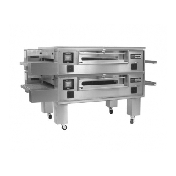
PS840 Series
Electric
Domestic & Std. Export
ENGLISH
PS840 Series Electric Ovens
Model:
•
PS840E Electric
OWNER'S OPERATING AND
INSTALLATION MANUAL
for domestic and standard export ovens
©2007 Middleby Marshall Inc.
is a registered trademark of Middleby Marshall, Inc. All rights reserved.
Middleby Cooking Systems Group • 1400 Toastmaster Drive • Elgin, IL 60120 • (847)741-3300 • FAX (847)741-4406
Combinations:
•
Single Oven
•
Double Oven (Two-Stack)
•
Triple Oven (Three-Stack)
P/N 60253
November 18, 2008 Rev. B
Advertisement
Table of Contents

Subscribe to Our Youtube Channel
Related Manuals for Middleby Marshall PS840E


Summary of Contents for Middleby Marshall PS840E
- Page 1 INSTALLATION MANUAL for domestic and standard export ovens ©2007 Middleby Marshall Inc. is a registered trademark of Middleby Marshall, Inc. All rights reserved. Middleby Cooking Systems Group • 1400 Toastmaster Drive • Elgin, IL 60120 • (847)741-3300 • FAX (847)741-4406...
- Page 2 This manual must be kept in a prominent, easily reachable location near the oven. It is suggested to obtain a service contract with a Middleby Marshall Authorized Service Agent. WARNING FOR YOUR SAFETY, DO NOT STORE OR USE GASOLINE OR OTHER FLAMMABLE VAPORS AND LIQUIDS IN THE VICINITY OF THIS OR ANY OTHER APPLIANCE.
- Page 3 © 2003 - Middleby Marshall, A Middleby Company. The Middleby Marshall logo is a registered trademark of Middleby Marshall, A Middleby Company. Middleby Marshall Inc. • 1400 Toastmaster Drive • Elgin, Illinois 60120-9272 U.S.A. • (847) 741-3300 • FAX: (847) 741 4406...
-
Page 4: Table Of Contents
TABLE OF CONTENTS Page Page SECTION 3 – OPERATION ..........19 SECTION 1 – DESCRIPTION ..........1 LOCATION AND DESCRIPTION OF CONTROLS 19 OVEN USES ............1 II. NORMAL OPERATION, STEP-BY-STEP ....20 II. OVEN COMPONENTS ..........1 A. Main Screen ..........20 A. -
Page 5: Section 1 - Description
SECTION 1 – DESCRIPTION Figure 1-1. Oven Components I. OVEN USES PS840 Series Ovens can be used to bake and/or cook a wide variety of food products, such as pizza, pizza –type products, cookies, sandwiches and others. II. OVEN COMPONENTS – see Figure 1-1. Conveyor Drive Motor: Moves the conveyor. -
Page 6: Oven Specifications
I. OVEN SPECIFICATIONS Table 1-1 Dimensions Single Oven Double Oven Triple Oven Overall Height 48-3/16″ (1219mm) 62-3/4″ (1575mm) 78-11/16″ (1981mm) Overall Depth 60″ (1524mm) 60″ (1524mm) 60″ (1524mm) Overall Length 76-1/2″ (1930mm) 76-1/2″ (1930mm) 76-1/2″ (1930mm) 32″ ″ ″ ″ ″ Conveyor Model 33-1/2″... -
Page 7: Section 2 - Installation
SECTION 2 – INSTALLATION WARNING – After any conversions, readjustments, or service work on the oven: • Check that the ventilation system is in operation. WARNING - Keep the appliance area free and clear of combustibles. WARNING – The oven must be installed on an even (level) non-flammable flooring and any adjacent walls must be non-flammable. -
Page 8: Installation Kit
PS840 24″ ″ ″ ″ ″ OVEN INSTALLATION REQUIRED KITS AND EQUIPMENT PS840 PS840 PS840 PS840 Electric Oven Single Oven DoubleOven TripleOven Installation Option Base w/ OptionBase w/ OptionBase w/ TYPE OF INSTALLATION 15″ Legs, 6″ Legs, Casters& Top Casters & Top Casters &... - Page 9 PS840 32″ ″ ″ ″ ″ OVEN INSTALLATION REQUIRED KITS AND EQUIPMENT PS840 PS840 PS840 PS840 Electric Oven Single Oven DoubleOven TripleOven Installation Option Base w/ OptionBase w/ OptionBase w/ TYPE OF INSTALLATION 15″ Legs, 6″ Legs, Casters& Top Casters & Top Casters &...
- Page 10 Figure 2-2A. Model PS840 24″ ″ ″ ″ ″ Single Oven Option Base with Legs and Top HARD WARE BA G 5, 6, 7, 10 & 11 PARTS LIST FOR PS840 SERIES 24″ ″ ″ ″ ″ SINGLE OVEN OPTION - BASE w/15″ ″ ″ ″ ″ LEGS & TOP P/N 61123 ITEM NO.
- Page 11 Figure 2-2B. Model PS840 32″ ″ ″ ″ ″ Single Oven Option Base with Legs and Top HARD WARE BA G 5, 6, 7, 10 & 11 PARTS LIST FOR PS840 32″ ″ ″ ″ ″ SERIES SINGLE OVEN OPTION - BASE w/15″ ″ ″ ″ ″ LEGS & TOP P/N 59720 ITEM NO.
- Page 12 Figure 2-3A. Model PS840 24″ ″ ″ ″ ″ Double Oven Option Base with Legs and Top HARD WARE BA G 5, 6, 7, 10 & 11 PARTS LIST FOR PS840 SERIES 24″ ″ ″ ″ ″ DOUBLE OVEN OPTION - BASE w/6″ ″ ″ ″ ″ LEGS & TOP P/N 61457 ITEM NO.
- Page 13 Figure 2-3B. Model PS840 32″ ″ ″ ″ ″ Double Oven Option Base with Legs and Top HARD WARE BA G 5, 6, 7, 10 & 11 PARTS LIST FOR PS840 SERIES 32″ ″ ″ ″ ″ DOUBLE OVEN OPTION - BASE w/6″ ″ ″ ″ ″ LEGS & TOP P/N 59725 ITEM NO.
- Page 14 Figure 2-4A. Model PS840 24″ ″ ″ ″ ″ Triple Oven Option Base with Outriggers and Top HARDWARE BAG 7, 8, 9, 10, 11, 12, 13, 14, & 17 PARTS LIST FOR PS840 SERIES 24″ ″ ″ ″ ″ TRIPLE OVEN OPTION - BASE w/CASTERS & TOP P/N 61458 ITEM NO.
- Page 15 Figure 2-4B. Model PS840 32″ ″ ″ ″ ″ Triple Oven Option Base with Outriggers and Top HARDWARE BAG 7, 8, 9, 10, 11, 12, 13, 14, & 17 PARTS LIST FOR PS840 SERIES 32″ ″ ″ ″ ″ TRIPLE OVEN OPTION - BASE w/CASTERS & TOP P/N 59726 ITEM NO.
-
Page 16: Ventilation System
B. Recommendations III. VENTILATION SYSTEM NOTE THAT THE HOOD DIMENSIONS SHOWN IN F I G U R E 2 - 5 A R E R E C O M M E N D A T I O N S O N L Y . IMPORTANT LOCAL, NATIONAL AND INTERNATIONAL CODES M U S T B E F O L L O W E D W H E N I N S T A L L I N G T H E... -
Page 17: Assembly
Figure 2-6. Leg extension and casters installation IV. ASSEMBLY A. Top Panel and Base Pad Assembly Finished sides of leg extension face Install the four leg extensions onto the base pad using corner of base the 3/8″-16 × 1″ screws, 3/8″ flat washers, and 3/8″... -
Page 18: Restraint Cable Installation
Electric oven cavities be stacked BY AUTHORIZED PERSONEL. Figure 2-10. Top panel installation Contact your Middleby Marshall Authorized Service Agent for complete stacking instructions. Stack an oven cavity on top of the lower oven. Check #10-32 × 2-1/2″... -
Page 19: Conveyor Installation
D. Conveyor Installation Figure 2-13. Conveyor placement Unfold the conveyor as shown in Figure 2-12. Then, begin to slide the conveyor into the end of the oven. The conveyor can only be installed from the end of the oven with the drive motor. Crumb tray support Continue moving the conveyor into the oven until the... -
Page 20: Final Assembly
If it is necessary to add or remove conveyor links to CONVEYOR BELT REVERSAL achieve the correct tension, OR if it is necessary to Conveyor belt reversal consists of three steps: reverse the conveyor belt for correct orientation, the belt will need to be removed from the conveyor frame. - Page 21 III. ELECTRICAL CONNECTION INFORMATION IV. ELECTRIC SUPPLY FOR ELECTRICALLY FOR PS840E-SERIES OVENS. HEATED OVENS Power requirements for electrically heated ovens are usually 208 - 240VAC, 3-phase, 4-wire (3 ‘hot’, 1 ground), although WARNING ovens built for export can have power requirements of 380VAC Authorized supplier personnel normally accom- and 480VAC.
-
Page 22: Connection
UTILITY ROUGH-IN DIMENSIONS AND POSITIONING FOR PS840-SERIES OVENS WARNING DO NOT USE CONDUIT FOR GROUND CONNECTION. To Oven CAUTION IT IS RECOMMENDED THAT THE OVEN BE PLACED UNDER A VENTILATION To Oven HOOD FOR ADEQUATE AIR SUPPLY AND VENTILATION. ELECTRIC SUPPLY TO BE PROVIDED BY CUSTOMER Suggested dimensions are shown;... -
Page 23: Section 3 - Operation
SECTION 3 - OPERATION C. Temperature Control/Display D. Message Bar E. Energy Level E. Energy Level Indicators Indicators B. Conveyor Time Setting A. Main On/Off Button I. LOCATION AND DESCRIPTION OF CONTROLS A. Main On/Off Button C. Temperature Control/Display Turns all oven functions on or off. If the oven is below the set Displays the average set point of both right and left sides of the point, it will rise to the set point and turn the conveyor on. -
Page 24: Normal Operation, Step-By-Step
II. NORMAL OPERATION - STEP-BY-STEP- A. Daily Startup Procedure Left actual temperature - Indicates current average tem- perature of the left side of the oven. Check that the circuit breaker/fused disconnect is in the On position. Check that the window is closed. The touch panel NOTE: Right to Left temperature settings should not exceed a differential of 20 °F. -
Page 25: Quick Reference: Troubleshooting
III. QUICK REFERENCE: TROUBLESHOOTING SYMPTOM PROBLEM SOLUTION Oven will not No electrical power • Check that the circuit breaker/fused disconnect is on. Make turn On. sure the emergenct stop button is on. Oven will not Faulty contactor • Replace contactor. heat. -
Page 26: Section 4 - Maintenance
NOTE ANY replacement parts that require access to the interior of the oven may ONLY be replaced by a Middleby Marshall Authorized Service Agent. It is also strongly recommended that the 3-Month Maintenance and 6-Month Maintenance procedures in this section be performed ONLY by a Middleby Marshall Authorized Service Agent. -
Page 27: Maintenance - Monthly
Figure 4-2. Removing Air Fingers and Plates II. MAINTENANCE – MONTHLY NOTE: When removing the conveyor, refer to Figure 2-12 (in Section 2, Installation). A. Check that the oven is cool and the power is disconnected, as described in the warning at the beginning of this Section. B. -
Page 28: Maintenance - Every 3 Months
Reassemble the idler shaft into the conveyor. Make III. MAINTENANCE – EVERY 3 MONTHS sure that the bronze washer is in place between the A. Check that the oven is cool and the power is discon- two sections of the shaft. See Figure 4-4. nected, as described in the warning at the beginning of Replace the conveyor adjustment screws as shown in this Section. -
Page 29: Maintenance - Every 6 Months
Figure 4-7. Rear panel access Figure 4-6. Disassembling the drive shaft Remove eight (8) screws to remove rear panel Bearings (2 total) Blower belt Blower motor Loosen four (4) screws to adjust motor position and belt tension IV. MAINTENANCE - EVERY 6 MONTHS E. - Page 30 V. KEY SPARE PARTS – Available separately. See Figure 4-8. 11, 12 19, 20, 21 13, 14, 15, 16 Figure 4-8. Key Spare Parts ITEM QTY. DESCRIPTION 60190 DIGITAL DISPLAY, PROGRAMMED 58920 CONVEYOR DRIVE MOTOR W/PICKUP ASSY. 58679 CONVEYOR SPEED CONTROLER 60196 KIT, THERMOCOUPLE 6″...
-
Page 31: Section 5 - Troubleshooting
Turn temperature Set the conveyor speed Start the oven again. If the oven still does not control to correct control at correct setting. heat, call your Middleby Marshall Service Agency. setting. Verify the food PROBLEM: preparation process. CONVEYOR WILL NOT HOLD PROPER SPEED... - Page 32 SECTION 6 - WIRING DIAGRAM...
- Page 34 NOTES...
- Page 35 NOTICE During the warranty period, ALL parts replacement and servicing should be performed by your Middleby Marshall Authorized Service Agent. Service that is performed by parties other than your Middleby Marshall Authorized Service Agent may void your warranty.
Need help?
Do you have a question about the PS840E and is the answer not in the manual?
Questions and answers