Table of Contents
Advertisement
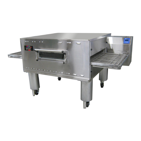
PS360G Series
Gas
Domestic & Std. Export
ENGLISH
PS360G Series Gas Ovens
Model:
PS360G Gas
PS360GWB Gas
OWNER'S OPERATING AND
INSTALLATION MANUAL
f o r d o m e s t i c a n d s t a n d a r d e x p o r t o v e n s
© 2019 Middleby Marshall Inc.
is a registered trademark of Middleby Marshall, Inc. All rights reserved.
Combinations:
Single Oven
Double Oven (Two-Stack)
Triple Oven (Three-Stack)
P/N: 70071
Rev. J
st
June 1
, 2019
Advertisement
Table of Contents

Related Manuals for Middleby Marshall PS360G Series


Summary of Contents for Middleby Marshall PS360G Series
- Page 1 © 2019 Middleby Marshall Inc. is a registered trademark of Middleby Marshall, Inc. All rights reserved.
- Page 2 GASOLINE OR OTHER FLAMMABLE VAPORS AND LIQUIDS IN THE VICINITY OF THIS OR ANY OTHER NOTICE APPLIANCE. Using parts other than genuine Middleby Marshall Factory manufactured parts relieves the manufacturer of all warranty ATTENTION and liability. AFFICHEZ, DANS UN LIEU VISIBLE, LE NUMÉRO DE NOTICE TÉLÉPHONE D’URGENCE DE VOTRE FOURNISSEUR...
- Page 3 THE FOREGOING WARRANTY IS EXCLUSIVE AND IN LIEU This warranty is effective on Middleby Marshall equipment OF ALL OTHER EXPRESS AND IMPLIED WARRANTIES sold on, or after January 1 , 2007.
-
Page 4: Table Of Contents
TABLE OF CONTENTS Page SECTION 1 - DESCRIPTION SECTION 3 - OPERATION I. DESCRIPTION OF CONTROLS OVEN USES / MODELS ...…….………..1 A. Control Keys……………………………….19 II. OVEN COMPONENTS …….……………1 B. Display Features…………………………..20 Conveyor Motor Drive II. NORMAL OPERATION Crumb Pans A. Starting the Oven………………………….20 C. -
Page 5: Section 1 - Description Page
SECTION 1 - DESCRIPTION OVEN USES The PS360G Series ovens can be used to bake and/or cook a wide variety of products, such as pizza, pizza- type products, cookies, sandwiches and others. II. OVEN COMPONENTS – See Figure 1-1 A. Conveyor Drive Motor (inside cabinet): Moves the Conveyor Belting (65756) B. -
Page 6: Oven Specifications
III. OVEN SPECIFICATIONS – PS360G Single Oven Double Oven Triple Oven Table 1-1 Dimensions Overall Height 48.52” (1232.4 mm) 67.21” (1707.2 mm) 76.93” (1954.1 mm) Overall Depth 57.50” (1458 mm) 57.50” (1458 mm) 57.50” (1458 mm) Overall Length 92.00” (2337 mm) 92.00”... - Page 7 I. OVEN SPECIFICATIONS – PS360GWB Single Oven Double Oven Triple Oven Table 1-1 Dimensions Overall Height 48.52” (1232.4 mm) 67.71” (1719.9 mm) 77.43” (1966.8 mm) Overall Depth 63.27” (1607 mm) 63.27” (1607 mm) 63.27” (1607 mm) Overall Length 92.00” (2337 mm) 92.00”...
-
Page 8: Section 2 - Installation I. General
SECTION 2 - INSTALLATION I. GENERAL WARNING – After any conversions, readjustments, or service work on the oven: Perform a gas leak test Test for proper combustion and gas supply Test for correct air supply, particularly to the burner Check that the ventilation system is in operation blower. -
Page 9: Single Oven Base/Top Kit
II. PS360G OVEN INSTALLATION – REQUIRED KITS & EQUIPMENT TYPE OF INSTALLATION PS360G Single Oven Kit Double Oven Kit Triple Oven Kit Installation Kit Base w/ 15” Legs, Base w/ 10” Legs, Base, Casters & Casters & Top Casters & Top PS360G Single Gas Oven 69977 One (1) PN 69669... -
Page 10: Double Oven Base/Top Kit
A. PN 69669 – SINGLE OVEN BASE/TOP KIT 5 ... -
Page 11: Triple Oven Base/Top Kit
B. PN 70274 – DOUBLE OVEN BASE/TOP KIT 6 ... -
Page 12: Oven Layouts A. Single Oven Layout
C. PN 70275 – TRIPLE OVEN BASE/TOP KIT 7 ... -
Page 13: Double Stacked Layout
8 ... -
Page 14: Triple Stacked Layout
9 ... -
Page 15: Ventilation System
II. VENTILATION SYSTEM B. Recommendations NOTE THAT THE HOOD DIMENSIONS SHOWN IN FIGURE 2-5 ARE RECOMMENDATIONS ONLY. LOCAL, NATIONAL, AND INTERNATIONAL CODES MUST BE IMPORTANT FOLLOWED WHEN INSTALLING THE VENTILATION SYSTEM. ANY APPLICABLE CODES SUPERCEDE THE Where national or local codes require the RECOMMENDATIONS SHOWN IN THIS MANUAL. -
Page 16: Assembly
III. ASSEMBLY Fig 2-6. Leg Extension and Caster Installation Top Panel and Base Pad Assembly Install the four leg extensions onto the base pad using the 1/2”-13 x 1-1/4” screws, 1/2” flat washers and 1/2” lockwashers supplied in the Base Pad Kit. See Figure 2-6. -
Page 17: Stacking
After connecting the restraint cable, move the oven to its final location. Adjust the bottom (hex) sections of Contact your Middleby Marshall authorized Service Agent the adjustable legs so that the casters are off the floor. for complete stacking instructions. -
Page 18: Conveyor Installation
D. Conveyor Installation Figure 2-13 Unfold the conveyor as shown in Figure 2-12. Then begin to slide the conveyor into the end of the oven. The conveyor can only be installed form the side of the oven where the drive motors are located. Continue moving the conveyor into the oven until the frame protrudes equally from each end of the oven. -
Page 19: Electrical Supply
If it is necessary to add or remove conveyor links to REVERSING THE CONVEYOR BELT achieve the correct tension, OR if it is necessary to Remove the conveyor from the oven and find the master link reverse the conveyor belt for correct orientation, the belt location. -
Page 20: Gas Supply
The terms of the oven’s warranty require all Three oven cavities: 1,200 CFH meter start-ups, conversions and service work to be performed by a Middleby Marshall Authorized Gas Line Service Agent. DEDICATED GAS LINE from the gas meter to the oven ... -
Page 21: Connection
1. Disconnect pressure feedback connection (if applicable). Connection 2. Connect a suitable pressure gauge to pipe line or to outlet Check the oven’s gas supply requirements before making pressure tap of gas control concerned, to measure burner the gas utility connections. Gas supply requirements are pressure (measuring point must be as near to burner as listed on the oven’s serial plate and in Table 1-4. -
Page 22: Adjusting Min Pressure Setting
If minimum rate pressure needs adjustment, use an 5 Figure 2-20. Burner Components mm wrench to turn adjustment screw for minimum pressure setting (clockwise to increase or counter- BURNERS clockwise to decrease pressure), while holding the 8 mm wrench and 8 mm adjustment nut in place, until the desired minimum outlet pressure is obtained. -
Page 23: Section 3 - Operation
SECTION 3 - OPERATION I. DESCRIPTION OF CONTROLS – USER INTERFACE The PS360G oven control performs a variety of functions, including Temperature control Belt speed control Upper/lower blower speed setting Energy management Oven diagnostics and system testing ... -
Page 24: Display Features
B. Display Features STATUS INDICATOR: “BAKING” appears when the SETPOINT: oven is in baking mode. No Set point (baking) text here indicates that the temperature is oven is in IDLE mode. displayed here. BAKIN 350 F 4:00 256 F HEAT HEAT STATUS: Alternating display indicates: “HEAT”... -
Page 25: Adjusting The Belt Time
C. Adjusting the Belt Time To adjust the belt time, press and hold the button until the belt time display flashes. Press the BELT button until the desired belt time is displayed. Press the button to set and save the new time value. BELT If the button is not pressed, the new time will be present only until the oven is turned OFF. -
Page 26: Changing Energy Mode Status
B. Changing Energy Mode Status (Run Mode) If he photo eye should ever fail to operate, baking mode can be continually engaged by disabling the energy mode. A service call should be made in the interim, as energy use will be considerably higher without the energy mode. -
Page 27: Energy Management Information
D. Energy Management Information The PS360G reduces energy usage in two ways over most competitive ovens: Modulating gas control IDLE/ BAKING mode control (Energy Saving Mode) The modulating gas valve within the oven controls pressure of the delivered gas to the burners to increase or reduce the energy input as needed to maintain temperature instead of cycling a gas valve on and off. -
Page 28: Troubleshooting Information
PS360G TROUBLESHOOTING INFORMATION A. Troubleshooting Guide SYMPTOM POSSIBLE CAUSES SOLUTIONS 1. Check plug at wall 1. Power not connected Nothing displayed on controller 2. Main breaker not on 2. Check main breaker 3. Control circuit breaker tripped 3. Check control breaker No problem –... -
Page 29: Alerts, Errors And Remedies
B. ALERTS, ERRORS & REMEDIES SYMPTOM PROBABLE CAUSE REMEDY Press enter key to silence BELT PROBE 1 OPEN on display and Temperature Probe number 1 alarm and resume operation. audible alarm sounds. (upper left) is open. Control will compensate for lost probe. -
Page 30: Section 4 - Maintenance
NOTE ANY replacement parts that require access to the interior of the oven may ONLY be replaced by a Middleby Marshall Authorized Service Agent. It is also strongly recommended that the 3-Month Maintenance and 6-Month Maintenance procedures in this section be performed ONLY by a Middleby Marshall Authorized Service Agent. -
Page 31: Maintenance - Monthly
II. MAINTENANCE – MONTHLY NOTE: When removing the conveyor, refer to Figure 2-12 (in Section 2, Installation). Check that the oven is cool and the power is disconnected as described in the warning at the beginning of this section. Remove the crumb trays from the oven. Lift the drive end of the conveyor slightly, and push it forward into the oven. -
Page 32: Maintenance - 3 Month
III. MAINTENANCE – EVERY 3 MONTHS Reassemble the idler shaft into the conveyor. Make sure that the bronze washer is in place between the two sections of the shaft. See Figure A. Check that the oven is cool and the power is disconnected, 4-4. -
Page 33: Maintenance - 6 Month
IV. MAINTENANCE - EVERY 6 MONTHS A. Check that the oven is cool and the power is disconnected, as described in the warning at the beginning of this Section. B. For gas ovens, inspect and clean the burner nozzle and the spark electrode assembly. C. -
Page 34: Key Spare Parts
KEY SPARE PARTS PS360G/GWB GAS OVEN ITEM DESCRIPTION 71986 Digital Display, Programmed 65756 Motor, Conveyor Drive 65566 Conveyor Control Board 72531 Inverter, 2 HP Lenze (230V Input/ 69614 69079 Power Supply, 24VDC, 120W 69583 Rotation Sensor (1 per motor) 36451 Fan,Cooling 63909 Switch, Door Interlock... -
Page 35: Section 5 - Wiring Diagrams
SECTION 5 – WIRING DIAGRAMS 30 ... - Page 36 31 ...
- Page 37 32 ...
- Page 38 33 ...
- Page 39 ADDENDUM PS360GWB Propane Conversion Kit # 72870 Instructions Part Number 72869 Revision B 34 ...
- Page 40 NOTES 35 ...
- Page 41 NOTES 36 ...
Need help?
Do you have a question about the PS360G Series and is the answer not in the manual?
Questions and answers