NEC NP2200 Installation And Assembly Manual
Ceiling mount for np1150, np2150, np3150, np3151w, np1250, np2250, np3250 and np3250w projector
Hide thumbs
Also See for NP2200:
- Install manual (9 pages) ,
- Quick setup manual (7 pages) ,
- Technical specification (2 pages)
Advertisement
Table of Contents
NEC Display Solutions of America, Inc.
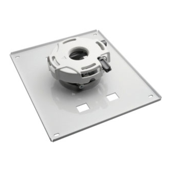
Installation and Assembly - Ceiling Mount for NEC
NP1150, NP2150, NP3150, NP3151W, NP1250, NP2250,
NP3250 and NP3250W Projector
Model: NP3250CM
Maximum Load Capacity: 50 lb (22.7 kg)
Features:
TM
• ImageLock
alignment prevents picture sag or drift
• Wrench access slot for easier flush mount installations
• Exclusive aluminum track quick release
1 of 9
ISSUED: 06-16-09 SHEET #: 055-XXXX-1
For customer care call 1-800-729-0307 or 708-865-8870.
Visit the Peerless Web Site at www.peerlessmounts.com
Advertisement
Table of Contents

Related Manuals for NEC NP2200


Summary of Contents for NEC NP2200
- Page 1 NEC Display Solutions of America, Inc. Installation and Assembly - Ceiling Mount for NEC NP1150, NP2150, NP3150, NP3151W, NP1250, NP2250, NP3250 and NP3250W Projector Model: NP3250CM Maximum Load Capacity: 50 lb (22.7 kg) Features: • ImageLock alignment prevents picture sag or drift •...
-
Page 2: Table Of Contents
NOTE: Read entire instruction sheet before you start installation and assembly. WARNING • Do not begin to install your Peerless product until you have read and understood the instructions and warnings con- tained in this Installation Sheet. If you have any questions regarding any of the instructions or warnings, call Peerless customer care at 1-800-729-0307. -
Page 3: Parts List
Parts List Description Qty. Part # A projector mount assembly 055-2803 B 4 mm security allen wrench 560-9646 C #10-32 x 3/8" serrated washer head socket pin screw 520-2151 D #10-32 x 1/4" socket pin screw 520-2196 E flat washer 540-1078 F #14 x 2.5 phillips hex head wood screw 5S1-015-C04... -
Page 4: Installation To Wood Joist Ceilings
Installation To Wood Joist Ceilings WARNING • Installer must verify that the supporting surface will safely support the combined load of the equipment and all attached hardware and components. • Tighten wood screws so that projector mount assembly is firmly attached, but do not overtighten. Overtightening can damage the screws, greatly reducing their holding power. -
Page 5: Installation To Concrete Ceilings
Installation to Concrete Ceilings Drill two 1/4" (6 mm) dia. holes to a minimum depth of 2.5" (64 mm). Attach projector mount assembly (A) using two concrete anchors (G), two flat washers (E), and two #14 x 2.5" wood screws (F) as shown in Illustration A and 1, 2, and 3 (below). -
Page 6: Installation To Threaded Rods
Installation to Threaded Rod (Not evaluated by UL - Professional installation only) Thread two 1/4-20 hex thin nylon-insert locknuts (not included) on two 1/4-20 threaded rods (not included) to the desired height of projector mount assembly. Attach projector mount assembly (A) to the two 1/4-20 threaded rods using two 1/4-20 hex thin nylon-insert locknuts as shown in figure 4.1 or figure 4.2. -
Page 7: Installation To Extension Columns / Ceiling Plate
Installation to Extension Column / Ceiling Plate NOTE: Refer to accompanying instructions with ceiling plates (sold separately) for installing these models to ceiling. Screw projector mount assembly (A) onto extension column as shown in figure 5.1. NOTE: For 3/4" extension columns, reducer ACC 913 will be required as shown in figure 5.2. Tighten swivel stop screw against extension column, flush mount tube or reducer using 4 mm security allen wrench (B) as shown in figure 5.3. -
Page 8: Attaching Adapter Plate To Projector
Align shoulder on connection block opposite notch in adapter plate. Attach adapter plate (I) to connection block from projector mount assembly (A) using two #10-32 x 3/8" serrated washer head socket pin screws (C) as shown. CONNECTION BLOCK SHOULDER NOTCH INDICATES FRONT OF PROJECTOR Note: The projector you are installing may differ in appearance from the sample illustrated below. -
Page 9: Projector Alignment
WARNING • Always use an assistant or mechanical lifting equipment to safely lift and position the projector mount. Slide connection block with projector into projector mount IMPORTANT: For security installations, insert assembly (A) as shown. Tighten captive screw to secure one #10-32 x 1/4"...
Need help?
Do you have a question about the NP2200 and is the answer not in the manual?
Questions and answers