Table of Contents
Advertisement
Quick Links
See also:
User Manual
Advertisement
Table of Contents

Related Manuals for Asus P2B-D


Summary of Contents for Asus P2B-D
- Page 1 ® P2B-D/P2B-DS ® Dual Pentium III / II Motherboard USER’S MANUAL Special Features • P2B-DS • Adaptec 7890 SCSI Chipset • Adaptec 3860 SCSI Transceiver...
- Page 2 Product warranty or service will not be extended if: (1) the product is repaired, modified or altered, unless such repair, modification of alteration is authorized in writing by ASUS; or (2) the serial number of the product is defaced or missing.
- Page 3 WWW: www.asus.com FTP: ftp.asus.com/Pub/ASUS ASUS COMPUTER GmbH (Europe) Marketing Address: Harkortstr. 25, 40880 Ratingen, BRD, Germany Fax: +49-2102-4420-66 Email: sales@asuscom.de Technical Support Hotline: MB/Other: +49-2102-9599-0 Notebook: +49-2102-9599-10 Fax: +49-2102-9599-11 Online Support: www.asuscom.de/de/support WWW: www.asuscom.de FTP: ftp.asuscom.de/pub/ASUSCOM ASUS P2B-D/P2B-DS User’s Manual...
-
Page 4: Table Of Contents
How This Manual Is Organized ............7 Item Checklist ..................7 II. FEATURES ..................8 Features ....................8 The ASUS P2B-D/P2B-DS Motherboard ........... 9 III. INSTALLATION ................10 ASUS P2B-D/P2B-DS Motherboard Layout ........10 Installation Steps ................12 1. Motherboard Settings ..............12 Jumper Settings .............. - Page 5 ASUS Contact Information ........... 61 VI. DESKTOP MANAGEMENT ............62 Desktop Management Interface (DMI) ..........62 Introducing the ASUS DMI Configuration Utility ....62 Starting the ASUS DMI Configuration Utility ...... 62 VII. ADAPTEC SCSI SELECT ............65 Configuring the SCSI Adapter ............65 VIII.
-
Page 6: Federal Communications Commission Statement
Radio Interference Regulations of the Canadian Department of Communications. This Class B digital apparatus complies with Canadian ICES-003. Cet appareil numérique de la classe B est conforme à la norme NMB-003 du Canada. ASUS P2B-D/P2B-DS User’s Manual... -
Page 7: Introduction
(1) Bag of spare jumpers (1) Support drivers and utilities (1) This Motherboard User’s Manual (1) ASUS C-P2T PC100 Rev. 1.02 or later (1) Adaptec 7800 Family Manager Set User’s Manual (optional) 68-pin Ultra2 SCSI cable with terminator (optional) 68-pin Fast & Wide SCSI cable (optional) -
Page 8: Features
100MHz bus speed requirement. • Wake-On-LAN: Supports Wake-On-LAN activity through an optional ASUS PCI-L101 10/100 Fast Ethernet PCI card (see IX. ASUS PCI-L101 LAN Card) or a similar ethernet card. • Adaptec SCSI Chipset: Features Adaptec AIC-7890 Ultra2 SCSI chipset (optional) that... -
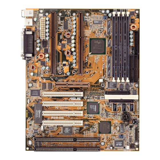
Page 9: The Asus P2B-D/P2B-Ds Motherboard
II. FEATURES The ASUS P2B-D/P2B-DS Motherboard Floppy Connector SEC CPU Slots Intel 440BX AGPset 4 DIMM Sockets T: PS/2 Mouse B: PS/2 Keyboard T: USB Port 1 B: USB Port 2 COM 1 (Bottom) Parallel (Top) Serial (Bottom) COM 2... -
Page 10: Installation
III. INSTALLATION ASUS P2B-D/P2B-DS Motherboard Layout PS/2 CPU_FAN MOUSE (TOP PORT) KEYBOARD (BOTTOM) BUS FREQ USB 1(TOP PORT) USB 2 (BOTTOM) COM 1 Intel 440BX AGPset COM 2 PWR_FAN Adaptec Accelerated Graphics Port AIC-3860 Transceiver 68-Pin Wide SCSI Connector Multi-I/O... -
Page 11: Hardware Monitor
34 SB-LINK™ Connector (6-1 pins) (O/R) 23) SMB p. 34 SMBus Connector (3 pins) (O/R) The onboard hardware monitor uses the address 290H-297H so legacy ISA cards must not use this address, otherwise conflicts will occur. O/R: Optional/Reserved for future use. ASUS P2B-D/P2B-DS User’s Manual... -
Page 12: Installation Steps
3. Hold components by the edges and try not to touch the IC chips, leads or connectors, or other components. 4. Place components on a grounded antistatic pad or on the bag that came with the component whenever the components are separated from the system. ASUS P2B-D/P2B-DS User’s Manual... -
Page 13: Jumper Settings
<Delete> during bootup and enter BIOS setup to re-enter user preferences. Short the solder points to clear CMOS P2B-D/DS Real Time Clock RAM (CLRTC) 2. Keyboard Power Up (KBPK) This allows you to disable or enable the keyboard power up function. Set to Enable if you want to use your keyboard (by pressing <Spacebar>) to power up... - Page 14 1 2 3 1 2 3 7.0x (7/1) 7.5x (15/2) 8.0x (8/1) P2B-D/DS CPU Core-to-Bus Frequency Multiple WARNING! Frequencies above 100MHz exceed the specifications for the on- board Intel Chipset and are not guaranteed to be stable. ASUS P2B-D/P2B-DS User’s Manual...
- Page 15 66MHz [2-3] [1-2] [1-2] [2-3] [2-3] [1-2] [1-2] For updated processor settings, please visit ASUS’ web site (see ASUS CONTACT INFORMATION). NOTES: Overclocking your processor is not recommended. It may result in a slower speed. Voltage Regulator Output Selection (VID) is not needed for the Pentium III/ II processor because it sends a VID signal directly to the onboard power controller.
- Page 16 III. INSTALLATION (This page was intentionally left blank.) ASUS P2B-D/P2B-DS User’s Manual...
-
Page 17: System Memory (Dimm)
BIOS shows SDRAM memory on bootup screen. • 8 chips/side modules do not support ECC, only 9 chips/side modules support ECC. • Single-sided DIMMs come in 16, 32, 64, 128MB; double-sided come in 32, 64, 128, 256MB. ASUS P2B-D/P2B-DS User’s Manual... -
Page 18: Dimm Memory Installation Procedures
60 Pins 88 Pins Lock (FRONT) P2B-D/DS 168-Pin DIMM Memory Sockets The DIMMs must be 3.3Volt unbuffered SDRAMs. To determine the DIMM type, check the notches on the DIMMs (see figure below). 168-Pin DIMM Notch Key Definitions (3.3V) DRAM Key Position... -
Page 19: Central Processing Unit (Cpu)
You may install an auxiliary fan, if necessary. Other Important Items Intel Pentium III / II Processor in an SEC cartridge ASUS C-P2T PC100 CPU Termination Card ASUS P2B-D/P2B-DS User’s Manual... - Page 20 CPU will overheat. You may install an auxiliary fan to provide adequate circula- tion across the processor’s passive heatsink. Push each end of the clamps until they lock The thermal pad & SEC cartridge should not have a gap! SEC Cartridge with Heatsink (Top View) ASUS P2B-D/P2B-DS User’s Manual...
- Page 21 The procedures shown here are for installing the AAVID heatsink with fan.) Push lock inward IMPORTANT: If you are installing only one processor, you must terminate the empty slot with the ASUS C-P2T PC100 CPU termination card to maintain signal strength. ASUS C-P2T PC100 CPU Termination Card IMPORTANT: Use only the ASUS C-P2T PC100 CPU termination card (Rev.
-
Page 22: Asus Smart Thermal Solutions
ASUS S-P2FAN has an integrated thermal sensor located near the center of the CPU heat source. The sensor is optimized by ASUS to give the most accurate reading of the CPU tempera- ture, thus provides the best protection to your computer system. -
Page 23: Recommended Heatsinks For Slot 1 Processors
The recommended heatsinks for the Slot 1 processors are those with three-pin fans, such as the ASUS Smart Fan, that can be connected to the motherboard’s CPU fan connector. These heatsinks, such as the Elan Vital Heatsink with Fan, dissipate heat more efficiently and with an optional hardware monitor, they can monitor the fan’s... -
Page 24: Expansion Cards
Interrupt number and address. Make sure that no two devices use the same IRQ or your computer will experience problems when those two devices are in use at the same time. ASUS P2B-D/P2B-DS User’s Manual... -
Page 25: Assigning Dma Channels For Isa Cards
Accelerated Graphics Port This motherboard provides an accelerated graphics port (AGP) slot to support a new generation of graphics cards with ultra-high memory bandwidth, such as the ASUS AGP-V2740 3D Multimedia Accelerator. P2B-D/DS Accelerated Graphics Port (AGP) -
Page 26: External Connectors
The system will direct IRQ12 to the PS/2 mouse if one is detected. If not de- tected, expansion cards can use IRQ12. See “PS/2 Mouse Function Control” in BIOS Features Setup of the BIOS SOFTWARE. PS/2 Mouse (6-pin Female) ASUS P2B-D/P2B-DS User’s Manual... - Page 27 (Pin 5 is removed to prevent inserting in the wrong orienta- tion when using ribbon cables with pin 5 plugged). NOTE: Orient the red stripe on the floppy ribbon cable to Pin 1 Floppy Drive Connector Pin 1 P2B-D/DS Floppy Disk Drive Connector ASUS P2B-D/P2B-DS User’s Manual...
- Page 28 SCSI drive and select the boot disk through BIOS Features Setup. NOTE: Orient the red stripe on the IDE ribbon cable to Pin 1 Primary IDE Connector PIN 1 Secondary IDE Connector P2B-D/DS IDE Connectors ASUS P2B-D/P2B-DS User’s Manual...
- Page 29 Power Supply Fan Power Chassis Fan Power NOTE: If you are installing two processors, you may connect the fan from the second heatsink to either the power supply or chassis fan connector. P2B-D/DS 12Volt Cooling Fan Power ASUS P2B-D/P2B-DS User’s Manual...
- Page 30 IRRX For the infrared feature to be available, you must connect the optional Infrared P2B-D/DS Infrared Module Connector (IrDA) module to the motherboard 11. ATX Power Supply Connector (20-pin ATXPWR) This connector connects to an ATX power supply. The plug from the power supply will only insert in one orientation because of the different hole sizes.
- Page 31 12. Wake-On-LAN (3-pin WOLCON) This connector connects to LAN cards with a Wake-On-LAN output, such as the ASUS PCI-L101 (see section IX. ASUS LAN Card). The connector powers up the system when a wakeup packet or signal is received through the LAN card.
- Page 32 20. Speaker Connector (SPEAKER) This 4-pin connector connects to the case-mounted speaker. Keyboard Lock Speaker Power LED Connector Reset SW MSG LED ATX Power Switch* SMI Lead * Requires an ATX power supply. P2B-D/DS System Panel Connections ASUS P2B-D/P2B-DS User’s Manual...
- Page 33 SE Mode Disk 1 Disk 2 Disk 3 Ultra2 SCSI Wide SCSI Connector Connector P2B-D/DS Mixed Ultra2 and Single-Ended Device Configuration Ultra2 SCSI uses the same connectors and cables as UltraSCSI, so upgrading is easy and cost-effective. ASUS P2B-D/P2B-DS User’s Manual...
- Page 34 The SMBus or System Management Bus is a specific implementation of an I C bus, which is a multi-master bus, that is, multiple chips can be connected to the same bus and each one can act as a master by initiating data transfer. P2B-D/DS SMBus Connector ASUS P2B-D/P2B-DS User’s Manual...
-
Page 35: Power Connection Procedures
Shut down the computer?. The system will give three quick beeps after about 30 seconds and then power off after Windows shuts down. NOTE: The message “You can now safely turn off your computer” will not appear when shutting down with ATX power supplies. ASUS P2B-D/P2B-DS User’s Manual... -
Page 36: Bios Software
To save your current BIOS, type [1] at the Main Menu and then press <Enter>. The Save Current BIOS To File screen appears. Type a filename and the path, for example, A:\440BX-1 and then press <Enter>. ASUS P2B-D/P2B-DS User’s Manual... - Page 37 BIOS update, press Y to start the update. The utility starts to program the new BIOS information into the flash ROM. When the program- ming is finished, Flashed Suc- cessfully will be displayed. Follow the onscreen instructions to continue. ASUS P2B-D/P2B-DS User’s Manual...
-
Page 38: Managing And Updating Your Motherboard's Bios
Updating BIOS Procedures (only when necessary) 1. Download an updated ASUS BIOS file from the Internet (WWW or FTP) or a BBS (Bulletin Board Service) (see ASUS CONTACT INFORMATION on page 3 for details) and save to the disk you created earlier. -
Page 39: Bios Setup
Reset button on the system case. You can also restart by turning the system off and then back on again. But do so only if the first two methods fail. When you invoke Setup, the CMOS SETUP UTILITY main program screen will appear with the following options: ASUS P2B-D/P2B-DS User’s Manual... -
Page 40: Load Defaults
To set the date, highlight the “Date” field and then press either <Page Up>/<Page Down> or <+>/<–> to set the current date. Follow the month, day and year format. Valid values for month, day and year are: Month: (1 to 12), Day: (1 to 31), Year: (up to 2079) ASUS P2B-D/P2B-DS User’s Manual... - Page 41 IDE hard disks; set it to Large for drives over 528MB that do not support LBA. Large type of drive can only be used with MS-DOS and is very uncommon. Most IDE drives over 528MB support the LBA mode. ASUS P2B-D/P2B-DS User’s Manual...
- Page 42 If you are using a VGA or any higher resolution card, choose EGA/VGA. Halt On (All Errors) This field determines which types of errors will cause the system to halt. Choose from All Errors; No Errors; All,But Keyboard, All,But Diskette; and All,But Disk/Key. ASUS P2B-D/P2B-DS User’s Manual...
-
Page 43: Bios Features Setup
Be- cause of conflicts with new operating systems, for example, during installation of new softwares, you may have to set this to Disabled to prevent write errors. ASUS P2B-D/P2B-DS User’s Manual... - Page 44 This allows the enabling or disabling of the S.M.A.R.T. (Self-Monitoring, Analysis and Reporting Technology) system which utilizes internal hard disk drive monitor- ing technology. This feature is normally disabled because system resources used in this feature may decrease system performance. ASUS P2B-D/P2B-DS User’s Manual...
- Page 45 The default setting is System, where the system prompts for the User Password every time you start your system. The other option is Setup, where the system goes through its startup routine unless the Setup utility is called, when the system prompts for the Supervisor Password. ASUS P2B-D/P2B-DS User’s Manual...
-
Page 46: Chipset Features Setup
SDRAM MA Wait State (Normal) This controls the leadoff clocks for CPU read cycles. Leave on default setting. Snoop Ahead (Enabled) Enabled will allow PCI streaming. Leave on default setting. Host Bus Fast Data Ready (Disabled) Leave on default setting. ASUS P2B-D/P2B-DS User’s Manual... - Page 47 When Enabled, this field allows you to connect your floppy disk drives to the onboard floppy disk drive connector instead of a separate controller card. If you want to use a different controller card to connect the floppy disk drives, set this field to Disabled. ASUS P2B-D/P2B-DS User’s Manual...
- Page 48 Because each IDE device may have a different Mode timing (0, 1, 2, 3, 4), it is necessary for these to be independent. The default setting of Auto will allow autodetection to ensure optimal performance ASUS P2B-D/P2B-DS User’s Manual...
-
Page 49: Power Management Setup
“Power” will appear in the “Control Panel.” Choose “Advanced” in the Power Management Field. Video Off Option (Suspend -> Off ) This field determines when to activate the video off feature for monitor power management. The settings are Always On and Suspend -> Off. ASUS P2B-D/P2B-DS User’s Manual... - Page 50 4 seconds. Suspend allows the button to have a dual function where pressing less than 4 seconds will place the system in sleep mode. Regardless of the setting, holding the ATX switch for more than 4 seconds will power off the system. ASUS P2B-D/P2B-DS User’s Manual...
- Page 51 With this feature, you can remotely upload/download data to/from systems during off-peak hours. Set to Enabled to set this feature. IMPORTANT: This feature requires an ASUS PCI-L101 LAN card (see IX. ASUS LAN Card) and an ATX power supply with at least 720mA +5V standby power.
-
Page 52: Pnp And Pci Setup
ICU, you must set the field for that IRQ to Yes. For example: If you install a legacy ISA card that requires IRQ 10, then set IRQ10 Used By ISA to Yes............................ASUS P2B-D/P2B-DS User’s Manual... - Page 53 USB devices, you may set this feature to Disabled to save an extra IRQ# for expansion cards. VGA BIOS Sequence (PCI/AGP) You can select the search order for your VGA card(s). PCI/AGP will detect PCI VGA cards before AGP, and AGP/PCI will detect AGP cards before PCI VGA. ASUS P2B-D/P2B-DS User’s Manual...
-
Page 54: Load Bios Defaults
<Enter>. The system displays a confirmation message on the screen. Press <Y> and then <Enter> to confirm. Press <N> and then <Enter> to abort. This feature does not affect the fields on the Standard CMOS Setup screen. ASUS P2B-D/P2B-DS User’s Manual... -
Page 55: Supervisor Password And User Password
<Enter> instead of entering a new password when the “Enter Password” prompt appears. A message confirms the password has been disabled. NOTE: If you forget the password, see Clear Time Clock (Jumpers) in section III for procedures on clearing the CMOS. ASUS P2B-D/P2B-DS User’s Manual... -
Page 56: Ide Hdd Auto Detection
The auto-detection feature can only detect one set of parameters for a particular IDE hard drive. Some IDE drives can use more than one set. This is not a problem if the drive is new and empty. ASUS P2B-D/P2B-DS User’s Manual... -
Page 57: Save & Exit Setup
Select this option to exit the Setup utility without saving the modifications you specify during the current session. To exit without saving, highlight the “Exit Without Sav- ing” option on the main screen and then press <Enter>. ASUS P2B-D/P2B-DS User’s Manual... -
Page 58: Software Setup
Navigation Button Descriptions Motherboard Info displays information on your motherboard, BIOS, and CPU. Browse This CD allows you to see the contents of the ASUS Support CD. User’s Manual displays the motherboard user’s manual in pdf format. Technical Support Form opens up a blank Technical Support Request Form for you to fill and print out when you run into technical difficulties and need technical assistance. -
Page 59: Installation Submenu
NOTE: Will not run with LDCM installed. To uninstall a program, see Uninstalling Programs at the end of this section. ASUS LiveUpdate installs a program to help you update your BIOS or download a BIOS image file. -
Page 60: Dos Utility Submenu
DOS Utility Submenu. DOS Utility Submenu ASUS DMI Configuration Utilty provides information on using the DMI configu- ration utility. This utility is located in the DMI folder under the root directory of the support CD Flash BIOS Utility (DOS Version) provides information on the Flash BIOS utility (AFLASH.EXE). -
Page 61: Asus Contact Information
V. SOFTWARE SETUP Click here to bring up ASUS Contact Information. ASUS Contact Information ASUS P2B-D/P2B-DS User’s Manual... -
Page 62: Desktop Management
VI. DESKTOP MANAGEMENT Desktop Management Interface (DMI) Introducing the ASUS DMI Configuration Utility This motherboard supports DMI within the BIOS level and provides a DMI Con- figuration Utility to maintain the Management Information Format Database (MIFD). DMI is able to auto-detect and record information pertinent to a computer’s system such as the CPU type, CPU speed, and internal/external frequencies, and memory size. -
Page 63: Using The Asus Dmi Configuration Utility
VI. DESKTOP MANAGEMENT Using the ASUS DMI Configuration Utility NOTE: The following screen displays are provided as examples only and may not reflect the screen contents on your system. Edit DMI (or delete) Use the (left-right) cursors to move between the top menu items and the (up-down) cursors to move between the left hand menu items. - Page 64 You can load the BIOS defaults from a MIFD file and can clear all user modified and added data. You must reboot your computer in order for the defaults to be saved back into the Flash BIOS. ASUS P2B-D/P2B-DS User’s Manual...
-
Page 65: Adaptec Scsi Select
This utility is only necessary if you suspect that your SCSI disk drive has a problem. ASUS P2B-D/P2B-DS User’s Manual... - Page 66 VII. ADAPTEC SCSI SELECT (This page was intentionally left blank.) ASUS P2B-D/P2B-DS User’s Manual...
-
Page 67: Adaptec Ez-Scsi
1 Install DOS 6.x or later and start it running on your computer. 2 Insert the Adaptec EZSCSI Setup Disk into your floppy disk drive. 3 At the DOS prompt, type a:\install (assuming your 3.5” floppy is A: drive). Then press <Enter>. 4 Follow the onscreen instructions. ASUS P2B-D/P2B-DS User’s Manual... -
Page 68: Troubleshooting Tips
If Windows does not detect the host adapter, run the Add New Hardware Wizard again. This time, select No on the second screen of the wizard, then select SCSI controllers on the next screen. Select the name of your host adapter when it appears. ASUS P2B-D/P2B-DS User’s Manual... - Page 69 5 Turn the computer ON. If the new host adapter supports Plug and Play, Win- dows will install and configure it automatically. Otherwise, run Add New Hard- ware to make sure the new driver is loaded. ASUS P2B-D/P2B-DS User’s Manual...
- Page 70 Comment out the line that loads mscdex.exe in the AUTOEXEC.BAT file. • Change the /L switch on the line that loads mscdex.exe in the AUTOEXEC.BAT file so it assigns the CDROM drive the next highest logical drive letter after the hard disk drives. ASUS P2B-D/P2B-DS User’s Manual...
-
Page 71: Information For Dos/Windows 3.1X Users
ASPI manager. To learn more about these ASPI managers, including their command line option information, see the Adaptec EZSCSI Online Reference, a Windows Help application. ASUS P2B-D/P2B-DS User’s Manual... -
Page 72: Dos Formatting Utilities
You can reassign the bad block(s) to prevent data from being stored there. 6. Repeat steps 3, 4, and 5, as needed, to format or verify other disk devices. When you are finished, press Esc to exit. ASUS P2B-D/P2B-DS User’s Manual... - Page 73 Disks smaller than 1 Gigabyte have 64 heads, 32 sectors per track, and cylinders equal to the number of MB of available capacity. Disks larger than 1 Gigabyte have 255 heads, 63sectors per track, and one cylinder per 8 MB of available capacity. ASUS P2B-D/P2B-DS User’s Manual...
- Page 74 6. Press Esc to return to the Select SCSI Device to Partition window. If you want to partition a different disk device, select the device from the list and repeat the earlier steps. 7. To quit afdisk, press Esc and select Yes to confirm that you want to quit. ASUS P2B-D/P2B-DS User’s Manual...
-
Page 75: Asus Lan Card
Motherboard type Other If you are using the ASUS PCI-L101 on an ASUS motherboard, leave the jumper on its defaut setting of “ASUS.” If you are using another brand of motherboard, se jumper to “Other.” Connect the Wake on LAN (WOL) output signal to the motherboard’s WOL_CON in order to utilize the wake on LAN feature of the moth-... -
Page 76: Features
A: To enable Wake-On-LAN function, your system requires Ethernet LAN adapter card that can activate Wake-On-LAN function, a client with Wake-On-LAN capa- bility, and software such as LDCM Rev. 3.10 or up that can trigger wake-up frame. ASUS P2B-D/P2B-DS User’s Manual... - Page 77 OTHER ASUS PRODUCTS ® Barebone Servers ® Pentium PC100 ECC Ultra2 SCSI 5.25” ® Pentium II Max. Memory Onboard Fixed Storage Hot-Swap Trays Support (GB) (Channels) Devices AP100 AP200 AP2000 3 or 5* AP2500 3 or 5* AP3000 2 Xeon™...
- Page 78 • Aluminum disk arrays for easy heat dissipation • 350W redundant power supply ASUS PCI-DA2100/2200 Series SCSI RAID Card • PCI-DA2100 series support 4x86 DX4-100 processor • PCI-DA2200 series support 5x86-133 processor • One 72-pin SIMM socket supports up to 128MB cache memory •...
- Page 79 OTHER ASUS PRODUCTS ® Goes Mobile! Goes Mobile! Goes Mobile! Goes Mobile! Goes Mobile! M8300/8200 Series Thin & Light Convertible Notebook PC 13.3” or 12.1” TFT Color Display 233/266/300/333/366/400+MHz F7400 Series Professional Notebook PC 14.1” TFT Color Display 300/333/366/400+MHz Built-in DVD/MPEG2 Decoder...
- Page 80 OTHER ASUS PRODUCTS ® Ultra-Fast CD-ROM • Supports high speed CD-Audio playback • Supports high speed digital audio extraction • Supports UltraDMA/33 transfer mode • Compatible with all CD formats • Supports multi-read function (CD-R/CD-RW) Drive Interface Type: ATAPI/Enhanced IDE supporting PIO mode 4, multi-...
Need help?
Do you have a question about the P2B-D and is the answer not in the manual?
Questions and answers