Table of Contents
Advertisement
Advertisement
Table of Contents

Related Manuals for Asus P2B


Summary of Contents for Asus P2B
- Page 1 ® Pentium II Motherboard USER’S MANUAL...
- Page 2 Product warranty or service will not be extended if: (1) the product is repaired, modified or altered, unless such repair, modification of alteration is authorized in writing by ASUS; or (2) the serial number of the product is defaced or missing.
-
Page 3: Asus Contact Information
WWW: www.asus.com FTP: ftp.asus.com.tw/pub/ASUS ASUS COMPUTER GmbH (Europe) Marketing Address: Harkort Str. 25, 40880 Ratingen, BRD, Germany Telephone: 49-2102-445011 Fax: 49-2102-442066 Email: sales@asuscom.de Technical Support Hotline: 49-2102-499712 BBS: 49-2102-448690 Email: tsd@asuscom.de WWW: www.asuscom.de FTP: ftp.asuscom.de/pub/ASUSCOM ASUS P2B User’s Manual... -
Page 4: Table Of Contents
How this Manual is Organized ............7 Item Checklist ..................7 II. FEATURES ..................8 Features of the ASUS P2B Motherboard ..........8 The ASUS P2B Motherboard ............9 III. HARDWARE SETUP ..............10 Layout of the ASUS P2B Motherboard ..........10 Installation Steps ................ - Page 5 System Requirements ..............56 Using the ASUS DMI Configuration Utility ....... 57 VI. APPENDIX ..................59 The ASUS CIDB Chassis Intrusion Sensor Module ......59 The ASUS S370 CPU Card .............. 61 ASUS PCI-L101 Fast Ethernet Card ..........63 Glossary .................... 65...
-
Page 6: Federal Communications Commission Statement
Radio Interference Regulations of the Cana- dian Department of Communications. This Class B digital apparatus complies with Canadian ICES-003. Cet appareil numérique de la classe B est conforme à la norme NMB-003 du Canada. ASUS P2B User’s Manual... -
Page 7: Introduction
(1) Floppy ribbon cable for (1) 5.25inch floppy and (2) 3.5inch floppies (1) Bag of spare jumper caps (1) Support CD with drivers and utilities (1) User’s manual S-P2FAN or P2T-Cable for Slot 1 processors IrDA-compliant infrared module (optional) ASUS PCI-L101 Wake-on-LAN 10/100 Ethernet Card (optional) ASUS P2B User’s Manual... -
Page 8: Features
II. FEATURES Features of the ASUS P2B Motherboard The ASUS P2B is carefully designed for the demanding PC user who wants ad- vanced features processed by the fastest CPU. • Multi-Speed: Supports Intel Pentium ® III (450MHz and faster), Pentium ®... -
Page 9: The Asus P2B Motherboard
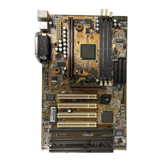
II. FEATURES The ASUS P2B Motherboard ATX Power Connector Slot 1 Intel 440BX AGPset 3 DIMM Sockets T: PS/2 Mouse B: PS/2 Keyboard T: USB Port 1 B: USB Port 2 B: COM 1 T: Parallel B: Serial B: COM 2... -
Page 10: Hardware Setup
III. HARDWARE SETUP Layout of the ASUS P2B Motherboard PWR_FAN TOP: CPU_FAN Mouse PS/2 BOTTOM: Keyboard TOP: USB 1 BOTTOM: USB 2 BUS FREQ Intel 440BX AGPset JTCPU Accelerated Graphics Port Wake-On-LAN Connector PCI Slot 1 Multi-I/O CR2032 3V Lithium Cell... -
Page 11: Hardware Monitor
32 Keyboard Lock Switch Lead (2 pins) 22) SPEAKER (PANEL) p. 32 Speaker Output Connector (4 pins) The onboard hardware monitor uses the address 290H-297H so legacy ISA cards must not use this address otherwise conflicts will occur. ASUS P2B User’s Manual... -
Page 12: Installation Steps
3. Hold components by the edges and try not to touch the IC chips, leads or connectors, or other components. 4. Place components on a grounded antistatic pad or on the bag that came with the component whenever the components are separated from the system. ASUS P2B User’s Manual... -
Page 13: Jumper Settings
<Delete> during bootup and enter BIOS setup to re-enter user preferences. Short small solder points to clear CMOS CLRTC P2B Clear RTC RAM 2. Keyboard Power Up (KBPWR) This allows you to disable or enable the keyboard power up function. Set to Enable if you want to use your keyboard (by pressing <Spacebar>) to power up... - Page 14 112MHz 133MHz 33.4MHz 37.5MHz 41.65MHz 33.3MHz 33.4MHz 37.3MHz 33.3MHz/ 44.3MHz CPU External Clock (BUS) Frequency Selection WARNING! Frequencies above 100MHz exceed the specifications for the on- board Intel Chipset and are not guaranteed to be stable. ASUS P2B User’s Manual...
- Page 15 66MHz [1-2] [1-2] [2-3] [1-2] [1-2] [2-3] [2-3] For updated processor settings, please visit ASUS’ web site (see ASUS CONTACT INFORMATION) NOTES: Overclocking your processor is not recommended. It may result in a slower speed. Voltage Regulator Output Selection (VID) is not needed for the Pentium III/ II/Celeron processor because it sends a VID signal directly to the onboard power controller.
- Page 16 III. HARDWARE SETUP (This page was intentionally left blank.) ASUS P2B User’s Manual...
-
Page 17: System Memory (Dimm)
If your DIMMs are not PC100-compliant, set the CPU bus frequency (FS) to 66MHz for system stability. • ASUS motherboards support SPD (Serial Presence Detect) DIMMs. This is the memory of choice for best performance vs. stability. •... -
Page 18: Dimm Memory Installation Procedures
20 Pins 60 Pins 88 Pins Lock P2B 168-Pin DIMM Memory Sockets FRONT The DIMMs must be 3.3Volt unbuffered SDRAMs. To determine the DIMM type, check the notches on the DIMMs (see figure below). -
Page 19: Central Processing Unit (Cpu)
SECC/SECC2, or a Celeron™ processor packaged in a Single Edge Proces- sor Package (SEPP). An ASUS S370 CPU card can allow Socket 370 processors to be used on any ASUS motherboard with the Slot 1 connector (See ASUS S370 CPU Card in APPENDIX for instructions on using this card). -
Page 20: Installing The Processor
Four Pins and metal clip NOTE: The SEPP heatsink and fan (for Intel Celeron processors) is similar to the SECC2 heatsink and fan except that the clamping design is different. ASUS P2B User’s Manual... - Page 21 II only: The SECC locks should be outward when se- cured so that the lock shows through the retention mechanism’s lock holes. SECC SECC2/SEPP Lock hole Lock hole CPU fan CPU fan cable to cable to fan fan connector connector ASUS P2B User’s Manual...
-
Page 22: Asus Smart Thermal Solutions
III. HARDWARE SETUP ASUS Smart Thermal Solutions ASUS provides two smart solutions to Slot 1 CPU thermal problems: the ASUS Smart Fan or ASUS S-P2FAN and the ASUS P2T-Cable. ASUS S-P2FAN Thermal Cable CPU Fan Cable (2 black wires) (3 colored wires) The optional ASUS Smart Fan or ASUS S-P2FAN is a ®... -
Page 23: Recommended Heatsinks For Slot 1 Processors
The recommended heatsinks for the Slot 1 processors are those with three-pin fans, such as the ASUS Smart Fan, that can be connected to the motherboard’s CPU fan connector. These heatsinks dissipate heat more efficiently and with an optional hard- ware monitor, they can monitor the fan’s RPM and use the alert function with the... -
Page 24: Expansion Cards
(to gain access, double-click the System icon under the Control Panel program). Ensure that no two devices share the same IRQs or your computer will experience problems when those two devices are in use at the same time. ASUS P2B User’s Manual... -
Page 25: Assigning Dma Channels For Isa Cards
Accelerated Graphics Port This motherboard provides an accelerated graphics port (AGP) slot to support a new generation of graphics cards with ultra-high memory bandwidth, such as an ASUS 3D Hardware Accelerator. P2B Accelerated Graphics Port (AGP) -
Page 26: External Connectors
The system will direct IRQ12 to the PS/2 mouse if one is detected. If not de- tected, expansion cards can use IRQ12. See “PS/2 Mouse Control” in BIOS Features Setup of the BIOS SOFTWARE. PS/2 Mouse (6-pin Female) ASUS P2B User’s Manual... - Page 27 (Pin 5 is removed to prevent inserting in the wrong orienta- tion when using ribbon cables with pin 5 plugged). NOTE: Orient the red stripe to Pin 1 Floppy Drive Connector Pin 1 P2B Floppy Disk Drive Connector ASUS P2B User’s Manual...
- Page 28 Primary or Secondary IDE con- nectors will cause the LED to light up. IDELED TIP: If the case-mounted LED does not light, try reversing the 2-pin plug. P2B IDE Activity LED ASUS P2B User’s Manual...
- Page 29 NOTE: The “Rotation” signal is to be used only by a spe- cially designed fan with rotation signal. The Rotations per Minute (RPM) can be monitored using ASUS PC Probe Utility or Intel LDCM Utility. WARNING! The CPU and/or motherboard will overheat if there is no airflow across the CPU and onboard heatsinks.
- Page 30 IRTX FIRRX IRRX For the infrared feature to be available, P2B Infrared Module Connector you must connect the optional Infrared (IrDA) module to the motherboard 12. ATX Power Supply Connector (20-pin ATXPWR) This connector connects to a ATX power supply. The plug from the power sup- ply will only insert in one orientation because of the different hole sizes.
- Page 31 13. Wake-on-LAN Connector (3-pin WOL_CON) The WOL_CON connector powers up the system when a wakeup packet or signal is received from the network through the ASUS PCI-L101 LAN card (see section VII. ASUS LAN Card). IMPORTANT: This feature requires that the WAKE On LAN Power Up Control is set to Enabled (see “Power Management Setup”...
- Page 32 Power LED +5 V MLED PLED Keyboard Lock ExtSMI# KEYLOCK SMI Lead Ground Ground PWR_SW ATX Power +3VSB Speaker Switch* Ground Connector ResetCon Ground Reset SW SPKR Ground Requires an ATX power supply. P2B System Panel Connections ASUS P2B User’s Manual...
-
Page 33: Power Connection Procedures
Shut down the computer? The power supply should turn off after Windows shuts down. NOTE: The message “You can now safely turn off your computer” will not ap- pear when shutting down with ATX power supplies. ASUS P2B User’s Manual... -
Page 34: Bios Setup
4. In DOS mode, type A:\AFLASH <Enter> to run AFLASH. IMPORTANT! If “unknown” is displayed after Flash Memory:, the memory chip is either not programmable or is not supported by the ACPI BIOS and there- fore, cannot be programmed by the Flash Memory Writer utility. ASUS P2B User’s Manual... -
Page 35: Updating Bios Procedures
BIOS revision will solve your problems. Care- less updating can result in your motherboard having more problems! 1. Download an updated ASUS BIOS file from the Internet (WWW or FTP) (see ASUS CONTACT INFORMATION on page 3 for details) and save to the disk you created earlier. -
Page 36: Managing And Updating Your Motherboard's Bios
If the Flash Memory Writer utility was not able to suc- cessfully update a complete BIOS file, your system may not be able to boot up. If this happens, your system will need servicing. ASUS P2B User’s Manual... -
Page 37: Bios Setup
You can also restart by turning the system off and then back on again. But do so only if the first two methods fail. When you invoke Setup, the CMOS SETUP UTILITY main program screen will appear with the following options: ASUS P2B User’s Manual... -
Page 38: Load Defaults
To set the date, highlight the “Date” field and then press either <Page Up>/<Page Down> or <+>/<–> to set the current date. Follow the month, day and year format. Valid values for month, day and year are: Month: (1 to 12), Day: (1 to 31), Year: (up to 2079) ASUS P2B User’s Manual... - Page 39 IDE hard disks; set it to Large for drives over 528MB that do not support LBA. Large type of drive can only be used with MS-DOS and is very uncommon. Most IDE drives over 528MB support the LBA mode. ASUS P2B User’s Manual...
- Page 40 If you are using a VGA or any higher resolution card, choose EGA/VGA. Halt On This field determines which types of errors will cause the system to halt. Choose from All Errors; No Errors; All, But Keyboard, All, But Diskette; and All, But Disk/Key. ASUS P2B User’s Manual...
-
Page 41: Bios Features Setup
Because of conflicts with new operating systems, for example, during installation of new softwares, you may have to set this to Disabled to prevent write errors. ASUS P2B User’s Manual... - Page 42 This field enhances hard disk performance by making multi-sector transfers instead of one sector per transfer. Most IDE drives, except older versions, can utilize this feature. Selections are HDD MAX, Disabled, 2, 4, 8, 16, and 32. ASUS P2B User’s Manual...
- Page 43 The default setting is System, where the system prompts for the User Pass- word every time you start your system. The other option is Setup, where the system goes through its startup routine unless the Setup utility is called, when the system prompts for the Supervisor Password. ASUS P2B User’s Manual...
-
Page 44: Chipset Features Setup
Enabled will allow PCI streaming. Leave on default setting. Host Bus Fast Data Ready (Disabled) Leave on default setting. 16-bit I/O Recovery Time (1 BUSCLK) / 8-bit I/O Recovery Time (1 BUSCLK) Timing for 16-bit and 8-bit ISA cards, respectively. Leave on default setting. ASUS P2B User’s Manual... - Page 45 When Enabled, this field allows you to connect your floppy disk drives to the onboard floppy disk drive connector instead of a separate controller card. If you want to use a different controller card to connect the floppy disk drives, set this field to Disabled. ASUS P2B User’s Manual...
- Page 46 Because each IDE device may have a different Mode timing (0, 1, 2, 3, 4), it is necessary for these to be independent. The default setting of Auto will allow autodetection to ensure optimal performance ASUS P2B User’s Manual...
-
Page 47: Power Management Setup
“Power” will appear in the “Control Panel.” Choose “Advanced” in the Power Management Field. Video Off Option (Suspend -> Off ) This field determines when to activate the video off feature for monitor power management. The settings are Suspend -> Off and Always On. ASUS P2B User’s Manual... - Page 48 4 seconds. Suspend allows the button to have a dual func- tion where pressing less than 4 seconds will place the system in sleep mode. Regard- less of the setting, holding the ATX switch for more than 4 seconds will power off the system. ASUS P2B User’s Manual...
- Page 49 With this feature, you can remotely upload/download data to/from systems during off-peak hours. Set to Enabled to set this feature. IMPORTANT: This feature requires the ASUS PCI-L101 LAN Card and an ATX power supply with at least 720mA +5V standby power.
-
Page 50: Pnp And Pci Setup
IRQ. If you install a legacy ISA card that requires a unique IRQ, and you are not using an ICU, you must set the field for that IRQ to Yes. For example: If you install a legacy ISA card that requires IRQ 10, then set IRQ10 Used By ISA to Yes............................ASUS P2B User’s Manual... - Page 51 If your computer has both PCI and AGP VGA cards, this field allows you to select which of the cards will act as your primary card. The default, PCI/AGP, allows your PCI card to take precedent when detected. AGP/PCI uses the AGP card as your pri- mary card. ASUS P2B User’s Manual...
-
Page 52: Load Bios Defaults
<Enter>. The system displays a confirmation message on the screen. Press <Y> and then <Enter> to confirm. Press <N> and then <Enter> to abort. This feature does not affect the fields on the Standard CMOS Setup screen. ASUS P2B User’s Manual... -
Page 53: Supervisor Password And User Password
If you forgot the password, you can clear the password by erasing the CMOS Real Time Clock (RTC) RAM. The RAM data containing the password information is powered by the onboard button cell battery. To erase the RTC RAM, see the CLRTC jumper in the Jumper Settings section. ASUS P2B User’s Manual... -
Page 54: Ide Hdd Auto Detection
The auto-detection feature can only detect one set of parameters for a particular IDE hard drive. Some IDE drives can use more than one set. This is not a problem if the drive is new and empty. ASUS P2B User’s Manual... -
Page 55: Save & Exit Setup
Select this option to exit the Setup utility without saving the modifications you specify during the current session. To exit without saving, highlight the “Exit Without Sav- ing” option on the main screen and then press <Enter>. ASUS P2B User’s Manual... -
Page 56: Support Software
V. SUPPORT SOFTWARE Desktop Management Interface (DMI) Introducing the ASUS DMI Configuration Utility This motherboard supports DMI within the BIOS level and provides a DMI Configu- ration Utility to maintain the Management Information Format Database (MIFD). DMI is able to auto-detect and record information pertinent to a computer’s system such as the CPU type, CPU speed, and internal/external frequencies, and memory size. -
Page 57: Using The Asus Dmi Configuration Utility
V. SUPPORT SOFTWARE Using the ASUS DMI Configuration Utility NOTE: The following screen displays are provided as examples only and may not reflect the screen contents on your system. Edit DMI (or delete) Use the (left-right) cursors to move the top menu items and the (up-down) cursor to move between the left hand menu items. - Page 58 You can load the BIOS defaults from a MIFD file and can clear all user modified and added data. You must reboot your computer in order for the defaults to be saved back into the Flash BIOS. ASUS P2B User’s Manual...
-
Page 59: Appendix
VI. APPENDIX The ASUS CIDB Chassis Intrusion Sensor Module The optional ASUS CIDB is a module for providing audio alarm and logging when there is an intrusion into the chassis of a computer system. The module detects a chas- sis intrusion by either light striking its photo sensor or by contact when its switch connectors are shorted by chassis-mounted momentary toggle switches. -
Page 60: Setting Up The Asus Cidb
VI. APPENDIX Setting up the ASUS CIDB Enable Disable CR2032 3V JP1: Enable/Disable Lithium Cell the Photo Sensor Buzzer best range +5 volt standby (sensitive) 0 (not sensitive) from power supply CON: Sensitivity adjustment for the photo sensor, (0) is least sensitive... -
Page 61: The Asus S370 Cpu Card
The following picture shows the ASUS S370 CPU card with a plastic retainer at- tached to the edge. The retainer is used to hold the ASUS S370 CPU card in place using the motherboard’s Slot 1 retention mechanism. - Page 62 VI. APPENDIX Setting up the ASUS S370 CPU Voltage Screw Hole Screw Hole Brown Lever ASUS S370 Jumper Settings Setting the CPU voltage is not necessary for current socket 370 processors. If re- quired, your socket 370 processor should have its voltage requirement printed on its surface or documentation.
-
Page 63: Asus Pci-L101 Fast Ethernet Card
Motherboard type Other If you are using the ASUS PCI-L101 on an ASUS motherboard, leave the jumper on its defaut setting of “ASUS.” If you are using another brand of motherboard, set the jumper to “Other.” Connect the Wake on LAN (WOL) output signal to the motherboard’s WOL_CON in order to utilize the wake on LAN feature of the moth-... -
Page 64: Software Driver Support
A: To enable Wake-On-LAN function, your system requires Ethernet LAN adapter card that can activate Wake-On-LAN function, a client with Wake-On-LAN capa- bility, and software such as LDCM Rev. 3.10 or up that can trigger wake-up frame. ASUS P2B User’s Manual... -
Page 65: Glossary
PIO (Programmable I/O) IDE requires that the CPU be involved in IDE access and waiting for mechanical events. Bus master IDE transfers data to/from the memory without interrupting the CPU. Bus master IDE driver and bus master IDE hard disk drives are required to support bus master IDE mode. ASUS P2B User’s Manual... - Page 66 Data (SIMD), which is built into the new Intel Pentium PP/MT (P55C) and Pentium II (Klamath) CPU as well as other x86-compatible microprocessors. The MMX in- structions are designed to accelerate multimedia and communications applications, such as 3D video, 3D sound, video conference. ASUS P2B User’s Manual...
- Page 67 PIO mode, which only uses the rising edge of IDE command signal to transfer data, the DMA/33 uses both rising edge and falling edge. Hence, the data transfer rate is double of the PIO mode 4 or DMA mode 2. (16.6MB/s x2 = 33MB/s). ASUS P2B User’s Manual...
- Page 68 With USB, the traditional complex cables from back panel of your PC can be eliminated. ASUS P2B User’s Manual...
Need help?
Do you have a question about the P2B and is the answer not in the manual?
Questions and answers