Table of Contents
Advertisement
Quick Links
Download this manual
See also:
User Manual
Advertisement
Table of Contents

Related Manuals for Asus P2B Pentium II


Summary of Contents for Asus P2B Pentium II
- Page 1 Pentium II Motherboard ® USER’S MANUAL...
- Page 2 Product warranty or service will not be extended if: (1) the product is repaired, modified or altered, unless such repair, modification of alteration is authorized in writing by ASUS; or (2) the serial number of the product is defaced or missing.
-
Page 3: Asus Contact Information
Email: tsd-usa@asus.com.tw WWW: www.asus.com FTP: ftp.asus.com.tw/pub/ASUS ASUS COMPUTER GmbH Marketing Address: Harkort Str. 25, 40880 Ratingen, BRD, Germany Telephone: 49-2102-445011 Fax: 49-2102-442066 Email: info-ger@asus.com.tw Technical Support Hotline: 49-2102-499712 BBS: 49-2102-448690 Email: tsd-ger@asus.com.tw WWW: www.asuscom.de FTP: ftp.asuscom.de/pub/ASUSCOM ASUS P2B User’s Manual... -
Page 4: Table Of Contents
I. INTRODUCTION How this Manual is Organized ............7 Item Checklist ..................7 II. FEATURES Features of the ASUS P2B Motherboard ..........8 The ASUS P2B Motherboard ............9 III. INSTALLATION Layout of the ASUS P2B Motherboard ..........10 Installation Steps ................12 1. - Page 5 ASUS PCI-SC200 & PCI-SC860 SCSI Cards ......... 59 Setting Up the ASUS PCI-SC200 & PCI-SC860 ......60 Setting the INT Assignment for the ASUS PCI-SC200 ....60 Terminator Requirements for SCSI Devices ....... 60 Terminator Settings for the ASUS PCI-SC860 ......61 Terminator Settings for the ASUS PCI-SC200 ......
-
Page 6: Federal Communications Commission Statement
Canadian Department of Communications Statement This digital apparatus does not exceed the Class B limits for radio noise emissions from digital apparatus set out in the Radio Interference Regulations of the Cana- dian Department of Communications. ASUS P2B User’s Manual... -
Page 7: Introduction
Support Software: Information on the included support software VI. ASUS SCSI Cards: Installation of ASUS SCSI cards (optional) VII. ASUS L101 Card: Installation of the ASUS LAN card (optional) Item Checklist Please check that your package is complete. If you discover damaged or missing items, please contact your retailer. -
Page 8: Features
II. FEATURES Features of the ASUS P2B Motherboard The ASUS P2B is carefully designed for the demanding PC user who wants ad- vanced features processed by the fastest CPU. This motherboard: ® • Versatile Processor Support: Intel Pentium II (233MHz–400MHz) processor. -
Page 9: The Asus P2B Motherboard
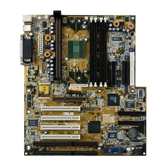
II. FEATURES The ASUS P2B Motherboard ATX Power SEC CPU Socket Connector (PENTIUM II) Intel 440BX AGPset 3 DIMM Sockets T: PS/2 Mouse B: PS/2 Keyboard T: USB Port 1 B: USB Port 2 B: COM 1 T: Parallel B: Serial... -
Page 10: Installation
III. INSTALLATION Layout of the ASUS P2B Motherboard PWR_FAN TOP: CPU_FAN Mouse PS/2 BOTTOM: Keyboard TOP: USB 1 BOTTOM: USB 2 BUS FREQ Intel 440BX AGPset Accelerated Graphics Port Wake on LAN Connector PCI Slot 1 Multi-I/O CR2032 3V Lithium Cell... - Page 11 PCI slots 4&5 share the same interrupt number (INT#) so PCI cards on these two slots must be able to share an INT# or make sure that one of these PCI cards does not use an INT#. ASUS P2B User’s Manual...
-
Page 12: Installation Steps
3. Hold components by the edges and try not to touch the IC chips, leads or connectors, or other components. 4. Place components on a grounded antistatic pad or on the bag that came with the component whenever the components are separated from the system. ASUS P2B User’s Manual... -
Page 13: Jumper Settings
+5VSB lead and new BIOS support. The default is set to Disable because not all computers have the appropriate ATX power supply. Your computer will not function if you set this to Enable and if you do not have the right ATX power supply. KBPWR Disable Enable P2B Keyboard Power ASUS P2B User’s Manual... - Page 14 Overclocking your processor is not recommended. It may result in a slower speed. Voltage Regulator Output Selection (VID) is not needed for the Pentium II processor because it sends a VID signal directly to the onboard power controller. ASUS P2B User’s Manual...
- Page 15 (This page was intentionally left blank..) ASUS P2B User’s Manual...
- Page 16 (This page was intentionally left blank.) ASUS P2B User’s Manual...
-
Page 17: System Memory (Dimm)
BIOS shows EDO or SDRAM memory on bootup screen. • 8 chips/side modules do not support parity, only 9 chips/side modules support parity. • Single sided modules are usually 16, 32, or 64 MB, double sided are usually 32, 64, or 128MB. ASUS P2B User’s Manual... -
Page 18: Dimm Memory Installation Procedures
DIMM slot on the motherboard. You must ask your retailer for the specifications before purchasing. Four clock signals are supported on this motherboard. ASUS P2B User’s Manual... -
Page 19: Central Processing Unit (Cpu)
Heatsink bottom Groove for the Support Top Bar Heatsink Support Base/Top Bar (Items 4-7) Pentium II Processor Heatsink (Item 8) Intel Pentium II Processor in an SEC Cartridge (233-400MHz 256/512KB L2 Cache) CPU (Item 9) ASUS P2B User’s Manual... - Page 20 Then, screw the captive nuts in place. WARNING! Do not overtighten the captive nuts. Doing so could damage your motherboard. Tighten captive nuts to no more than 6±1 inch/pound. Lock holes Captive nut Captive nut ASUS P2B User’s Manual...
- Page 21 With the heatsink facing the motherboard’s chipsets, press the cartridge gently but firmly until it is full inserted. Push lock inward ASUS P2B User’s Manual...
- Page 22 Heatsink support top bar (4) Heatsink support base post Heatsink support base (7) ASUS P2B User’s Manual...
-
Page 23: Aavid Heatsink
“Unlock” to “Lock.” You will not be able to also use the heatsink support top bar because of the fan. The heatsink support top bar will, how- ever, still be included in the package, in case you use a heatsink without a fan. ASUS P2B User’s Manual... -
Page 24: Expansion Cards
System icon under the Control Panel program). Ensure that no two devices share the same IRQs or your computer will experience problems when those two devices are in use at the same time. ASUS P2B User’s Manual... -
Page 25: Assigning Dma Channels For Isa Cards
Accelerated Graphics Port This motherboard provides an accelerated graphics port (AGP) slot to support a new generation of graphics cards with ultra-high memory bandwidth, such as the ASUS AGP-V2740 3D Multimedia Accelerator. ASUS AGP-V2740 P2B Accelerated Graphics Port (AGP) ASUS P2B User’s Manual... -
Page 26: External Connectors
The system will direct IRQ12 to the PS/2 mouse if one is detected. If not de- tected, expansion cards can use IRQ12. See “PS/2 Mouse Control” in BIOS Features Setup of the BIOS SOFTWARE. PS/2 Mouse (6-pin Female) ASUS P2B User’s Manual... - Page 27 (Pin 5 is removed to prevent inserting in the wrong orienta- tion when using ribbon cables with pin 5 plugged). NOTE: Orient the red stripe to Pin 1 Floppy Drive Connector Pin 1 P2B Floppy Disk Drive Connector ASUS P2B User’s Manual...
- Page 28 IDE connector. You may install one operating system on an IDE drive and an- other on a SCSI drive and select the boot disk through BIOS Features Setup. NOTE: Orient the red stripe to PIN 1 PIN 1 Secondary IDE Connector Primary IDE Connector P2B IDE Connectors ASUS P2B User’s Manual...
- Page 29 CPU fan if these pins are incorrectly used. These are not jumpers, do not place jumper caps over these pins. Power Supply Fan CPU Fan Power Chassis Fan Power P2B 12Volt Cooling Fan Power ASUS P2B User’s Manual...
- Page 30 10mAmp on the 5-volt standby lead (5VSB). You may experience difficulty in powering on your system if your power supply cannot support the load. For Wake on LAN support, your ATX power supply must supply at least 720mA. ASUS P2B User’s Manual...
- Page 31 12. Wake-on-LAN Connector (3-pin WOL_CON) The WOL_CON connector powers up the system when a wakeup packet or signal is received from the network through the ASUS PCI-L101 LAN card (see section VII. ASUS LAN Card). IMPORTANT: This feature requires that the WAKE On LAN Power Up Con- trol is set to Enabled (see “Power Management Setup”...
- Page 32 Power LED +5 V MLED PLED Keyboard Lock ExtSMI# KEYLOCK SMI Lead Ground Ground PWR_SW ATX Power +3VSB Speaker Switch* Ground Connector ResetCon Ground Reset SW Ground SPKR Requires an ATX power supply. P2B System Panel Connections ASUS P2B User’s Manual...
-
Page 33: Power Connection Procedures
Shut down the computer?. The system will give three quick beeps after about 30 seconds and then power off after Windows shuts down. NOTE: The message “You can now safely turn off your computer” will not appear when shutting down with ATX power supplies. ASUS P2B User’s Manual... -
Page 34: Bios Software
2Mbit flash ROM. This flash ROM requires PFLASH2.EXE as op- posed to PFLASH.EXE as used by other ASUS motherboards with 1Mbit flash ROM. PFLASH2.EXE - This is the Flash Memory Writer utility that updates the BIOS by uploading a new BIOS file to the 2Mbit programmable flash ROM chip on the moth- erboard. -
Page 35: Advanced Features Menu
This option erases the Plug-and-Play (PnP) configuration record. 2. Update BIOS Including Boot Block and ESCD This option updates the boot block, the baseboard BIOS, and the PnP extended sys- tem configuration data (ESCD) parameter block from a new BIOS file. ASUS P2B User’s Manual... -
Page 36: Managing And Updating Your Motherboard's Bios
BIOS to File.” Enter the “Current BIOS Revision:” for the file name. Updating BIOS Procedures (only when necessary) 1. Download an updated ASUS BIOS file from the Internet (WWW or FTP) or a BBS (Bulletin Board Service) (see ASUS CONTACT INFORMATION on page 3 for details) and save to the disk you created earlier. -
Page 37: Bios Setup
Reset button on the system case. You can also restart by turning the system off and then back on again. But do so only if the first two methods fail. When you invoke Setup, the CMOS SETUP UTILITY main program screen will appear with the following options: ASUS P2B User’s Manual... -
Page 38: Load Defaults
To set the date, highlight the “Date” field and then press either <Page Up>/<Page Down> or <+>/<–> to set the current date. Follow the month, day and year format. Valid values for month, day and year are: Month: (1 to 12), Day: (1 to 31), Year: (up to 2079) ASUS P2B User’s Manual... - Page 39 IDE hard disks; set it to Large for drives over 528MB that do not sup- port LBA. Large type of drive can only be used with MS-DOS and is very uncom- mon. Most IDE drives over 528MB support the LBA mode. ASUS P2B User’s Manual...
- Page 40 If you are using a VGA or any higher resolution card, choose EGA/VGA. Halt On (All Errors) This field determines which types of errors will cause the system to halt. Choose from All Errors; No Errors; All,But Keyboard, All,But Diskette; and All,But Disk/Key. ASUS P2B User’s Manual...
-
Page 41: Bios Features Setup
This setting is recommended because of conflicts with new operating systems. Installation of new operating systems require that you disable this to prevent write errors. ASUS P2B User’s Manual... - Page 42 This field enhances hard disk performance by making multi-sector transfers instead of one sector per transfer. Most IDE drives, except older versions, can utilize this feature. Selections are HDD MAX, Disabled, 2, 4, 8, 16, and 32. ASUS P2B User’s Manual...
- Page 43 8, 10, 12, 15, 20, 24, and 30. Typematic Delay (Msec) (250) This field sets the time interval for displaying the first and second characters. Four delay rate options are available: 250, 500, 750, and 1000. ASUS P2B User’s Manual...
-
Page 44: Chipset Features Setup
Enabled will allow PCI streaming. Leave on default setting. Host Bus Fast Data Ready (Enabled) Leave on default setting. 16-bit I/O Recovery Time (1 BUSCLK) / 8-bit I/O Recovery Time (1 BUSCLK) Timing for 16-bit and 8-bit ISA cards, respectively. Leave on default setting. ASUS P2B User’s Manual... - Page 45 When Enabled, this field allows you to connect your floppy disk drives to the onboard floppy disk drive connector instead of a separate controller card. If you want to use a different controller card to connect the floppy disk drives, set this field to Disabled. ASUS P2B User’s Manual...
- Page 46 Because each IDE device may have a different Mode timing (0, 1, 2, 3, 4), it is necessary for these to be independent. The default setting of Auto will allow autodetection to ensure optimal performance ASUS P2B User’s Manual...
-
Page 47: Power Management Setup
Power Management Field. Video Off Option (Suspend -> Off ) This field determines when to activate the video off feature for monitor power manage- ment. The settings are Suspend -> Off and Always On. ASUS P2B User’s Manual... - Page 48 4 seconds will place the system in sleep mode. No Function disables the ATX switch function when the button is pressed under 4 seconds. Regardless of the setting, holding the ATX switch for more than 4 seconds will power off the system. ASUS P2B User’s Manual...
- Page 49 With this feature, you can remotely upload/download data to/from systems during off-peak hours. Set to Enabled to set this feature. IMPORTANT: This feature requires the ASUS PCI-L101 LAN Card (see VII. ASUS LAN Card) and an ATX power supply with at least 720mA +5V standby power.
-
Page 50: Pnp And Pci Setup
ICU, you must set the field for that IRQ to Yes. For example: If you install a legacy ISA card that requires IRQ 10, then set IRQ10 Used By ISA to Yes............................ASUS P2B User’s Manual... - Page 51 Enabled reserves an IRQ# for the USB to work, Disabled does not allow the USB to have an IRQ# and therefore prevents the USB from functioning. If you are not using any USB devices, you may set this feature to Disabled to save an extra IRQ# for expansion cards. ASUS P2B User’s Manual...
-
Page 52: Load Bios Defaults
<Enter>. The system displays a confirmation message on the screen. Press <Y> and then <Enter> to confirm. Press <N> and then <Enter> to abort. This feature does not affect the fields on the Standard CMOS Setup screen. ASUS P2B User’s Manual... -
Page 53: Supervisor Password And User Password
<Enter> instead of entering a new password when the “Enter Password” prompt appears. A message confirms the password has been disabled. NOTE: If you forget the password, see CMOS RAM in section III for procedures on clearing the CMOS. ASUS P2B User’s Manual... -
Page 54: Ide Hdd Auto Detection
The auto-detection feature can only detect one set of parameters for a particular IDE hard drive. Some IDE drives can use more than one set. This is not a problem if the drive is new and empty. ASUS P2B User’s Manual... -
Page 55: Save & Exit Setup
Select this option to exit the Setup utility without saving the modifications you specify during the current session. To exit without saving, highlight the “Exit Without Sav- ing” option on the main screen and then press <Enter>. ASUS P2B User’s Manual... -
Page 56: Desktop Management Desktop Management Interface (Dmi)
V. DESKTOP MANAGEMENT Desktop Management Interface (DMI) Introducing the ASUS DMI Configuration Utility This motherboard supports DMI within the BIOS level and provides a DMI Con- figuration Utility to maintain the Management Information Format Database (MIFD). DMI is able to auto-detect and record information pertinent to a computer’s system such as the CPU type, CPU speed, and internal/external frequencies, and memory size. -
Page 57: Using The Asus Dmi Configuration Utility
V. DESKTOP MANAGEMENT Using the ASUS DMI Configuration Utility Edit DMI (or delete) Use the ←→ (left-right) cursors to move the top menu items and the ↑↓ (up-down) cursor to move between the left hand menu items. The bottom of the screen will show the available keys for each screen. - Page 58 You can load the BIOS defaults from a MIFD file and can clear all user modified and added data. You must reboot your computer in order for the defaults to be saved back into the Flash BIOS. ASUS P2B User’s Manual...
-
Page 59: Asus Pci Scsi Cards
SCO UNIX floppy disk. Windows 95 support is also available using the device drivers included within the Windows software. The ASUS PCI-SC200 and ASUS PCI-SC860 are Plug and Play adapters that are auto detected by BIOS and current operating systems that support Plug and Play features. -
Page 60: Setting Up The Asus Pci-Sc200 & Pci-Sc860
VI. ASUS PCI SCSI Cards Setting Up the ASUS PCI-SC200 & PCI-SC860 There are two jumper settings you may need to make on the ASUS PCI-SC200 to set it up. One setting assigns the PCI INT interrupt, the other sets the card’s termination. -
Page 61: Terminator Settings For The Asus Pci-Sc860
Not Terminated Terminator Setting (Terminated / Not Terminated) Decide whether or not you need to terminate the ASUS PCI-SC200 based on its position in the SCSI chain. Only the devices at each end of the chain need to be terminated. If you have only internal or only external devices connected to the ASUS PCI-SC200, then you must terminate the ASUS PCI-SC200. -
Page 62: Scsi Id Numbers For Scsi Devices
SCSI identification number that is not in use by any other SCSI device. There are eight possible ID numbers, 0 through 7. The ASUS PCI-SC200 and ASUS PCI-SC860 cards have fixed SCSI IDs of 7. The SCSI ID serves two purposes: •... -
Page 63: Asus Lan Card
Motherboard type Other If you are using the ASUS PCI-L101 on an ASUS motherboard, leave the jumper on its defaut setting of “ASUS.” If you are using another brand of motherboard, set the jumper to “Other.” Connect the Wake on LAN (WOL) output signal to the motherboard’s WOL_CON in order to utilize the wake on LAN feature of the moth-... -
Page 64: Features
VII. ASUS LAN Card Features • Intel 82558 Ethernet LAN Controller (Fully integrated 10BASE-T/100BASE-TX) • Wake-On-LAN Remote Control Function Supported • PCI Bus Master Complies to PCI Local Bus Rev. 2.1 specifications • Consists of MAC & PHY (10/100Mbps) interfaces •...
Need help?
Do you have a question about the P2B Pentium II and is the answer not in the manual?
Questions and answers