
Related Manuals for HP 336045-B21 - Server Console Switch KVM


Summary of Contents for HP 336045-B21 - Server Console Switch KVM
-
Page 1: User Guide
HP IP and Server Console Switches G2 User Guide Part Number 585313-001 September 2009 (First Edition) - Page 2 Microsoft and Windows are U.S. registered trademarks of Microsoft Corporation. Intel is a trademark or registered trademark of Intel Corporation or its subsidiaries in the United States and other countries. AMD and Opteron are trademarks of Advanced Micro Devices, Inc. Bluetooth is a trademark owned by its proprietor and used by Hewlett-Packard Company under license. Intended audience This document is for the person who installs racks and rack products.
-
Page 3: Table Of Contents
Contents Product features ..........................7 Overview of features ..........................7 KVM switching capabilities......................... 7 True serial capabilities ..........................8 Local and remote user interfaces ......................... 8 Virtual media capabilities ........................... 8 Smart card capabilities ..........................8 Component identification ....................... 9 HP Server G2 Console Switch components .................... - Page 4 Using the user interfaces .......................... 32 Target devices ............................32 Appliance tools............................33 Upgrading the console switch firmware .................... 34 Saving the console switch configuration or user database ..............35 Restoring the console switch configuration or user database..............35 Viewing system information ........................36 System alerts..........................
- Page 5 Using local Virtual Media ......................... 64 Using Virtual Media in a two-level cascade configuration ................64 Using smart cards ........................66 Smart card overview..........................66 Using a smart card through Video Session Viewer ..................66 LDAP ............................67 LDAP overview............................67 LDAP configuration ..........................
- Page 6 Index............................85...
-
Page 7: Product Features
Product features Overview of features HP offers two types of console switches that provide flexible, centralized control of data center servers and infrastructure appliances: • HP IP Console Switch G2 • HP Server Console Switch G2 NOTE: Unless otherwise specified, console switch refers to both the HP IP Console Switch and the HP Server Console Switch. -
Page 8: True Serial Capabilities
True serial capabilities The console switch supports the HP Serial G2 Adapter, which provides true serial capabilities. You can directly launch an SSH or Telnet session or launch a serial viewer from the local console UI or remote OBWI to establish a serial console session. Local and remote user interfaces To configure and manage your console switch, you can use either the local console UI or the remote OBWI. -
Page 9: Component Identification
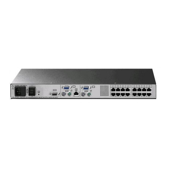
Component identification HP Server G2 Console Switch components Item Description Power supply status indicator LEDs LAN connector Tiering chain port RJ-45 serial setup port Console A VGA connector Console A USB ports Console B VGA connector Console B USB ports Interface adapter ports (1-16) Interface adapter ports (17-32) Power connectors A &... -
Page 10: Hp Ip G2 Console Switch Components
HP IP G2 Console Switch components 1x1Ex8 Item Description Power supply status indicator LEDs LAN 1 LAN 2 S1, S2, and S3 (reserved for future use) Tiering chain port RJ-45 serial setup port Local console VGA Local console USB ports Interface adapter ports (1-4) Interface adapter ports (5-8) Power connectors A &... -
Page 11: Interface Adapters
Item Description RJ-45 serial setup port Local console VGA Local console USB ports Interface adapter ports (1-16) Interface adapter ports (17-32) Power connectors A & B Interface adapters Interface adapters that support Virtual Media have two LEDs on the front of the RJ-45 connector. Item Description When lit, this LED indicates that the interface adapter has power... - Page 12 USB 2.0 interface adapter with Virtual Media Item Description Video connector RJ-45 connector USB connector PS2 interface adapter with Virtual Media Item Description Video connector RJ-45 connector USB connector (for Virtual Media only) Mouse connector Keyboard connector Component identification 12...
- Page 13 Serial interface adapter G2 Item Description RJ-45 serial connector (to RJ-45/DB9 adapter or to a Cisco appliance) Power connector (mate to USB power connector or power supply) RJ-45 connector (for CAT5 to switch) USB interface adapter with Virtual Media and CAC Item Description Video connector...
- Page 14 PS2 interface adapter with Virtual Media and CAC Item Description Video connector Mouse connector Keyboard connector USB connector (for Virtual Media only) RJ-45 connector To determine which interface adapter you should use, see Selecting an interface adapter (on page 23). Component identification 14...
-
Page 15: Installing The Console Switch
Installing the console switch Installation overview This product ships with rack-mounting brackets for easy integration into the rack. Before installing this product and other components in the rack cabinet (if they are not already installed), stabilize the rack in a permanent location. -
Page 16: Required Items Not Included
Required items not included • Interface adapters ("Installing the interface adapter" on page 23) One interface adapter is needed for each server or device. Serial HP BladeSystem • UTP CAT 5 or better cable • Cage nuts and M6 screws (included with your original rack hardware kit) Required tools The following tools are required for some procedures: •... - Page 17 Attach the long 1U brackets to the console switch using four of the screws you removed. Discard the two remaining screws. If not already installed, install a cage nut behind each rear rail. Slide the console switch into the rear of the 1U product. Secure the console switch to the rails using two M-6 screws, one on each side.
-
Page 18: Performing A Cantilever-Mount Installation
Performing a cantilever-mount installation Remove the six screws, three on each side, from the console switch. Attach the long 1U brackets to the console switch using four of the screws you removed. Discard the two remaining screws. Install up to six cage nuts. Secure the console switch to the rails using the appropriate number of M-6 screws. - Page 19 Attach the side-mounting brackets to the console switch using four of the screws you removed. Discard the two remaining screws. Slide the side-mounting bracket tabs into the U locations on each side of the rack. Installing the console switch 19...
-
Page 20: Connecting The Console Switch
Install four cage nuts into the side-mounting bracket U locations. Secure the console switch to the rails, using four M-6 screws, two on each side. NOTE: Some racks enable you to use four sheet metal screws in place of M-6 screws and cage nuts. -
Page 21: Verifying Connections
Unplug the power cord from the power supply to disconnect power to the equipment. • Do not route the power cord where it can be walked on or pinched by items placed • against it. Pay particular attention to the plug, electrical outlet, and the point where the cord extends from the storage system. -
Page 22: Rear Panel Ethernet Connection Leds
• Blinks Morse code SOS—The power supply whose indicator LED is not blinking does not have power or has failed. • Blinks consistently—A firmware upgrade is in process. Rear panel Ethernet connection LEDs The rear panel of the switch features two LEDs that indicate the Ethernet connection for LAN1 and two LEDs that indicate the Ethernet connection for LAN2. -
Page 23: Installing The Interface Adapter
Installing the interface adapter Interface adapter overview An interface adapter is required for the console switch system to function properly. However, an interface adapter is not included in the console switch kit. The interface adapter is connected to a console switch using a CAT5 cable. -
Page 24: Connecting The Interface Adapter
Interface Type Part number Prime function Optimal use adapter serial console managed devices *Not supported for use with ProLiant servers. Connecting the interface adapter NOTE: If you use the HP USB with Virtual Media interface adapter to connect to your ProLiant server, test the functionality of your keyboard and mouse at the BIOS level before you load your operating system. -
Page 25: Cascading Console Switches
Cascading console switches Cascading console switches overview The G2 console switches support two levels of cascading or tiering devices. You can cascade multiple console switches to increase the number of devices available from a single access point. When cascading console switches with Virtual Media, verify the following: •... -
Page 26: Cascading Two Hp Server Console Switches G2
Primary console switch Secondary console switch Supported features* HP Server Console Switch G2 with HP IP Console Switch G2 with Virtual Virtual Media Virtual Media Media Smart Card HP Server Console Switch G2 with HP Server Console Switch G2 with Virtual Media Virtual Media Virtual Media... -
Page 27: Example Of An Hp Server Console Switch G2 Cascade Configuration
Example of an HP Server Console Switch G2 cascade configuration Item Description Servers Interface adapters (USB 2.0 interface adapter with Virtual Media or PS2 interface adapter with Virtual Media) UTP CAT5 cable Local console KVM cables Local console monitor Primary console switch Servers Interface adapters (USB 2.0 interface adapter with Virtual Media or PS2 interface adapter with Virtual... -
Page 28: Cascading An Hp Server Console Switch G2 Under An Hp Ip Console Switch G2
Item Description UTP CAT5 cable UTP CAT5 cable (tiering cable) Secondary console switch Cascading an HP Server Console Switch G2 under an HP IP Console Switch G2 The following figure shows an HP Server Console Switch G2 cascaded to an HP IP Console Switch G2. Do not use interface adapters to cascade console switches. - Page 29 To cascade the console switches: Connect a UTP CAT5 or better cable to the interface adapter port on the console switch. Connect the other end of the cable to the tiering port on the secondary console switch. Cascading console switches 29...
-
Page 30: Configuring The Console Switch
Configuring the console switch The user interfaces To configure and manage your console switch, you can use either the local console UI or the remote OBWI. The two user interfaces share a similar look and feel for optimal user experience. The information in this chapter applies to both user interfaces. - Page 31 Operating system Browser: Browser: Microsoft® Internet Mozilla Firefox® version Explorer® version 6.0 2.0 and later SP1 and later Windows Server® 2003 Standard, Enterprise of Web Edition Windows XP Home Edition or Professional Windows Vista® Red Hat® Enterprise Linux 3, 4, and 5 Sun®...
-
Page 32: Using The User Interfaces
the KVM switch through the firewall internal interface. For specific port forwarding instructions, see your firewall documentation. Using the user interfaces After you have successfully logged into either the local console UI or the remote OBWI, the user interface appears. Callou Component Description... -
Page 33: Appliance Tools
Select the name of the interface adapter you want to view. The Unit Overview page appears. The following properties appear: Device name—Edit to match the name of the interface adapter it is connected to Type—Lists the type of interface adapter EID—Lists the identification number of the interface adapter Sessions—Enables you launch an interface adapter session From the side navigation bar, select Connections to view the device connection path. -
Page 34: Upgrading The Console Switch Firmware
• Save Application Trap MB Upgrading the console switch firmware HP recommends updating your console switch with the latest firmware available. CAUTION: Do not disconnect an interface adapter during a firmware upgrade or power cycling. The interface adapter becomes inoperable and must be returned to the factory for repair. -
Page 35: Saving The Console Switch Configuration Or User Database
Select one of the following options to load the firmware file: Filesystem—Select Browse to specify the location of the firmware upgrade file. TFTP—Enter the server IP address and firmware file to load. FTP—Enter the server IP address and firmware file to load. A username and password is required for authentication. -
Page 36: Viewing System Information
Select either Restore Appliance Configuration or Restore Appliance User Database. The Restore Appliance Configuration or Restore Appliance User Database page appears. Select the type and location of the file you want to restore: Filesystem TFTP HTTP Enter the Decryption Password. The file is uploaded to the console switch. Reboot the console switch ("Appliance tools"... -
Page 37: Network Settings
Network settings Only Administrators can make changes to the network settings. All other users can view network settings, but cannot make changes. General network settings To configure General network settings: Select Unit View>Appliance>Appliance Settings>Network>General. The Appliance General Network Settings page appears. NOTE: If you change the LAN speed, you must reboot the console switch. -
Page 38: Ntp Settings
Select the DNS Assignment Mode: Manual BOOTP DHCPv6 Enter the DNS server addresses in the Primary, Secondary, and Tertiary fields. NTP settings To configure NTP settings: Select Unit View>Appliance>Appliance Settings>NTP. The NTP page appears. To enable NTP, select the Enable NTP checkbox. Enter the name/address of the NTP servers in the NTP Server 1 and NTP Server 2 fields. -
Page 39: Enabling Snmp Traps
Select Unit View>Appliance>Appliance Settings>SNMP. The SNMP page appears. To enable SNMP, select the Enable SNMP checkbox. Enter the appropriate information in the following fields: Name Description Contact NOTE: The community name fields can be up to 64 characters in length. If SNMP is enabled, these fields cannot be left blank. - Page 40 Select Unit View>Appliance>Appliance Settings>Auditing>Events. The Events page appears. Select the checkbox for each SNMP trap you want sent to the management station. Select Unit View>Appliance>Appliance Settings>Auditing>Destinations. The Event Destination page appears. Configuring the console switch 40...
-
Page 41: Ports
Enter up to four addresses of the management stations where you want the SNMP traps and Syslog information sent. Ports You can view and edit the information for the following console switch ports: • Interface adapters • Cascade devices • Local console port UI Interface adapter ports To view the port location of each interface adapter attached to the console switch:... -
Page 42: Cascade Devices Ports
Select Unit View>Appliance>Appliance Settings>Ports>IAs. The Appliance IAs page appears. Select the checkbox next to the interface adapter you want to upgrade. Select Upgrade. Interface adapter serial session settings To configure the serial session settings of an individual interface adapter: Select Unit View>Appliance>Appliance Settings>Ports>IAs. The Appliance IAs page appears. Select the interface adapter you want to configure, by clicking the name under the EID column. -
Page 43: Configuring Sessions
Select Unit View>Appliance>Appliance Settings>Ports>Local Port UI. The Local Port UI Settings page appears. In the Invoke Local Port UI, select the checkbox of one or more methods of launching a local console UI session. Configure the following parameters: Local port user settings Scan mode Keyboard Setup port settings... - Page 44 Configure the following parameters: In the Enable Inactivity Timeout checkbox, select or clear the checkbox. In the Inactivity Timeout field, select the number of minutes of inactive time you want to pass before the session closes. In the Login Timeouts field, select the number of seconds of inactive time you want to allow before failing an authentication request.
-
Page 45: Configuring Kvm Session Settings
Configuring KVM Session settings Select Unit View> Appliance> Appliance Settings> Sessions> KVM. The KVM Session Settings page appears. Configure the following parameters: Select an Encryption Level for your keyboard and mouse. Select an Encryption Level for your video. Select the language of the keyboard you are using. Select the monitor resolution you are using: either Standard or Widescreen. - Page 46 Select Unit View> Appliance> Appliance Settings> Sessions> Virtual Media. The Appliance Virtual Media Session Settings page appears. Configure the Session Settings: Locked sessions—Locks the Virtual Media session to the KVM session. If you enable the Locked session setting, your Virtual Media session is disconnected if the KVM session is disconnected. Reserved—Ensures that a Virtual Media connection can only be accessed by the user that established the session.
-
Page 47: Configuring Serial Session Settings
Configuring Serial Session settings Select Unit View> Appliance> Appliance Settings> Sessions> Serial. The Appliance Serial Session Settings page appears. Select the Telnet Access Enabled checkbox, if you want to enable Telnet. SSH communication is enabled by default. To connect to the console switch using SSH, you must have a password assigned to the user account, as required by SSH. -
Page 48: Local User Accounts
Operation Access level: Access level: Appliance Users Administrator accounts Change your password Access target device Yes* *Users can access a target device as long as the administrator has not reserved the device. For more information, see Local virtual media settings. Local user accounts To configure local user accounts: Select Unit View>Appliance>Appliance Settings>User Accounts>Local. -
Page 49: Mergepoint Access Settings
Select Add. The Add Appliance Local User Account page appears. Enter the Username and Password of the new user. Select the Access Level. Highlight all available target devices the user is assigned to, and then select Add. To edit a user: Select the checkbox next to the user you want to edit. -
Page 50: Configuring Ldap
Select Unit View>Appliance>Appliance Settings>User Accounts>MergePoint Access. The Appliance MergePoint Access Settings page appears. Configure MergePoint Access settings. Configuring LDAP NOTE: Unless otherwise specified, use the LDAP default values, unless Active Directory has been reconfigured. Modifying the default values might cause LDAP authentication server communication errors. -
Page 51: Ldap Search
Select Unit View>Appliance>Appliance Settings>User Accounts>LDAP. The Appliance LDAP Overview page appears. Configure the LDAP authentication priority by selecting either Use Local Authentication or Use LDAP Authentication. NOTE: The secondary LDAP server is optional. Configure the LDAP servers information: Address—Specifies the host names or IP addresses of the primary and secondary LDAP servers. Port—Specifies the UDP port numbers that communicate with the LDAP servers. -
Page 52: Ldap Query
Select Unit View>Appliance>Appliance Settings>User Accounts>LDAP>Search. The Appliance LDAP Search page appears. NOTE: The LDAP Search and Query parameters can only be configured if LDAP Authentication is enabled on the LDAP Overview ("Configuring LDAP" on page 50) page. Configure the Search parameters: Search DN—Defines the administrator-level user that the target device uses to log into the directory service. - Page 53 Select Unit View>Appliance>Appliance Settings>User Accounts>LDAP>Query. The Appliance LDAP Query page appears. NOTE: The LDAP Search and Query parameters can only be configured if LDAP Authentication is enabled on the LDAP Overview ("Configuring LDAP" on page 50) page. Configure the Query Mode parameters for: Appliance—Used to authenticate administrators and users attempting to access the console switch itself.
-
Page 54: Override Admin
Group Container—Specifies the OU created in Active Directory by the administrator as the location for group objects. Group objects can contain users, computers, contacts, and other groups, each assigned with a certain access level. Group Container Mask—Defines the object type of the Group Container, normally an OU. The default value is ou=%1. -
Page 55: Local Sessions
• Owner—The user logged in and activating the session. • Remote host—The IP address of the computer where the active session is running. • Duration—Amount of time the device has been in active session. • Type—The type of session (KVM or Serial) To launch a new active session: NOTE: Java™... -
Page 56: Disconnecting An Active Session
Select Scan. To configure the scan time interval, see Local console UI settings (on page 42). Disconnecting an active session Select Unit View>Active Sessions. The Appliance Sessions page appears. Select the checkbox next to the target device session you want to close. Select Disconnect. -
Page 57: Video Session Viewer
Video Session Viewer The Video Session Viewer overview The Video Session Viewer is used to conduct a KVM session with target devices attached to a console switch using the remote OBWI. When you connect to a target device using the Video Session Viewer, the device desktop appears in a separate window containing both the local and target device cursors. - Page 58 The following view of the Video Session Viewer is in normal window mode. Item Description Title bar—Displays the name of the server you are viewing To access the menu bar, place your cursor in the middle bottom of the title bar. Menu bar—Enables you to access features Server desktop—Enables you to interact with the server through this desktop...
-
Page 59: Changing The Toolbar
Changing the toolbar You can adjust the amount of time that passes before the toolbar hides in the Video Session Viewer window when it is not locked by thumbtack. Choose one of the following options: From the Video Viewer window menu, select Tools>Session Options. Select the Session Options button. -
Page 60: Window Size
Manual scaling—A menu of supported image scaling resolutions appears. • Change the color depth of the session image. Window size Each Video Viewer window can be set to a different resolution. The default resolution is 1024 x 768. If autoscaling is enabled, the remote OBWI automatically adjusts the display if the window size changes during a session. -
Page 61: Using Virtual Media
Using Virtual Media Virtual Media overview In this section on Virtual Media, the remote console for HP Server Console Switches with Virtual Media is only available if the console switch is tiered underneath an HP IP Console Switch with Virtual Media. The console switch enables you to connect shared media to a server using a USB connection. -
Page 62: Virtual Media Resources
HP recommends using the PS2 interface adapter with Virtual Media for AMD Opteron™-based HP ProLiant servers and Red Hat Enterprise Linux 4 (before Update 5), as well as older and third-party servers. Virtual Media resources Virtual Media resources cannot be shared between a local console and a remote console. For example, a remote user using the HP IP Console Viewer cannot use a Virtual Media resource attached to the local console USB hub. -
Page 63: Virtual Media Dialog Box
on page 45) to reserve sessions, allowing only User A to access that channel with a KVM session. By using the reserved option in a tiered environment, only User A can access the lower switch and the KVM channel between the upper switch and lower switch. If User B is allowed to access the session, User B can control the media used in the virtual media session. -
Page 64: Using Local Virtual Media
Using local Virtual Media For local Virtual Media to work properly, you must have an HP Server Console Switch with Virtual Media or an HP IP Console Switch with Virtual Media as the console switch. You must also have an interface adapter with Virtual Media connecting each server to the console switch. - Page 65 For more information on cascading, see Cascading console switches (on page 25). Item Description Local user USB media device Console switch (HP Server Console Switch with Virtual Media or HP IP Console Switch with Virtual Media) Secondary console switch (HP Server Console Switch with Virtual Media) USB 2.0 interface adapter with Virtual Media PS2 interface adapter with Virtual Media...
-
Page 66: Using Smart Cards
Using smart cards Smart card overview You can use a smart card, also referred to as a CAC, with your console switch when two-factor authentication is required. NOTE: To use a smart card reader with a target device, you must first connect the target device to a console switch using a smart card capable interface adapter. -
Page 67: Ldap
LDAP LDAP overview LDAP is a vendor-independent protocol standard used for accessing, querying, and updating a directory using TCP/IP. Based on the X.500 Directory Services model, LDAP is a global directory structure that supports strong security features, including authentication, privacy, and integrity. If individual user accounts are stored on an LDAP-enabled directory service, such as Active Directory, you can use the directory service to authenticate users. -
Page 68: Console Switch Serial Management
Console switch serial management Establishing LAN connections NOTE: Although 10Base-T Ethernet can be used, HP recommends a dedicated, switched 100Base-T or 1000Base-T network for improved performance. Connect the network cable from the LAN port on the rear panel of the console switch to an Ethernet switch, and power on the console switch. -
Page 69: Using The Main Menu
NOTE: The following example uses Red Hat Linux 3.0. For more information, refer to your Linux operating system Help or documentation. IMPORTANT: Minicom is a utility that is loaded during the installation of Linux. However, if you do not select the option to install the Linux Utilities during the operating system installation, you cannot use Minicom without downloading the Minicom X.X.i386.rpm file from the Red Hat website. -
Page 70: Network Configuration
To access the Main Menu: Establish a terminal session, and then press Enter. The Main Menu appears. Network Configuration The Network Configuration option enables you to set the network speed and either IPv4 or IPv6 settings. Enable Debug Messages The Enable Debug Messages option enables you to debug the system. Select yes to debug the system. Reset Appliance The Reset Appliance option reboots the server console switch. -
Page 71: Configuring The Console Switch Nic
Configuring the console switch NIC Establish a terminal session and then press the Enter key. The Main Menu appears. Select Option 1—Network Configuration. The Network Configuration Menu appears. Select Option 1—Network Speed to set the network speed. When possible, set the connection manually without relying on the auto negotiate feature. -
Page 72: Upgrading The Firmware
Upgrading the firmware Upgrading the firmware The console switch upgrade feature enables you to upgrade the console switch and interface adapters with the latest available firmware through the local UI or remote OBWI. For more information, see Upgrading the console switch firmware (on page 34) or Upgrading the interface adapter firmware (on page 41). -
Page 73: Verifying Tftp For Linux Operating Systems
In the Service Configuration menu, verify that the xinetd checkbox is selected to start at boot. -or- If the checkbox is not selected, select the box and click Save. Find TFTP in the list of services and highlight it. Select the checkbox to start TFTP at boot, and then click Save. Verifying TFTP for Linux operating systems NOTE: The following example uses Red Hat Linux 3.0. -
Page 74: Troubleshooting
Troubleshooting Console switch troubleshooting Problem Troubleshooting The console switch is Determine whether the console switch has power. not working properly. Determine if all the cables are properly connected. The console switch Reboot the console switch again by removing the power cable and then plugging it hangs after reboot. -
Page 75: Connection Length Table
Problem Troubleshooting under the Linux shell. adapter is connected. Using the numeric At a shell prompt, enter init q, or reboot the system. keypad with the vi text editor causes function characters to appear rather than numbers. Virtual Media is not Be sure that you are using the following: working properly. -
Page 76: Frequently Asked Questions
Frequently asked questions Console switch frequently asked questions Question Answer Are the interface adapters hot-pluggable? Yes, they are hot-pluggable to the console switch. Using PS2 connections to servers might not be hot-pluggable. Are the keyboard, monitor, and mouse connections on the console switch hot- pluggable? Are the server connections on the console switch hot-pluggable? -
Page 77: Technical Support
Technical support Before you contact HP Be sure to have the following information available before you call HP: • Technical support registration number (if applicable) • Product serial number • Product model name and number • Product identification number • Applicable error messages •... -
Page 78: Regulatory Compliance Notices
Regulatory compliance notices Regulatory compliance identification numbers For the purpose of regulatory compliance certifications and identification, this product has been assigned a unique regulatory model number. The regulatory model number can be found on the product nameplate label, along with all required approval markings and information. When requesting compliance information for this product, always refer to this regulatory model number. -
Page 79: Modifications
Machinery Directive 98/37/EEC Compliance with these directives implies conformity to applicable harmonized European standards (European Norms) which are listed on the EU Declaration of Conformity issued by Hewlett-Packard for this product or product family. This compliance is indicated by the following conformity marking placed on the product:... -
Page 80: Disposal Of Waste Equipment By Users In Private Households In The European Union
This marking is valid for EU non-harmonized Telecom products. *Notified body number (used only if applicable—refer to the product label) Hewlett-Packard GmbH, HQ-TRE, Herrenberger Strasse 140, 71034 Boeblingen, Germany The official EU CE declaration of conformity for this device can be found on the HP website (http://www.hp.com/go/certificates). -
Page 81: Japanese Notice
Japanese notice Korean class A notice Power cord statement for Japan Regulatory compliance notices 81... -
Page 82: Acronyms And Abbreviations
Acronyms and abbreviations alternating current BIOS Basic Input/Output System BOOTP Bootstrap Protocol Common Access Card cyclic redundant checks electronic identification number file transfer protocol Generation 2 GNOME GNU Network Object Model Environment HP SIM HP Systems Insight Manager interface adapter identification Acronyms and abbreviations 82... - Page 83 Internet Protocol keyboard, video, and mouse local-area network LDAP Lightweight Directory Access Protocol light-emitting diode network interface controller OBWI on-board Web interface on-screen display peripheral component interface Red Hat Package Manager Systems Insight Manager SLES SUSE Linux Enterprise Server Secure Shell Transmission Control Protocol Acronyms and abbreviations 83...
- Page 84 TFTP Trivial File Transfer Protocol user interface universal serial bus unshielded twisted pair video graphics array Acronyms and abbreviations 84...
- Page 85 Index console switch, configuration 30 console switch, connecting 20 console switch, installing 15 activating Scan mode 55 console switch, rack mounting 15 Active session, disconnecting 56 console switch, serial management 68 Active sessions 54 console switch, side-mount 18 alerts 36 console switch, standard mount 16 appliance connections 54 console switches, cascading 25...
- Page 86 installation overview 15 modifications, FCC notice 79 installation, cantilever mount 18 installation, side mount 18 installation, standard-mount 16 network settings 37 installing the console switch 15 network settings, DNS 37 installing the interface adapter 23 network settings, general 37 interface adapter 23 network settings, NTP 38 interface adapter ports 41, 42 network settings, SNMP 38...
- Page 87 serial management, reset appliance 70 Video Session Viewer, overview 57 server console switch components 9 Video Session Viewer, session time-out 59 session settings, General 43 Video Session Viewer, smart cards 66 session settings, KVM 45 Video Session Viewer, tasks 60 session settings, serial 47 Video Session Viewer, toolbar 59 session settings, virtual media 45...
Need help?
Do you have a question about the 336045-B21 - Server Console Switch KVM and is the answer not in the manual?
Questions and answers