
Related Manuals for Hitachi NT65MA3 - 2-1/2 Angled Finish Nailer


Summary of Contents for Hitachi NT65MA3 - 2-1/2 Angled Finish Nailer
- Page 1 MODEL NT 65MA3 Hitachi Power Tools TECHNICAL DATA FINISH NAILER NT 65MA3 SERVICE MANUAL LIST No. E036 Sep. 2006 SPECIFICATIONS AND PARTS ARE SUBJECT TO CHANGE FOR IMPROVEMENT...
- Page 2 REMARK: Throughout this TECHNICAL DATA AND SERVICE MANUAL, a symbol(s) is(are) used in the place of company name(s) and model name(s) of our competitor(s). The symbol(s) utilized here is(are) as follows: Competitors Symbols Utilized Company Name Model Name PORTER CABLE DA250B BOSTITCH N62FNK-2...
-
Page 3: Table Of Contents
CONTENTS Page 1. PRODUCT NAME ........................... 1 2. MARKETING OBJECTIVE ......................1 3. APPLICATIONS ..........................1 4. SELLING POINTS .......................... 1 5. SPECIFICATIONS .......................... 2 5-1. Specifications ..........................2 5-2. Explanation of the Nailing Operation ....................3 5-3. Nail Selection ..........................4 5-4. -
Page 4: Product Name
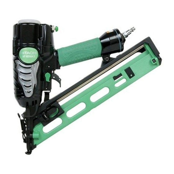
1. PRODUCT NAME Hitachi 2-1/2" Finish Nailer, Model NT 65MA3 2. MARKETING OBJECTIVE The new Model NT 65MA3 finish nailer is a minor-changed version of the current Model NT 65MA2. Primary differences from the Model NT 65MA2 are described below. -
Page 5: Specifications
5. SPECIFICATIONS 5-1. Specifications Model NT 65MA3 Driving system Reciprocating piston type Operating pressure 4.9 --- 8.3 bar (5 -- - 8.5 kgf/cm , 70 -- - 120 psi) (Gauge pressure) 3 pcs./sec Driving speed Weight 1.9 kg (4.2 lbs.) Dimensions 343 mm x 305 mm x 76 mm (Length x Height x Width) -
Page 6: Explanation Of The Nailing Operation
5-2. Explanation of the Nailing Operation To meet the requirements of "ANSI SNT-101-2002", the Model NT 65MA3 is equipped with a nailing operation switching device at the valve section as shown in the figures below. Use SINGLE ACTUATION MECHANISM (SINGLE SEQUENTIAL ACTUATION MECHANISM) or CONTACT ACTUATION MECHANISM in accordance with the work to be performed. -
Page 7: Nail Selection
5-3. Nail Selection The Model NT 65MA3 utilizes small-head, T-shaped nails (finish nails) collated by tapes. Applicable nails are shown below. CAUTION: Ensure that nails are as specified in Fig. 1. Other nails will cause clogging of nails and subsequent damage to the nailer. 15-gauge finish nail (collating angle 34û) Min. -
Page 8: Nail Driving Force
5-5. Nail Driving Force Figure 3 shows by type of wood and nail the nailer output energy provided by the supply pressure and the nailing energy required for driving the nail flush. Air pressure which exceeds the intersecting point between the nailer output energy and the required nailing energy for driving the nail allows the nail to be fully driven. -
Page 9: Comparisons With Similar Products
--- 6 ---... -
Page 10: Precautions In Sales Promotion
7. PRECAUTIONS IN SALES PROMOTION In the interest of promoting the safest and most efficient use of the Model NT 65MA3 Nailer by all of our customers, it is very important that at the time of sale the salesperson carefully ensures that the buyer seriously recognizes the importance of the contents of the Instruction Manual, and fully understands the meaning of the precautions listed on the Warning Label attached to each tool. -
Page 11: Related Laws And Regulations
7-3. Related Laws and Regulations As nailers and staplers are designed to instantaneously drive nails and staples, there is an ever-present danger of misfiring and subsequent possible serious injury. Accordingly, close attention in handling is absolutely necessary at all times. Carefully ensure that the customer is fully aware of the precautions listed in the Instruction Manual provided with each unit. - Page 12 Blow nozzle section Control valve section Valve Piston (B) [65] O-Ring (S-10) [21] Valve Bushing (B) [61] O-Ring (1AP-3) [19] O-Ring (S3) [20] Valve Packing [16] Accumulator Plunger Spring [67] Valve Bushing (A) [70] Spring [17] Valve Bushing [22] Plunger (A) [68] Plunger [18] Switching Device (Change Knob [57])
-
Page 13: Interchangeability
8-2. Interchangeability Interchangeability of the parts between the Model NT 65MA3 and the Model NT 65MA2 is described below. Both the parts that are not interchangeable and the parts that are interchangeable though their code numbers are different are described in detail. Parts that are not interchangeable with those of the Model NT 65MA2 NT 65MA3 Parts... -
Page 14: Operation Principle
8-3. Operation Principle Exhaust Cover [5] (1) Before nailing: (Fig. 5 and Fig. 6) Head valve chamber Exhaust vent 1) When compressed air is fed to the main body, it fills Head Valve Air passage the accumulator ( Spring [8] Control valve 2) At the same time, the compressed air flows into the section... - Page 15 (3) During return: (Fig. 7 and Fig. 8) Exhaust Cover [5] Head valve chamber 1) When either Pushing Lever (A) [40] or Trigger (A) Exhaust vent Air passage [53] is released, Plunger (A) [68] goes down and the Head compressed air in the accumulator flows into the Valve (A) [10] Control valve section...
- Page 16 (4) Single actuation mechanism/contact actuation mechanism: (Fig. 9 and Fig. 10) Single/contact actuation mechanism changeover is accomplished by turning the switching device (Change Knob [57]). Accumulator Single actuation mechanism (Switching device: upward position): 1) Immediately after driving the first nail, the control valve should be as shown in Fig.
-
Page 17: Troubleshooting Guide
9. TROUBLESHOOTING GUIDE 9-1. Troubleshooting and Correction Possible cause Problem Inspection method Remedy ( : most-common cause) <Nails> 1) Nails cannot be driven. Use specified nails. Magazine is not loaded with Check that the magazine is specified genuine nails. correctly loaded with specified nails. - Page 18 Possible cause Problem Inspection method Remedy ( : most-common cause) Perform idle driving to Replace the part. Head valve (A) sliding 1) Nails cannot Apply grease. surface is abnormal (seized check the driving operation. be driven. or damaged, or lubrication is (continued) needed.) Head valve spring is...
-
Page 19: Regrinding The Driver Blade
Possible cause Problem Inspection method Remedy ( : most-common cause) < Driver blade is not returned Perform idle or actual driving See item "1) Output section: 4) Nails jam. to check if the driver blade is piston, driver blade, etc." completely >... -
Page 20: Possible Causes And Correction Of Air Leakage
9-3. Possible Causes and Correction of Air Leakage Air leakage repair location Repair procedure (1) Check the points of the following parts marked by an asterisk for abnormal condition. (2) Next, check the seal parts (marked with a double circle) for wear, flaws and damage. - Page 21 Possible cause Air leakage point With control valve OFF With control valve ON The Cylinder O-Ring (I.D 63.1) [12] is The Piston Bumper [25] is abnormal (C) Blade guide abnormal (broken or damaged). ( d or e portion is damaged, The seal surface of the Body Ass'y deformed or cracked).
-
Page 22: Disassembly And Reassembly
Apply grease (ATTOLUB No. 2) (Code No. 317918) to the O-rings and O-rings' sliding portions. When installing the O-rings, be careful not to damage the O-rings and prevent dirt entry. Oil required: Hitachi pneumatic tool lubricant 30 cc (1 oz) Oil feeder (Code No. 877153) 120 cc (4 oz) Oil feeder (Code No. -
Page 23: Disassembly And Reassembly Of The Output Section
10-2. Disassembly and Reassembly of the Output Section (1) Disassembly and reassembly of the Exhaust Cover [5], Head Valve (A) [10], Cylinder [11], Piston [15], Piston Bumper [25], etc. (See Fig. 12.) Hex. Socket Hd. Bolt [Tools required] M6 x 12 [1] Hex. - Page 24 (b) Reassembly Groove of the Disassembly procedures should be followed in Exhaust Cover [5] O-ring (I.D 20.8) [9] the reverse order. Note the following points: Apply grease to the inside of the Cylinder [11], O-ring (I.D 34.7) [14] and the Cylinder O-ring (I.D 63.1) [12] before reassembly.
-
Page 25: Disassembly And Reassembly Of The Control Valve Section
10-3. Disassembly and Reassembly of the Control Valve Section (See Fig. 15.) Retaining Ring (E-type) [Tools required] for D6 Shaft [27] Flat-blade screwdriver Roll pin puller (3 mm (.118") dia.) Roll Pin D3 x 28 [54] Hex. bar wrench (4 mm) Trigger (A) [53] Carefully disassemble so as Steel Ball D3.97 [55]... - Page 26 Push Pull out the Roll Pin D3 x 28 [54] with the roll pin puller (3 mm (.118") dia.), and take out the 4 to 5 mm (.157" to .197") dia. bar Body Ass’y [30] control valve in the following manner. Head Valve O-ring 1) Remove the Exhaust Cover [5] by following the (I.D 16.8) [60]...
- Page 27 (b) Reassembly Disassembly procedures should be followed in the reverse order. Note the following points: Be extremely careful to prevent the entry of foreign particles into the control valve section. Thoroughly apply grease to the O-ring (I.D 1.8) [69] on Plunger (A) [68], O-ring (S-4) [64], O-ring (I.D 8.8) [63] and O-ring (I.D 11) [66] on Valve Piston (B) [65], and the shaft of Plunger (A) [68] as shown in Fig.
-
Page 28: Disassembly And Reassembly Of The Driving Section
10-4. Disassembly and Reassembly of the Driving Section (See Fig. 20.) Nylon Nut M5 [44] Sleeve [45] Hex. Socket Hd. Bolt (W/Flange) M5 x 20 [78] Body Ass’y [30] Roll Pin D3 x 28 [54] Blade Guide [37] Pushing Lever [Tools required] Guide [58] Hex. -
Page 29: Disassembly And Reassembly Of The Cap And The Magazine Section
Pull out the Roll Pin D4 x 14 [42] with the roll pin puller (4 mm (.157") dia.) so that Guide Plate (A) [33] and Guide Plate (B) [31] can be disassembled. Pull out the Roll Pin D3 x 20 [43] and the two Roll Pins D3 x 28 [54] with the roll pin puller (3 mm (.118") dia.) so that the Lock Lever [34] and the Pushing Lever Guide [58] can be removed. - Page 30 Magazine Cover [76] so that there will be no space between the Magazine [82] and the Blade Guide [37]. Lubricate the Nail Rail [79] and the Ribbon Spring [72] with Hitachi pneumatic tool lubricant to smooth the movement of Nail Feeders (A) [74] and (B) [80].
-
Page 31: Inspection And Confirmation After Reassembly
11. INSPECTION AND CONFIRMATION AFTER REASSEMBLY Be sure to check the following items after reassembly. Pay special attention to the items (2) and (4) about the single actuation (single sequential actuation) mechanism. Before checking the following items except (5), check that no nail is loaded in the Magazine [82] and the Blade Guide [37]. (1) Check that Pushing Levers (A) [40] and (B) [36], Trigger (A) [53], Plunger (A) [68], Change Knob [57] and Adjuster [38] operate smoothly without connecting to an air compressor. -
Page 32: Standard Repair Time (Unit) Schedules
12. STANDARD REPAIR TIME (UNIT) SCHEDULES Variable 60 min. MODEL Fixed Work Flow NT 65MA3 Top Cover Exhaust Cover Guide Plate (B) Gasket Guide Plate (A) Head Valve Blade Guide Spring Knob Magazine O-ring Plunger Magazine Cover Head Valve (A) O-ring x 3 Nail Feeder (A) Valve Bushing... - Page 33 Hitachi Power Tools LIST NO. E036 PNEUMATIC TOOL PARTS LIST FINISH NAILER 2006 • • Model NT 65MA3 (E1)
- Page 34 PARTS NT 65MA3 ITEM CODE NO. DESCRIPTION REMARKS USED 949-657 HEX. SOCKET HD. BOLT M6X12 (10 PCS.) 880-515 PLATE 885-673 TOP COVER 885-637 HEX. SOCKET HD. BOLT (W/SP. WASHER) M5X25 885-964 EXHAUST COVER 885-965 GASKET 882-914 HEAD BUMPER 882-913 HEAD VALVE SPRING 883-992 O-RING (I.D 20.8) 882-927...
- Page 35 PARTS NT 65MA3 ITEM CODE NO. REMARKS DESCRIPTION USED HITACHI LABEL 884-145 TRIGGER (A) 949-865 ROLL PIN D3X28 (10 PCS.) 959-155 STEEL BALL D3.97 (10 PCS.) 982-454 SPRING (C) 884-335 CHANGE KNOB 884-336 PUSHING LEVER GUIDE 885-675 PROTECTOR 877-699 HEAD VALVE O-RING (I.D 16.8)
-
Page 36: Standard Accessories
STANDARD ACCESSORIES NT 65MA3 ITEM CODE NO. DESCRIPTION REMARKS USED 875-769 SAFETY GLASSES 884-340 CASE 884-337 CAUTION TAG 1 FOR USA, CAN 885-244 LEAFLET 1 FOR USA, CAN OPTIONAL ACCESSORIES ITEM CODE NO. DESCRIPTION REMARKS USED 884-320 INCLUD. 602-606 FULL SEQUENTIAL ACTUATION MECHANISM KIT 884-321 TRIGGER (A) 881-778...
Need help?
Do you have a question about the NT65MA3 - 2-1/2 Angled Finish Nailer and is the answer not in the manual?
Questions and answers