Table of Contents
Advertisement
Available languages
Available languages
P4M900-M4 Setup Manual
FCC Information and Copyright
This equipment has been tested and found to comply with the limits of a Class
B digital device, pursuant to Part 15 of the FCC Rules. These limits are designed
to provide reasonable protection against harmful interference in a residential
installation. This equipment generates, uses, and can radiate radio frequency
energy and, if not installed and used in accordance with the instructions, may
cause harmful interference to radio communications. There is no guarantee
that interference will not occur in a particular installation.
The vendor makes no representations or warranties with respect to the
contents here and specially disclaims any implied warranties of merchantability
or fitness for any purpose. Further the vendor reserves the right to revise this
publication and to make changes to the contents here without obligation to
notify any party beforehand.
Duplication of this publication, in part or in whole, is not allowed without first
obtaining the vendor's approval in writing.
The content of this user's manual is subject to be changed without notice and
we will not be responsible for any mistakes found in this user's manual. All the
brand and product names are trademarks of their respective companies.
Advertisement
Table of Contents

Related Manuals for Biostar P4M900-M4


Summary of Contents for Biostar P4M900-M4
- Page 1 P4M900-M4 Setup Manual FCC Information and Copyright This equipment has been tested and found to comply with the limits of a Class B digital device, pursuant to Part 15 of the FCC Rules. These limits are designed to provide reasonable protection against harmful interference in a residential installation.
-
Page 2: Table Of Contents
Table of Contents Chapter 1: INTRODUCTION ........3 Before You Start ................3 Package Checklist ................3 Motherboard FeaturesS..............4 Rear Panel Connectors (for Ver 5.x)..........6 Rear Panel Connectors (for Ver 6.x)..........6 Motherboard Layout................. 7 Chapter 2: Hardware Installation ......8 Installing Central Processing Unit (CPU)........ -
Page 3: Chapter 1: Introduction
P4M900-M4 CHAPTER 1: INTRODUCTION EFORE TART Thank you for choosing our product. Before you start installing the motherboard, please make sure you follow the instructions below: Prepare a dry and stable working environment with sufficient lighting. Always disconnect the computer from power outlet before operation. -
Page 4: Motherboard Featuress
Motherboard Manual OTHERBOARD EATURES Ver 5.x Ver 6.x Socket 478 Socket 478 Intel Pent ium 4 / Celeron D processor up to Intel Pent ium 4 / Celeron D processor up to 3.4 GHz (Do not support Willamette CPU.) 3.4 GHz (Do not support Willamette CPU.) Supports Hyper Threading technology Supports Hyper Threading technology *It is recommended to use processors with... - Page 5 190 mm (W) x 244 mm (L) Windows 2000 / XP / VISTA Windows 2000 / XP / VISTA Biostar Reserves the right to add or remove Biostar Reserves the right to add or remove Support support for any OS with or without notice.
-
Page 6: Rear Panel Connectors (For Ver 5.X)
Motherboard Manual ANEL ONNECTORS PS/2 AUDIO JACK Mouse PS/2 USBX2 USBX2 COM1 Keyboard Center Line In Rear Line Out Side Mic In ANEL ONNECTORS PS/2 Line In/ Mouse Surround Line Out Mic In 1/ Bass/ Center PS/2 USBX2 USBX2 COM1 Keyboar d Since the audio chip supports High Definition Audio Specification, the function of each audio jack can be defined by software. -
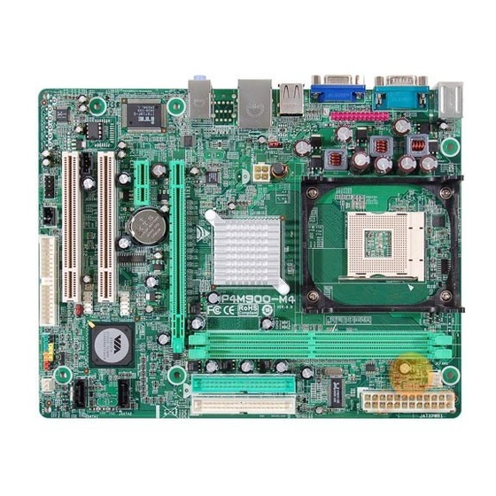
Page 7: Motherboard Layout
P4M900-M4 OTHERBOARD AYOUT JCFAN1 JKBMS1 Socket 478 CPU1 JATXPWR1 JUSB1 JUSBV1 JATXPWR2 JUSBLAN1 P4M900 JAUDIO1 (for Ver 5.x) JAUDIO2 (for Ver 6.x) PCI-EX16 BAT1 Super PCI-EX1_1 JSATA2 JUSB2 PCI1 VT8237A BIOS JUSB3 JSATA1 JCDIN1 PCI2 JUSBV2 JCMOS1 JAUDIOF1 JSFAN1 Codec... -
Page 8: Chapter 2: Hardware Installation
Motherboard Manual CHAPTER 2: HARDWARE INSTALLATION (CPU) NSTALLING ENTRAL ROCESSING Step 1: Pull the lever sideways away from the socket and then raise the lever up to a 90-degree angle. Step 2: Look for the white dot/cut edge. The white dot/cut edge should point wards the lever pivot. -
Page 9: Fan Headers
P4M900-M4 EADERS These fan headers support cooling-fans built in the computer. The fan cable and connector may be different according to the fan manufacturer. Connect the fan cable to the connector while matching the black wire to pin#1. JCFAN1: CPU Fan Header... -
Page 10: Installing System Memory
Motherboard Manual NSTALLING YSTEM EMORY A. Memory Modules Unlock a DIMM slot by pressing the retaining clips outward. Align a DIMM on the slot such that the notch on the DIMM matches the break on the Slot. Insert the DIMM vertically and firmly into the slot until the retaining chip snap back in place and the DIMM is properly seated. -
Page 11: Connectors And Slots
P4M900-M4 ONNECTORS AND LOTS FDD1: Floppy Disk Connector The motherboard provides a standard floppy disk connector that supports 360K, 720K, 1.2M, 1.44M and 2.88M floppy disk types. This connector supports the provided floppy drive ribbon cables. IDE1/IDE2: Hard Disk Connectors The motherboard has a 32-bit Enhanced PCI IDE Controller that provides PIO Mode 0~4, Bus Master, and Ultra DMA 33/66/100/133 functionality. - Page 12 Motherboard Manual PCI-EX16: PCI-Express x16 Slot PCI-Express 1.0a compliant. Maximum theoretical realized bandwidth of 4GB/s simultaneously per direction, for an aggregate of 8GB/s totally. PCI-EX1_1: PCI-Express x1 Slot PCI-Express 1.0a compliant. Data transfer bandwidth up to 250MB/s per direction; 500MB/s in total. PCI-Express supports a raw bit-rate of 2.5Gb/s on the data pins.
-
Page 13: Chapter 3: Headers & Jumpers Setup
P4M900-M4 CHAPTER 3: HEADERS & JUMPERS SETUP OW TO ETUP UMPERS The illustration shows how to set up jumpers. When the jumper cap is placed on pins, the jumper is “close”, if not, that means the jumper is “open”. Pin opened... - Page 14 Motherboard Manual ATX Power Source Connector: JATXPWR1 JATXPWR1 allows user to connect 24-pin power connector on the ATX power supply. Assignment Assignment +3.3V +3.3V -12V +3.3V Ground Ground PS_ON Ground Ground Ground Ground Ground PW_OK Standby Voltage+5V +12V +12V Ground +3.3V JATXPWR2: ATX Power Source Connector By connecting this connector, it will provide +12V to CPU power circuit.
- Page 15 P4M900-M4 JUSB2/JUSB3: Headers for USB 2.0 Ports at Front Panel This header allows user to connect additional USB cable on the PC front panel, and also can be connected with internal USB devices, like USB card reader. Assignment +5V (fused)
- Page 16 Motherboard Manual JAUDIOF1: Front Panel Audio Header This header allows user to connect the front audio output cable with the PC front panel. It will disable the output on back panel audio connectors. Assignment Mic Left in Ground Mic Right in GPIO Right line in Jack Sense...
-
Page 17: Clear Cmos Procedures
P4M900-M4 JCMOS1: Clear CMOS Header By placing the jumper on pin2-3, it allows user to restore the BIOS safe setting and the CMOS data, please carefully follow the procedures to avoid damaging the motherboard. Pin 1-2 Close: Normal Operation (default). - Page 18 Motherboard Manual JPRNT1: Printer Port Connector This header allows you to connector printer on the PC. Assignment Assignment -Strobe Ground -ALF Data 6 Data 0 Ground -Error Data 7 Data 1 Ground -Init -ACK Data 2 Ground -Scltin Busy Data 3 Ground Ground Data 4...
-
Page 19: Chapter 4: Useful Help
P4M900-M4 CHAPTER 4: USEFUL HELP RIVER NSTALLATION After you installed your operating system, please insert the Fully Setup Driver CD into your optical drive and install the driver for better system performance. You will see the following window after you insert the CD The setup guide will auto detect your motherboard and operating system. -
Page 20: Award Bios Beep Code
BIOS contents are corrupted. In this Case, please follow the procedure below to restore the BIOS: 1. Make a bootable floppy disk. 2. Download the Flash Utility “AWDFLASH.exe” from the Biostar website: www.biostar.com.tw 3. Confirm motherboard model and download the respectively BIOS from Biostar website. - Page 21 P4M900-M4 B. CPU Overheated If the system shutdown automatically after power on system for seconds, that means the CPU protection function has been activated. When the CPU is over heated, the motherboard will shutdown automatically to avoid a damage of the CPU, and the system may not power on again.
-
Page 22: Troubleshooting
Motherboard Manual ROUBLESHOOTING Probable Solution No power to the system at all Make sure power cable is Power light don’t illuminate, fan securely plugged in. inside power supply does not turn Replace cable. Contact technical support. Indicator light on keyboard does not turn on. -
Page 23: Chapter 5: Warpspeeder
P4M900-M4 WARPSPEEDER™ CHAPTER 5: NTRODUCTION [WarpSpeeder™], a new powerful control utility, features three user-friendly functions including Overclock Manager, Overvoltage Manager, and Hardware Monitor. With the Overclock Manager, users can easily adjust the frequency they prefer or they can get the best CPU performance with just one click. The Overvoltage Manager, on the other hand, helps to power up CPU core voltage and Memory voltage. -
Page 24: Installation
Motherboard Manual NSTALLATION 1. Execute the setup execution file, and then the following dialog will pop up. Please click “Next” button and follow the default procedure to install. 2. When you see the following dialog in setup procedure, it means setup is completed. -
Page 25: Warpspeeder
P4M900-M4 ™ PEEDER 1. Tray Icon Whenever the Tray Icon utility is launched, it will display a little tray icon on the right side of Windows Taskbar. This utility is responsible for conveniently invoking [WarpSpeeder™] Utility. You can use the mouse by clicking the left button in order to invoke [WarpSpeeder™] directly from the little tray icon or you can... - Page 26 Motherboard Manual 2. Main Panel If you click the tray icon, [WarpSpeeder™] utility will be invoked. Please refer to the following figure; the utility’s first window you will see is Main Panel. Main Panel contains features as follows: Display the CPU Speed, CPU external clock, Memory clock, AGP clock, and PCI clock information.
- Page 27 P4M900-M4 3. Voltage Panel Click the Voltage button in Main Panel, the button will be highlighted and the Voltage Panel will slide out to up as the following figure. In this panel, you can decide to increase CPU core voltage and Memory voltage or not.
- Page 28 Motherboard Manual 4. Overclock Panel Click the Overclock button in Main Panel, the button will be highlighted and the Overclock Panel will slide out to left as the following figure. Overclock Panel contains the these features: “–3MHz button”, “-1MHz button”, “+1MHz button”, and “+3MHz button”: provide user the ability to do real-time overclock adjustment.
- Page 29 P4M900-M4 “Auto-overclock button”: User can click this button and [WarpSpeeder™] will set the best and stable performance and frequency automatically. [WarpSpeeder™] utility will execute a series of testing until system fail. Then system will do fail-safe reboot by using Watchdog function. After reboot, the [WarpSpeeder™] utility will restore to the hardware default...
- Page 30 Motherboard Manual 6. About Panel Click the “about” button in Main Panel, the button will be highlighted and the About Panel will slide out to up as the following figure. In this panel, you can get model name and detail information in hints of all the chipset that are related to overclocking.
- Page 31 P4M900-M4 This page is intentionally left blank.
-
Page 32: Appendencies: Spec In Other Language
Motherboard Manual APPENDENCIES: SPEC IN OTHER LANGUAGE ERMAN Ver 5.x Ver 6.x Sockel 478 Sockel 478 Intel Pentium 4 / Celeron D Prozessoren Intel Pentium 4 / Celeron D Prozessoren mit bis zu 3,4 GHz (Unterstützt keine mit bis zu 3,4 GHz (Unterstützt keine Willamette CPUs) Willamette CPUs) Unterstützt Hyper-Threading Technology... - Page 33 190 mm (B) X 244 mm (L) ße. Windows 2K / XP / VISTA Windows 2K / XP / VISTA Biostar behält sich das Recht vor, ohne Biostar behält sich das Recht vor, ohne OS-Unterst Ankündigung die Unterstützung für ein Ankündigung die Unterstützung für ein...
-
Page 34: French
Motherboard Manual RENCH Ver 5.x Ver 6.x Socket 478 Socket 478 Processeurs Intel Pentium 4 / Celeron D Processeurs Intel Pentium 4 / Celeron D jusqu'à 3,4 GHz (pas de prise en charge des jusqu'à 3,4 GHz (pas de prise en charge des UC Willamette) UC Willamette) Prend en charge les technologies... - Page 35 Windows 2K / XP / VISTA Windows 2K / XP / VISTA Support Biostar se réserve le droit d'ajouter ou de Biostar se réserve le droit d'ajouter ou de supprimer le support de SE avec ou sans supprimer le support de SE avec ou sans préavis.
-
Page 36: Italian
Motherboard Manual TALIAN Ver 5.x Ver 6.x Socket 478 Socket 478 Processore Intel Pentium 4 / Celeron D fino Processore Intel Pentium 4 / Celeron D fino a 3.4 GHz (Non supporta CPU Willamette) a 3.4 GHz (Non supporta CPU Willamette) Supporto di Hyper-Threading Supporto di Hyper-Threading *It is recommended to use processors with... - Page 37 Windows 2K / XP / VISTA Windows 2K / XP / VISTA Sistemi Biostar si riserva il diritto di aggiungere o Biostar si riserva il diritto di aggiungere o operativi rimuovere il supporto di qualsiasi sistema rimuovere il supporto di qualsiasi sistema supportati operativo senza preavviso.
-
Page 38: Spanish
Motherboard Manual PANISH Ver 5.x Ver 6.x Conector 478 Conector 478 Procesador Intel Pentium 4 / Celeron D Procesador Intel Pentium 4 / Celeron D hasta 3,4 GHz (no soporta CPU Willamette) hasta 3,4 GHz (no soporta CPU Willamette) Admite Hyper-Threading Admite Hyper-Threading *It is recommended to use processors with *It is recommended to use processors with... - Page 39 Windows 2K / XP / VISTA Windows 2K / XP / VISTA Soporte de Biostar se reserva el derecho de añadir o Biostar se reserva el derecho de añadir o sistema retirar el soporte de cualquier SO con o sin...
-
Page 40: Portuguese
Motherboard Manual ORTUGUESE Ver 5.x Ver 6.x Socket 478 Socket 478 Processador Intel Pentium 4 / Celeron D até Processador Intel Pentium 4 / Celeron D até 3,4 GHz (não suporta a CPU Willamette) 3,4 GHz (não suporta a CPU Willamette) Suporta as tecnologias Hyper-Threading Suporta as tecnologias Hyper-Threading *It is recommended to use processors with... - Page 41 Sistemas Windows 2K / XP / VISTA Windows 2K / XP / VISTA operativos A Biostar reserva-se o direito de adicionar A Biostar reserva-se o direito de adicionar suportado ou remover suporte para qualquer sistema ou remover suporte para qualquer sistema operativo com ou sem aviso prévio.
-
Page 42: Polish
Motherboard Manual OLISH Ver 5.x Ver 6.x Socket 478 Socket 478 Procesor Intel Pentium 4 / Celeron D do 3,4 Procesor Intel Pentium 4 / Celeron D do 3,4 GHz (brak obsługi procesorów Willamette) GHz (brak obsługi procesorów Willamette) Procesor Obsługa Hyper-Threading Technology Obsługa Hyper-Threading Technology *It is recommended to use processors with... - Page 43 190 mm (S) X 244 mm (W) płyty Obsluga Windows 2K / XP / VISTA Windows 2K / XP / VISTA systemu Biostar zastrzega sobie prawo dodawania Biostar zastrzega sobie prawo dodawania operacyjn lub odwoływania obsługi dowolnego lub odwoływania obsługi dowolnego systemu operacyjnego bez powiadomienia.
-
Page 44: Russian
Motherboard Manual USSIAN Ver 5.x Ver 6.x Гнездо 478 Гнездо 478 Процессор Intel Pentium 4 / Celeron D до Процессор Intel Pentium 4 / Celeron D до 3.4 ГГц ( не поддерживает центральные 3.4 ГГц ( не поддерживает центральные (централь процессоры... - Page 45 190 мм (Ш) X 244 мм (В) 190 мм (Ш) X 244 мм (В) панели Windows 2K / XP / VISTA Windows 2K / XP / VISTA Biostar сохраняет за собой право Biostar сохраняет за собой право Поддержк добавлять или удалять средства добавлять или удалять средства...
-
Page 46: Arabic
Motherboard Manual RABIC Ver 6.x Ver 5.x 874ﻡﻘﺒﺲ 874ﻡﻘﺒﺲ ﻡﻌﺎﻟﺠﺎتIntel Pentium 4 / Celeron D ﻡﻌﺎﻟﺠﺎتIntel Pentium 4 / Celeron D ﺼﻞ ﻳ ﺘﺮدد ﺏ ﺼﻞ ﻳ ﺘﺮدد ﺏ ﺝﻴﺠﺎ هﺮﺕﺰ إﻟﻰ ﺝﻴﺠﺎ هﺮﺕﺰ إﻟﻰ اﻟﻤﻌﺎﻟﺠﺔ وﺣﺪة ﻻ ﺕﺪﻋﻢ وﺣﺪة اﻟﻤﻌﺎﻟﺠﺔ اﻟﻤﺮآﺰﻳﺔWillamette ﻻ... -
Page 47: Pci Express
P4M900-M4 Ver 6.x Ver 5.x Realtek RTL 8201CL PHY Realtek RTL 8201CL PHY ﺙﺎﻥﻴﺔ ﻡﻴﺠﺎ ﺏﺎﻳﺖ ﺕﻔﺎوض ﺕﻠﻘﺎﺋﻲ ﺙﺎﻥﻴﺔ ﻡﻴﺠﺎ ﺏﺎﻳﺖ ﺕﻔﺎوض ﺕﻠﻘﺎﺋﻲ داﺥﻠﻴﺔ ﺵﺒﻜﺔ اﻟﻨﺼﻔﻲ إﻡﻜﺎﻥﻴﺔ اﻟﻨﻘﻞ اﻟﻤﺰدوج اﻟﻜﺎﻡﻞ اﻟﻨﺼﻔﻲ إﻡﻜﺎﻥﻴﺔ اﻟﻨﻘﻞ اﻟﻤﺰدوج اﻟﻜﺎﻡﻞ VT1708B / ALC662 / ALC861VD ALC883 ﺕﺪﻋﻢ... -
Page 48: Japanese
Motherboard Manual APANESE Ver 5.x Ver 6.x Socket 478 Socket 478 Intel Pent ium 4 / Celeron D processor up to Intel Pent ium 4 / Celeron D processor up to 3.4 GHz (Willamette CPUはサポートしませ 3.4 GHz (Willamette CPUはサポートしませ ん) ん) Hyper-Threading Technology をサポートしま... - Page 49 P4M900-M4 Ver 5.x Ver 6.x Realtek RTL 8201CL PHY Realtek RTL 8201CL PHY LAN PHY 10 / 100 Mb/秒のオートネゴシエーション 10 / 100 Mb/秒のオートネゴシエーション 半/全二重機能 半/全二重機能 ALC883 VT1708B / ALC662 / ALC861VD サウンド ハイデフィニションオーディオのサポート ハイデフィニションオーディオのサポート Codec 7.1 チャンネルオーディオアウト 5.1 チャンネルオーディオアウト PCIスロット...
Need help?
Do you have a question about the P4M900-M4 and is the answer not in the manual?
Questions and answers