Table of Contents
Advertisement
P4M80-M4
FCC Information and Copyright
This equipment has been tested and found to comply with the limits of a Class
B digital device, pursuant to Part 15 of the FCC Rules. These limits are designed
to provide reasonable protection against harmful interference in a residential
installation. This equipment generates, uses and can radiate radio frequency
energy and, if not installed and used in accordance with the instructions, may
cause harmful interference to radio communications. There is no guarantee
that interference will not occur in a particular installation.
The vendor makes no representations or warranties with respect to the
contents here and specially disclaims any implied warranties of merchantability
or fitness for any purpose. Further the vendor reserves the right to revise this
publication and to make changes to the contents here without obligation to
notify any party beforehand.
Duplication of this publication, in part or in whole, is not allowed without first
obtaining the vendor's approval in writing.
The content of this user's manual is subject to be changed without notice and
we will not be responsible for any mistakes found in this user's manual. All the
brand and product names are trademarks of their respective companies.
i
Advertisement
Table of Contents

Related Manuals for Biostar P4M80-M4


Summary of Contents for Biostar P4M80-M4
- Page 1 P4M80-M4 FCC Information and Copyright This equipment has been tested and found to comply with the limits of a Class B digital device, pursuant to Part 15 of the FCC Rules. These limits are designed to provide reasonable protection against harmful interference in a residential installation.
-
Page 2: Table Of Contents
Table of Contents Chapter 1: Introduction ... 1 Motherboard Features ... 1 Package Checklist ... 4 Layout and Components ... 5 Chapter 2: Hardware Installation ... 6 Installing Central Processing Unit (CPU) ... 6 FAN Headers ... 7 Installing System Memory ... 8 Connectors and Slots ... -
Page 3: Chapter 1: Introduction
Controller integrated in SB VT8237R. Supports RAID 0 and RAID 1 functions. Supports 2 Serial ATA (SATA) devices. Compliant with SATA Version 1.0 specification. Data transfer rate up to 150 MB/s. P4M80-M4 EATURES DDR Module 128MB/256MB/512MB/1GB *1 128MB/256MB/512MB/1GB *1 Total Memory Size Max is 2GB. - Page 4 P4M80-M4 Super I/O Chip: ITE IT8705AF. Provides the most commonly used legacy Super I/O functionality. Environment Control initiatives: H/W Monitor Fan Speed Controller ITE's "Smart Guardian" function On Board IDE Two on-board connectors support 4 devices. Supports PIO Mode 0~4.
- Page 5 P4M80-M4 Internal On-board I/O Connectors and Headers 1 front panel header supports front panel facilities. 1 CD-in connector supports 1 CD-ROM audio-in device. 1 front audio header supports front panel audio-out function. 1 SPDIF-out connector supports digital audio-out function. 1 chassis open header supports PC case-opened warning function.
-
Page 6: Bios & Software
HDD Cable X 1 User’s Manual X 1 Fully Setup Driver CD X 1 USB 2.0 Cable X1 (optional) Serial ATA Cable X 2 (optional) SPDIF out Cable X 1 (optional) Rear I/O Panel for ATX Case X 1 P4M80-M4... -
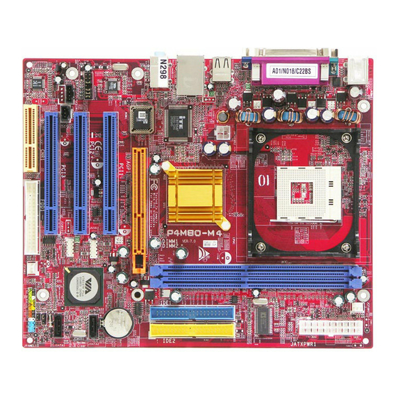
Page 7: Layout And Components
JATXPWR2 JUSB1 JUSBLAN1 Super JAUDIO BIOS PCI1 PCI2 JAUDIO1 JCDIN1 JSPDIFO1 JAUX1 (optional) PCI3 Codec CNR1 Note: ■ represents the 1 P4M80-M4 JCFAN1 Socket 478 CPU1 P4M800 AGP1 JUSB3 VT8237R JUSB4 FDD1 JSFAN1 pin. BAT1 JSATA2 JSATA1 JCMOS1 JCI1 JPANEL1... -
Page 8: Chapter 2: Hardware Installation
Step 3: Hold the CPU down firmly, and then close the lever to complete the installation. Step 4: Put the CPU Fan on the CPU and buckle it. Connect the CPU FAN power cable to the JCFAN1. This completes the installation. P4M80-M4 (CPU) ROCESSING... -
Page 9: Fan Headers
The JCFAN1 and JSFAN1 support 3-pin head connector. When connecting with wires onto connectors, please note that the red wire is the positive and should be connected to pin#2, and the black wire is Ground and should be connected to GND. P4M80-M4 JCFAN1 JSFAN1... -
Page 10: Installing System Memory
DIMM on the slot such that the notch on the DIMM matches the break on the Slot. Insert the DIMM vertically and firmly into the slot until the retaining chip snap back in place and the DIMM is properly seated. P4M80-M4 EMORY... -
Page 11: Connectors And Slots
This connector supports the provided floppy drive ribbon cables. IDE1/IDE2: Hard Disk Connectors The motherboard has a 32-bit Enhanced PCI IDE Controller that provides PIO Mode 0~4, Bus Master, and Ultra DMA 33/66/100/133 functionality. It has two HDD connectors IDE1 (primary) and IDE2 (secondary). - Page 12 P4M80-M4 PCI1~PCI3: Peripheral Component Interconnect Slots This motherboard is equipped with 3 standard PCI slots. PCI stands for Peripheral Component Interconnect, and it is a bus standard for expansion cards. This PCI slot is designated as 32 bits. AGP1: Accelerated Graphics Port Slot Your monitor will attach directly to that video card.
- Page 13 P4M80-M4 CNR1: Communication Network Riser Slot The CNR specification is an open Industry Standard Architecture, and it defines a hardware scalable riser card interface, which supports modem only.
-
Page 14: Chapter 3: Headers & Jumpers Setup
“close”, if not, that means the jumper is “open”. Pin opened ETAIL ETTINGS JATXPWR1: ATX Power Connector This connector allows user to connect 20-pin power connector on the ATX power supply. P4M80-M4 Pin closed Pin1-2 closed Assignment +3.3V +3.3V Ground Ground... - Page 15 P4M80-M4 JATXPWR2: ATX Power Connector By connecting this connector, it will provide +12V to CPU power circuit. JAUDIO1: Front Panel Audio Header This header allows user to connect the front audio output cable with the PC front panel. It will disable the output on back panel audio connectors.
-
Page 16: Digital Audio-Out Connector
P4M80-M4 JSPDIFO1: Digital Audio-out Connector This connector allows user to connect the PCI bracket SPDIF output header. JPANEL1: Front Panel Header This 24-pin connector includes Power-on, Reset, HDD LED, Power LED, Sleep button, speaker and IrDA Connection. It allows user to connect the PC case’s front panel switch functions. -
Page 17: Clear Cmos Header
P4M80-M4 JUSB3/JUSB4: Front USB Headers This motherboard provides 2 USB 2.0 headers, which allows user to connect additional USB cable on the PC front panel, and also can be connected with internal USB devices, like USB card reader. JCMOS1: Clear CMOS Header... - Page 18 P4M80-M4 JSATA1/JSATA2: Serial ATA Connectors The motherboard has a PCI to SATA Controller with 2 channels SATA interface, it satisfies the SATA 1.0 spec and with transfer rate of 1.5Gb/s. JCDIN1: CD-ROM Audio-in Connector This connector allows user to connect the audio source from the variety devices, like CD-ROM, DVD-ROM, PCI sound card, PCI TV turner card etc..
- Page 19 P4M80-M4 JCI1: Chassis Open Header This connector allows system to monitor PC case open status. If the signal has been triggered, it will record to the CMOS and show the message on next boot-up. Assignment Case open signal Ground...
-
Page 20: Chapter 4: Useful Help
BIOS contents are corrupted. In this Case, please follow the procedure below to restore the BIOS: Make a bootable floppy disk. Download the Flash Utility “AWDFLASH.exe” from the Biostar website: www.biostar.com.tw Confirm motherboard model and download the respectively BIOS from Biostar website. -
Page 21: Cpu Overheated
If the system shutdown automatically after power on system for seconds, that means the CPU protection function has been activated. When the CPU is over heated, the motherboard will shutdown automatically to avoid a damage of the CPU, and the system may not power on again. -
Page 22: Troubleshooting
Screen message says “Invalid Configuration” or “CMOS Failure.” Cannot boot system after installing second hard drive. P4M80-M4 Solution Make sure power cable is securely plugged in. Replace cable. Contact technical support. -
Page 23: Chapter 5: Warpspeeder
YSTEM EQUIREMENT OS Support: Windows 98 SE, Windows Me, Windows 2000, Windows XP DirectX: DirectX 8.1 or above. (The Windows XP operating system includes DirectX 8.1. If you use Windows XP, you do not need to install DirectX 8.1.) P4M80-M4... -
Page 24: Installation
Tray Icon utility and [WarpSpeeder™] utility will be automatically and immediately launched after you click “Finish” button. Usage: The following figures are just only for reference, the screen printed in this user manual will change according to your motherboard on hand. P4M80-M4... -
Page 25: Warpspeeder™] Includes 1 Tray Icon And 5 Panels
P4M80-M4 ™] PEEDER INCLUDES TRAY ICON AND PANELS 1. Tray Icon: Whenever the Tray Icon utility is launched, it will display a little tray icon on the right side of Windows Taskbar. This utility is responsible for conveniently invoking [WarpSpeeder™] Utility. -
Page 26: Main Panel
P4M80-M4 2. Main Panel If you click the tray icon, [WarpSpeeder™] utility will be invoked. Please refer to the following figure; the utility’s first window you will see is Main Panel. Main Panel contains features as follows: a. Display the CPU Speed, CPU external clock, Memory clock, AGP clock, and PCI clock information. - Page 27 P4M80-M4 3. Voltage Panel Click the Voltage button in Main Panel, the button will be highlighted and the Voltage Panel will slide out to up as the following figure. In this panel, you can decide to increase CPU core voltage and Memory voltage or not.
- Page 28 P4M80-M4 4. Overclock Panel Click the Overclock button in Main Panel, the button will be highlighted and the Overclock Panel will slide out to left as the following figure. Overclock Panel contains the these features: a. “–3MHz button”, “-1MHz button”, “+1MHz button”, and “+3MHz button”: provide user the ability to do real-time overclock adjustment.
- Page 29 P4M80-M4 “Auto-overclock button”: User can click this button and [WarpSpeeder™] will set the best and stable performance and frequency automatically. [WarpSpeeder™] utility will execute a series of testing until system fail. Then system will do fail-safe reboot by using Watchdog function. After reboot, the [WarpSpeeder™] utility will restore to the hardware default...
-
Page 30: About Panel
P4M80-M4 6. About Panel Click the “about” button in Main Panel, the button will be highlighted and the About Panel will slide out to up as the following figure. In this panel, you can get model name and detail information in hints of all the chipset that are related to overclocking. - Page 31 P4M80-M4 Note: Because the overclock, overvoltage, and hardware monitor features are controlled by several separate chipset, [WarpSpeeder™] divide these features to separate panels. If one chipset is not on board, the correlative button in Main panel will be disabled, but will not interfere other panels’...
Need help?
Do you have a question about the P4M80-M4 and is the answer not in the manual?
Questions and answers