Table of Contents
Advertisement
P4M900 Micro 775 Setup Manual
FCC Information and Copyright
This equipment has been tes ted and found to comply with the limits of a Class
B digital devic e, purs uant to Part 15 of the FCC Rules . T hese limits are designed
to provide reasonable protec tion against harmful interference in a residential
installation. T his equipment generates , uses and can radiate radio frequency
energy and, if not ins talled and used in accordance with the instructions , may
cause harmful interference to radio communications . There is no guarantee
that interference will not occur in a particular ins tallation.
The vendor makes no representations or warranties with respec t to the
contents here and s pecially disclaims any implied warranties of merchantability
or fitness for any purpose. Further the vendor reserves the right to revise this
publication and to make c hanges to the c ontents here without obligation to
notify any party beforehand.
D uplication of this publication, in part or in whole, is not allowed without first
obtaining the vendor's approval in writing.
The content of this user's manual is subject to be c hanged without notice and
we will not be res ponsible for any mis takes found in this user's manual. All the
brand and produc t names are trademarks of their respec tive companies .
Advertisement
Chapters
Table of Contents

Related Manuals for Biostar P4M900 Micro 775


Summary of Contents for Biostar P4M900 Micro 775
- Page 1 P4M900 Micro 775 Setup Manual FCC Information and Copyright This equipment has been tes ted and found to comply with the limits of a Class B digital devic e, purs uant to Part 15 of the FCC Rules . T hese limits are designed to provide reasonable protec tion against harmful interference in a residential installation.
-
Page 2: Table Of Contents
Table of Contents Chapter 1: INTRODUCTION........3 Before You Start..............3 Package Checklist..............3 Motherboard FeaturesS............4 Rear Panel Connectors (for Ver 5.x)........6 Rear Panel Connectors (for Ver 6.x )........6 Motherboard Layout (for Ver 5.x ).......... 7 Motherboard Layout (for Ver 6.x ).......... 8 Chapter 2: Hardware Installation...... -
Page 3: Chapter 1: Introduction
P4M900 Micro 775 CHAPTER 1: INTRODUCTION EFORE T ART Thank you for choosing our product. Be fore you start installing the mothe rboard, please make sure you follow the instructions be low: Prepare a dry and stable work ing environment with sufficie nt lighting. -
Page 4: Motherboard Featuress
Motherboard Manual OT HERBOARD EAT URES Ver 5.x Ver 6.x LGA 775 LGA 775 Intel Core2Duo/ Pe ntium 4 / Pentium D / Intel Core2Duo/ Pe ntium 4 / Pentium D / Celeron D pr ocessor up to 3.8 GHz Celeron D pr ocessor up to 3.8 GHz Supports Hyper Thre ading/ Ex ecute Disable Supports Hyper Thre ading/ Ex ecute Disable... - Page 5 190 mm (W) x 244 mm (L) Windows 2000 / XP / VISTA Windows 2000 / XP / VISTA Biostar Reserves the right to add or remo ve Biostar Reserves the right to add or remove Support support for any OS with or witho ut notice.
-
Page 6: Rear Panel Connectors (For Ver 5.X)
Motherboard Manual ANEL ONNECT ORS PS/2 Printer Port AU DIO JAC K Mou se PS/2 USBX2 USBX2 COM1 Ke yboard Center Li ne In Rear Li ne Out Side Mic In ANEL ONNECT ORS PS/2 Printer Port Li ne In/ Mouse Surround Line Out... -
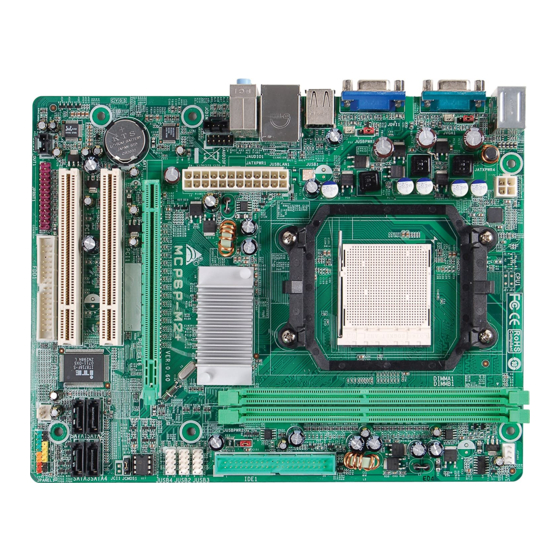
Page 7: Motherboard Layout (For Ver 5.X )
P4M900 Micro 775 OT HERBOARD AYOUT JCFAN1 J KBMS 1 LGA775 CPU1 JATXPWR1 JUSB2 JUSBV1 JATXPWR2 P4M900 JRJ45USB1 J AUDIO1 PCI-EX16 BAT1 Super PCI-EX1_1 JSATA2 JUSB2 PCI1 VT8237A BIOS JCDIN1 JSATA1 JUSB3 PCI2 JUSBV2 JCMOS1 JSPDIF_OUT1 JAUDIO2 Codec FDD1 JSFAN1... -
Page 8: Motherboard Layout (For Ver 6.X )
Motherboard Manual OT HERBOARD AYOUT JCFAN1 J KBMS 1 LGA775 CPU1 JATXPW R1 JUSB2 JUSBV1 JATXPWR2 P4M900 JRJ45USB1 JA UDIO1 PCI-EX16 BAT1 Super PCI-EX1_1 JSATA2 JUSB2 PCI1 VT8237A BIOS JCDIN1 JSATA1 JUSB3 PCI2 JUSBV2 JCMOS1 JSPDIF_OUT1 JAUDIO2 Codec FDD1 JSFAN1 JPANEL1 Not e: represe nts the 1... -
Page 9: Chapter 2: Hardware Installation
P4M900 Micro 775 CHAPTER 2: HARDWARE INSTALLATION (CPU) NST ALLING ENT RAL ROCESSING Special Notice: Remove Pin Cap before installation, and make good preservation for future use. When the CPU is removed, cover the Pin Cap on the empty socket to ensure pin legs won’t be damaged. - Page 10 Motherboard Manual Look for the triangular cut edge on socket, and the golden dot on Step 2: CPU should point forwards this triangular cut edge. The CPU will fit only in the correct orientation. Step 2-1: Step 2-2: Hold the CPU down firmly, and then lower the lever to locked Step 3: position to complete the installation.
-
Page 11: Fan Headers
P4M900 Micro 775 EADERS These fan headers support cooling-fans built in the computer. The fan cable and connector may be different according to the fan manufacturer. Connect the fan cable to the connector while matching the black wire to pin#1. -
Page 12: Installing System Memory
Motherboard Manual NST ALLING YST EM EMORY A. Memory Modules Unlock a DIMM slot by pressing the retaining clips outward. Align a DIMM on the slot such that the notch on the DIMM matches the break on the Slot. Insert the DIMM vertically and firmly into the slot until the retaining chip snap back in place and the DIMM is properly seated. -
Page 13: Connectors And Slots
P4M900 Micro 775 ONNECT ORS AND LOT S FDD1: Floppy Disk Conne ctor The motherboard prov ides a standard floppy disk connector that supports 360K, 720K, 1.2M, 1.44M and 2.88M floppy disk ty pes. This connector supports the prov ided f loppy drive ribbon cables. - Page 14 Motherboard Manual PCI-EX16: PCI-Express x16 Slot PCI-Express 1.0a compliant. Maximum theoretical realized bandwidth of 4GB/s simultaneously per direction, f or an aggregate of 8GB/s totally. PCI-EX1_1: PCI-Express x1 slots PCI-Express 1.0a compliant. Data transf er bandwidth up to 250MB/s per direction; 500MB/s in total. PCI-Express supports a raw bit-rate of 2.5Gb/s on the data pins.
-
Page 15: Chapter 3: Headers & Jumpers Setup
P4M900 Micro 775 CHAPTER 3: HEADERS & JUMPERS SETUP OW T O ET UP UMPERS The illustration shows how to set up jumpers. When the jumper cap is placed on pins, the jumper is “close”, if not, that means the jumper is “open”. - Page 16 Motherboard Manual ATX Power Source Conne ctor: JATXPWR1 JATXPWR1 allows user to connect 24-pin power connector on the ATX power supply. Assignment Assignment +3.3V +3.3V -12V +3.3V Ground Ground PS_ON Ground Ground Ground Ground Ground PW_OK Standby Voltage+5V +12V +12V Ground +3.3V JATXPWR2: ATX Powe r Source Conne ctor...
- Page 17 P4M900 Micro 775 JUSB2/JUSB3: Heade rs for USB 2.0 Ports at Front Panel This header allows user to connect additional USB cable on the PC f ront panel, and also can be connected with internal USB devices, like USB card reader.
-
Page 18: Cd-Rom Audio-In Connector
Motherboard Manual JAUDIO 2: Front Panel Audio Heade r This header allows user to connect the front audio output cable with the PC f ront panel. It will disable the output on back panel audio connectors. Assignment Mic Left in Ground Mic Right in GPIO... - Page 19 P4M900 Micro 775 JCMO S1: Cle ar CMOS Heade r By placing the jumper on pin2-3, it allows user to restore the BIOS saf e setting and the CMOS data, please carefully f ollow the procedures to avoid damaging the motherboard.
- Page 20 Motherboard Manual JSPDIF_O UT1: Digital Audio-out Conne ctor This connector allows user to connect the PCI bracket SPDIF output header. Assignment SPDIF_OUT Ground...
-
Page 21: Chapter 4: Useful Help
P4M900 Micro 775 CHAPTER 4: USEFUL HELP RIVER NST ALLAT ION OT E After you installed your operating system, please insert the Fully Setup Driver CD into your optical drive and install the driver for better system performance. You will see the following window after you insert the CD The setup guide will auto detect your motherboard and operating system. -
Page 22: Award Bios Beep Code
BIOS contents are corrupted. In this Case, please follow the procedure below to restore the BIOS: 1. Make a bootable floppy disk. 2. Download the Flash Utility “AWDFLASH.exe” from the Biostar website: www.biostar.com.tw 3. Confirm motherboard model and download the respectively BIOS from Biostar website. - Page 23 P4M900 Micro 775 B. CPU Overheated If the system shutdown automatically after power on system for seconds, that means the CPU protection function has been activated. When the CPU is over heated, the motherboard will shutdown automatically to avoid a damage of the CPU, and the system may not power on again.
-
Page 24: Troubleshooting
Motherboard Manual 4.4 T ROUBLESHOOT ING Probable Solution No power to the system at all Make sure power cable is Power light don’t illuminate, f an securely plugged in. inside power supply does not turn Replace cable. Contact technical support. Indicator light on key board does not turn on. -
Page 25: Chapter 5: Warpspeeder
P4M900 Micro 775 WARPSPEEDER™ CHAPTER 5: NT RODUCT ION [WarpSpeeder™], a new powerful control utility, features three user-friendly functions including Overclock Manager, Overvoltage Manager, and Hardware Monitor. With the Overclock Manager, users can easily adjust the frequency they prefer or they can get the best CPU performance with just one click. The Overvoltage Manager, on the other hand, helps to power up CPU core voltage and Memory voltage. -
Page 26: Installation
Motherboard Manual NST ALLAT ION 1. Execute the setup execution file, and then the following dialog will pop up. Please click “Next” button and follow the default procedure to install. 2. When you see the following dialog in setup procedure, it means setup is completed. -
Page 27: Warpspeeder
P4M900 Micro 775 ™ PEEDER 1. Tray Icon: Whenever the Tray Icon utility is launched, it will display a little tray icon on the right side of Windows Taskbar. This utility is responsible for conveniently invoking [WarpSpeeder™] Utility. Y ou can use the mouse by clicking the left button in order to invoke [WarpSpeeder™] directly from the little tray icon or you can... - Page 28 Motherboard Manual 2. Main Panel If you click the tray icon, [WarpSpeeder™] utility will be invoked. Please refer to the following figure; the utility’s first window you will see is Main Panel. Main Panel contains fe ature s as follows: a.
- Page 29 P4M900 Micro 775 3. Voltage Panel Click the Voltage button in Main Panel, the button will be highlighted and the Voltage Panel will slide out to up as the following figure. In this panel, you can decide to increase CPU core voltage and Memory voltage or not.
- Page 30 Motherboard Manual 4. Overclock Panel Click the Overclock button in Main Panel, the button will be highlighted and the Overclock Panel will slide out to left as the following figure. O ve rclock Panel contains the these features: a. “–3MHz button”, “-1MHz button”, “+1MHz button”, and “+3MHz button”: provide user the ability to do real-time overclock adjustment.
- Page 31 P4M900 Micro 775 “Auto-overclock button”: User can click this button and [WarpSpeeder™] will set the best and stable performance and frequency automatically. [W arpSpeeder™] utility will execute a series of testing until system fail. Then system will do fail-safe reboot by using Watchdog function. After reboot, the [WarpSpeeder™] utility will restore to the hardware default...
- Page 32 Motherboard Manual 6. About Panel Click the “about” button in Main Panel, the button will be highlighted and the About Panel will slide out to up as the following figure. In this panel, you can get model name and detail information in hints of all the chipset that are related to overclocking.
- Page 33 P4M900 Micro 775 This page is intentionally left blank...
-
Page 34: Appendencies: Spec In Other Language
Motherboard Manual APPENDENCIES: SPEC IN OTHER LANGUAGE ERMAN Ver 5.x Ver 6.x LGA 775 LGA 775 Intel Core2Duo/ Pe ntium 4 / Pentium D / Intel Core2Duo/ Pe ntium 4 / Pentium D / Celeron D Pr ozessoren mit bis zu 3,8 GHz Celeron D Pr ozessoren mit bis zu 3,8 GHz Unterstützt Hyper-Thre ading / Execute Unterstützt Hyper-Thre ading / Execute... - Page 35 190 mm (B) X 244 mm (L) ße. Windows 2K / XP / VISTA Windows 2K / XP / VISTA Biostar behält sich das Recht v or, ohne Biostar behält sich das Recht v or, ohne OS-Unterst Ankündigung die Unterstützung für ei n Ankündigung die Unterstützung für ei n...
-
Page 36: France
Motherboard Manual RANCE Ver 5.x Ver 6.x LGA 775 LGA 775 Processeurs Intel Core 2Duo/ P entium 4 / Processeurs Intel Core 2Duo/ P entium 4 / Pentium D / Celeron D jusqu'à 3,8 GHz Pentium D / Celeron D jusqu'à 3,8 GHz Prend en charge les technologies Prend en charge les technologies Hyper -Thre ading / d'ex écution de bit de... - Page 37 Windows 2K / XP / VISTA Windows 2K / XP / VISTA Support Biostar se réserve le droit d'ajo uter o u de Biostar se réserve le droit d'ajo uter o u de supprimer le support de SE avec o u sa ns supprimer le support de SE avec o u sa ns préavis.
-
Page 38: Italian
Motherboard Manual T ALIAN Ver 5.x Ver 6.x LGA 775 LGA 775 Processore Intel Core 2Duo/ Pentium 4 / Processore Intel Core 2Duo/ Pentium 4 / Pentium D / Celeron D fino a 3.8 GHz Pentium D / Celeron D fino a 3.8 GHz Supporto di Hyper -Threadi ng / Execute Supporto di Hyper -Threadi ng / Execute Disable Bit / Enha nced I ntel Spee dStep®... - Page 39 Windows 2K / XP / VISTA Windows 2K / XP / VISTA Sistemi Biostar si riserva il diritto di aggiungere o Biostar si riserva il diritto di aggiungere o operativi rimuovere il supporto di qualsiasi sistema rimuovere il supporto di qualsiasi sistema supportati operativo se nza pre avviso.
-
Page 40: Spanish
Motherboard Manual PANISH Ver 5.x Ver 6.x LGA 775 LGA 775 Procesador I ntel Core 2Duo/ P entium 4 / Procesador I ntel Core 2Duo/ P entium 4 / Pentium D / Celeron D hasta 3,8 GHz Pentium D / Celeron D hasta 3,8 GHz Admite Hyper -Threadi ng / Bit de Admite Hyper -Threadi ng / Bit de deshabilitación de ejecució... - Page 41 Windows 2K / XP / VISTA Windows 2K / XP / VISTA Soporte de Biostar se reserva el derecho de a ñadir o Biostar se reserva el derecho de a ñadir o sistema retirar el soporte de cualquier SO con o sin...
-
Page 42: Portuguese
Motherboard Manual ORT UGUESE Ver 5.x Ver 6.x LGA 775 LGA 775 Processador Intel Core2Duo / Pe ntium 4 / Processador Intel Core2Duo / Pe ntium 4 / Pentium D / Celeron D até 3,8 GHz Pentium D / Celeron D até 3,8 GHz Suporta as tecnologias Hyper -Threa ding / Suporta as tecnologias Hyper -Threa ding / Execute Disable Bit / Enha nced I ntel... - Page 43 Sistemas Windows 2K / XP / VISTA Windows 2K / XP / VISTA operativos A Biostar reserva-se o direito de adicionar A Biostar reserva-se o direito de adicionar suportado ou remov er suporte para qualquer sistema ou remov er suporte para qualquer sistema operativo com ou sem aviso prévio.
-
Page 44: Polish
Motherboard Manual OLISH Ver 5.x Ver 6.x LGA 775 LGA 775 Procesor Intel Cor e2Duo/ Penti um 4 / Procesor Intel Cor e2Duo/ Penti um 4 / Pentium D / Celeron D do 3,8 GHz Pentium D / Celeron D do 3,8 GHz Obsługa Hyper-Threa ding / Exec ute Disable Obsługa Hyper-Threa ding / Exec ute Disable Procesor... - Page 45 Obsluga Windows 2K / XP / VISTA Windows 2K / XP / VISTA systemu Biostar zastrzega sobie prawo do dawania Biostar zastrzega sobie prawo do dawania operacyjn lub o dwoływania obsługi dowolne go lub o dwoływania obsługi dowolne go systemu operacyjnego bez powiadomienia.
-
Page 46: Russian
Motherboard Manual USSIAN Ver 5.x Ver 6.x LGA 775 LGA 775 Процессор Intel Core 2Duo/ Pe ntium 4 / Процессор Intel Core 2Duo/ Pe ntium 4 / Pentium D / Celeron D до 3.8 ГГц Pentium D / Celeron D до 3.8 ГГц (центра... - Page 47 190 мм (Ш) X 244 мм (В) пане ли Windows 2K / XP / VISTA Windows 2K / XP / VISTA Biostar сохраня ет за собо й прав о Biostar сохраня ет за собо й прав о Подде ржк добав лять или уда лять средс тва...
-
Page 48: Arabic
Motherboard Manual RABIC Ver 6.x Ver 5.x LGA 775 LGA 775 ﻡﻌﺎﻟﺠﺎتIntel Core2Duo/ Pe ntium 4 / Pentium ﻡﻌﺎﻟﺠﺎتIntel Core2Duo/ Pe ntium 4 / Pentium D / C eleron D D / C eleron D ﺝﻴﺠﺎ هﺮﺕﺰ ﺼﻞ إﻟﻰ ﻳ ﺘﺮدد... -
Page 49: Pci Express X16
P4M900 Micro 775 Ver 6.x Ver 5.x Realtek RTL 8201CL Realtek RTL 8201CL ﺙﺎﻥﻴﺔ ﻡﻴﺠﺎ ﺑﺎﻳﺖ ﺕﻔﺎوض ﺕﻠﻘﺎﺋﻲ ﺙﺎﻥﻴﺔ ﻡﻴﺠﺎ ﺑﺎﻳﺖ ﺕﻔﺎوض ﺕﻠﻘﺎﺋﻲ داﺥﻠﻴﺔ ﺵﺒﻜﺔ اﻟﻨﺼﻔﻲ إﻡﻜﺎﻥﻴﺔ اﻟﻨﻘﻞ اﻟﻤﺰدوج اﻟﻜﺎﻡﻞ اﻟﻨﺼﻔﻲ ﻘﻞ اﻟﻤﺰدوج اﻟﻜﺎﻡﻞ إﻡﻜﺎﻥﻴﺔ اﻟﻨ ALC861VD ALC888 ﺕﺪﻋﻢ ﺕﻘﻨﻴﺔ اﻟﺼﻮت ﻋﺎﻟﻲ اﻟﺘﻌﺮﻳﻒ ﻡﻦ... -
Page 50: Japanese
Motherboard Manual APANESE Ver 5.x Ver 6.x LGA 775 LGA 775 Intel Core2Duo/ Pe ntium 4 / Pentium D / Intel Core2Duo/ Pe ntium 4 / Pentium D / Celeron D pr ocessor up to 3.8 GHz Celeron D pr ocessor up to 3.8 GHz Hyper -Thre ading / Exec ute Disabl e Bit / Hyper -Thre ading / Exec ute Disabl e Bit / Enha nced Intel SpeedStep®... - Page 51 P4M900 Micro 775 Ver 5.x Ver 6.x Realtek RTL 8201CL Realtek RTL 8201CL LAN PHY 10 / 100 Mb/秒のオートネゴシエーション 10 / 100 Mb/秒のオートネゴシエーション 半/全二重機能 半/全二重機能 ALC888 ALC861VD サウンド ハイデフィニションオーディオのサポート ハイデフィニションオーディオのサポート Codec 7.1 チャンネルオーディオアウト 5.1 チャンネルオーディオアウト PCIスロット PCIスロット PCI Expr ess x16スロット...
- Page 52 P4M900 Micro 775 BIOS Setup BIOS Setup ....................1 1 Main Menu....................3 2 Standard CMOS Features..............7 3Advanced BIOS Features ................9 4 Advanced Chipset Features..............17 5 Integrated Peripherals................21 6 Power Management Setup..............28 7 PnP/PCI Configurations...............33 8 PC Health Status ...................36 9 Performance Booster Zone..............38...
-
Page 53: Bios Setup
P4M900 Micro 775 BIOS Setup Introduction The purpose of this manual is to describe the settings in the Award™ BIOS Setup program on this motherboard. The Setup program allows users to modify the basic system configuration and save these settings to CMOS RAM. The power of CMOS RAM is supplied by a battery so that it retains the Setup inform ation when the power is turned off. -
Page 54: Pci Bus Support
P4M900 Micro 775 PCI Bus Support This AWARD BIOS also supports Version 2.1 of the Intel PCI (Peripheral Component Interconnect) local bus specification. DRAM Support DDR SDRAM (Double Data Rate Synchronous DRAM) is supported. Supported CPUs This AWARD BIOS supports the Intel CPU. -
Page 55: Main Menu
P4M900 Micro 775 1 Main Menu Once you enter Award BIOS™ CMOS Setup Utility, the Main Menu will appear on the screen. The Main Menu allows you to select from several setup functions. Use the arrow keys to select among the items and press <Enter> to accept and enter the sub-menu. - Page 56 P4M900 Micro 775 Advanced Chipset Features This submenu allows you to configure special chipset featu res. Integrated Peripherals This submenu allows you to configure cert ain IDE hard drive options and Programmed Input/ Output features. Power Management Setup This submenu allows you to configure the power managem ent features.
-
Page 57: Set Supervisor Password
P4M900 Micro 775 Set Supervisor Password Setting the supervisor password will prohibit everyone except the supervisor from making changes using the CMOS Setup Utility. You will be prompted with to enter a password. Set User Password If the Supervisor Password is not set, then the User Password will function in the same way as the Supervisor Password. - Page 58 P4M900 Micro 775 Upgrade BIOS This submenu allows you to upgrade bios.
-
Page 59: Standard Cmos Features
P4M900 Micro 775 2 Standard CMOS Features The items in Standard CMOS Setup Menu are divided into several categori es. Each category includes no, one or more than one setup items. Use the arrow keys to highlight the item and then use the<PgUp> or <PgDn> keys to select the value you want in each item. - Page 60 P4M900 Micro 775 Item Options Description Press <Enter> to enter the Options are in its sub IDE Channel 1 Master sub menu of detailed menu. options. Press <Enter> to enter the Options are in its sub IDE Channel 1 Slav e sub menu of detailed menu.
-
Page 61: 3Advanced Bios Features
P4M900 Micro 775 3Advanced BIOS Features Figure 3: Advanced BIOS Setup Boot Seq & Floppy Setup This item allows you to setup boot sequence & Floppy. -
Page 62: Hard Disk Boot Priority
P4M900 Micro 775 Hard Disk Boot Priority The BIOS will attempt to arrange the Hard Disk boot sequence automatically. You can change the Hard Disk booting sequence here. The Choices: Pri. Master, Pri. Slave, Sec. Master, Sec. Slave, USB HDD0, USB HDD1, USB HDD2, and Bootable Add-in Cards. - Page 63 P4M900 Micro 775 Boot Up Floppy Seek When enabled, System will test the floppy drives to determine if they have 40 or 80 tracks during boot up. Disabling this option reduces the time it takes to boot-up. The Choices: Enabled (default), Disabled.
- Page 64 P4M900 Micro 775 Cache Setup CPU L1 & L2 Cache Depending on the CP U/chipset in use, you may be able to increase me mory access time with this option. Enabled (default) Enable cache. Disabled Disable cache. CPU L3 Cache Depending on the CP U/chipset in use, you may be able to increase me mory access time with this option.
-
Page 65: Cpu Feature
P4M900 Micro 775 CPU Feature Delay Prior to Thermal Set this item to enable the CP U Thermal function to engage after the specified time. The Choices: 4 Min, 8 Min, 16Min (default), 32 Min. Thermal Management This option allows you to select the way to control the “ Thermal Management.”... -
Page 66: Virtualization Technology
P4M900 Micro 775 Limit CPUID MaxVal Set Limit CP UID MaxVal to 3, it should be “ Disabled” for Windows XP . The Choices: Disabled (default), Enabled. C1E Function This item allows you to configure the Enhanced Halt State (C1E) function, which may reduce the power consumption of your system when the system is idle. -
Page 67: Quick Power On Self Test
P4M900 Micro 775 Quick Power On Self Test Enabling this option will cause an abridged version o f the Power On Self-Test (POST) to execute after you power up the computer. Disabled Normal POST. Enabled (default) Enable quick POST. Boot Up NumLock Status Selects the NumLock State after the system switched on. -
Page 68: Mps Version Control For Os
P4M900 Micro 775 MPS Version Control For OS The BIOS supports version 1.1 and 1.4 of the Intel multiprocessor speci fication. Select version supported by the operation system running on this computer. The Choices: 1.4 (default), 1.1. OS Select For DRAM > 64MB A choice other than Non-OS2 is only used fo r OS2 systems with memory exceeding 64MB. -
Page 69: Advanced Chipset Features
P4M900 Micro 775 4 Advanced Chipset Features This submenu allows you to configure the speci fic features o f the chipset installed on your system. This chipset manage bus speeds and access to system memory resources, such as DRAM. It also coordinates communications with the PCI bus. - Page 70 P4M900 Micro 775 AGP & P2P Bridge Control Highlight “Press Enter” next to the “ AGP & P2P Bridge Control” label and pressing the enter key will take you a submenu with the following options: Figure 4.1: AGP & P2P Bridge Control VGA Share Memory Size This item allows you to select the VGA share memory size.
- Page 71 P4M900 Micro 775 CPU & PCI Bus Control By highlighting the “Press Enter” label next to the “CPU & PCI Bus Control” and press the enter key, it will take you a submenu with the following options: Figure 4.2: CPU & PCI Bus Control PCI Master 0 WS Write When enabled, writes to the P CI bus are executed with zero-wait states.
-
Page 72: Memory Hole
P4M900 Micro 775 VLink 8X Support This item allows you to enable or disable VLink 8X support. The Choices: Enabled (default), Disabled. VIA PWR Management The Choices: Enabled (default), Disabled. Memory Hole You can reserve this area of system memory for ISA adapter ROM. When this area is reserved it cannot be cached. -
Page 73: Integrated Peripherals
P4M900 Micro 775 5 Integrated Peripherals Figure 5. Integrated Peripherals VIA OnChip IDE Device Highlight the “Press Enter” label next to the “ VIA OnChip IDE Device” label and press enter key will take you a submenu with the following options:... -
Page 74: Sata Controller
P4M900 Micro 775 SATA Controller This option allows you to enable the on-chip Serial ATA. The Choices: Enabled (default), Disabled. SATA Controller Mode This option allows you to select SATA Mode. The Choices: RAID, IDE (default). IDE DMA Transfer Access This item allows you to enable or disable the IDE DMA transfer access. - Page 75 P4M900 Micro 775 Primary/Secondary/Master/Slave UDMA Ultra DMA function can be implemented if it is supported by the IDE hard drives in your system. As well, your operating environment requires a DMA driver (Windows 95 or OSR2may need a third party IDE bus master driver). If your hard drive and your system software both support Ultra DMA, select Auto to enable BIOS support.
-
Page 76: Via Onchip Pci Device
P4M900 Micro 775 VIA OnChip PCI Device Highlight the “Press Enter” label next to the “ VIA OnChip PCI Device” label and press the enter key will take you a submenu with the following options: Figure 5.2: VIA OnChip PCI Device Azalia HDA Controller This option allows you to control the onboard HD audio. -
Page 77: Super Io Device
P4M900 Micro 775 Super IO Device Press Enter to configure the Super I/O Device. Onboard FDC Controller Select enabled if your system has a floppy disk controller (FDC) installed on the system board and you wish to use it. If you installed another FDC or the system uses no floppy drive, select disabled in this field. - Page 78 P4M900 Micro 775 The Choices: SPP (de fault) Using P arallel port as Standard P rinter Port. Using P arallel P ort as Enhanced P arallel Port. Using P arallel port as Extended Capabilities P ort. ECP +EPP Using P arallel port as ECP & EPP mode.
- Page 79 P4M900 Micro 775 USB De vice Setting Press Enter to configure the USB Device. USB 1.0/2.0 Controller These options allow you to enable or disable the USB 1.0/2.0 controller function. The Choices: Enabled (default), Disabled. USB Operation Mode This option let you select the operation mode of USB function.
-
Page 80: Power Management Setup
P4M900 Micro 775 6 Power Management Setup The Power Management Setup Menu allows you to con figure you r system to utilize energy conservation and power up/power down featu res. Figure 6. Power Management Setup ACPI Function This item displays the status of the Advanced Configuration and Power Management (ACPI). -
Page 81: Hdd Power Down
P4M900 Micro 775 Power Management This category allows you to select the power saving method and is directly related to the following modes: 1. HDD Power Down. 2. Suspend Mode. There are three options of Power Management, three of which have fixed mode settings Min. -
Page 82: Video Off Method
P4M900 Micro 775 Video Off Method This option determines the manner when the monitor goes blank. V/H SYNC+Blank (default) This selection will cause the system to turn off the vertical and horizontal synchronization ports and write blanks to the video buffer. -
Page 83: Wakeup Event Detect
P4M900 Micro 775 Wakeup Event Detect Figure 6.1:IRQ/Event Activity Detect Highlight the “Press Enter” label next to the “ IRQ/Event Activity Detect” label and press the enter key will take you a submenu with the following options: PS2KB Wakeup Select When select P assword, please press Enter key to change password with a maxi mu m length of 8 characters. -
Page 84: Modem Ring Resume
P4M900 Micro 775 The Choices: Disabled (default), Enabled. Wake Up On PCIE When set to Enabled, P CI-Express device will be able to wake up the system. For this function to work, you may need a LAN add-on card which supports the Wake on LAN function. -
Page 85: Pnp/Pci Configurations
P4M900 Micro 775 7 PnP/PCI Configurations This section describes configu ring the PCI bus system. PCI, or Personal Computer Interconnect, is a system which allows I/O devices to operate at speeds nearing the speed of the CPU itself uses when communicating with its own special components. -
Page 86: Init Display First
P4M900 Micro 775 Init Display First This item allows you to decide to active whether PCI Slot or on-chip VGA first. The Choices: PCIEx (default), PCI Slot, Onboard, AGP. Reset Configuration Data The system BIOS supports the PnP feature which requires the system to record which resources are assigned and protects resources from con flict. -
Page 87: Irq Resources
P4M900 Micro 775 IRQ Resources This submenu will allow you to assign each system interrupt a type, depending on the type of device using the interrupt. When you press the “ Press Enter” tag, you will be directed to a submenu that will allow you to configure the system interrupts. -
Page 88: Pc Health Status
P4M900 Micro 775 8 PC Health Status Figure 8: PC Health Status Shutdown Temperature This item allows you to set up the CPU shutdown Temperature. This item is only effective under Windows 98 ACPI mode. The Choices: 70℃/ 158℉, 75℃/ 167℉, 80℃/ 176℉, 85℃/ 185℉(default). - Page 89 P4M900 Micro 775 CPU Fan Full speed <℃> When CPU temperature is reach the set value, the CPU fan will work under Full Speed. The Choices: Min=0, Max=100; key in a DEC number. Start PWM Value (%) When CPU temperature arrives to the set value, the CPU fan will work under Smart Fan Function mode.
-
Page 90: Performance Booster Zone
P4M900 Micro 775 9 Performance Booster Zone Figure 9: Performance Booster Zone DRAM Clock/Drive Control This item controls the DRAM Clock. Highlight “Press Enter” next to the “ DRAM Clock/Drive Control” label and pressing the enter key will take you a submenu with the following options: Figure 9.1: DRAM Clock/Drive Control... -
Page 91: Bank Interleave
P4M900 Micro 775 DRAM Clock This item determines DRAM clock. The Choices: B y SPD (default), 100MHz, 133MHz, 166MHz, 200MHz, 266MHz, 333MHz . DRAM Timing This item determines DRAM clock/ timing. The Choices: Auto by SPD (default), Manual, Turbo, Ultra. -
Page 92: Cpu Clock
P4M900 Micro 775 ACT (0) to ACT (1) (tRRD) This item allows you to determine the selection for ACT (0) to ACT (1) (tRRD) The Choices: 3T (default). 1T CMD Support The Choices: Disable (default), Auto. DDR2 On Die Termination This option allows you to choose the working type of ODT. -
Page 93: Spread Spectrum
P4M900 Micro 775 Spread Spectrum This item allows you to enable/disable the Spread Spectrum function. The Choices:+/- 0.25% (default), +/- 0. 5%, Disabled, -0.5%, -1.0%. DDR Voltage This item allows you to select DDR Voltage. The Choices: StartUp (default), +0.10V, +0.20V, +0.30V, +0.40V, +0.50V, +0.60V, +0.70V.
Need help?
Do you have a question about the P4M900 Micro 775 and is the answer not in the manual?
Questions and answers