Table of Contents
Advertisement
Available languages
Available languages
Quick Links
P4M800 Pro-M7 Setup Manual
FCC Information and Copyright
This equipment has been tes ted and found to comply with the limits of a Class
B digital devic e, purs uant to Part 15 of the FCC Rules . T hese limits are designed
to provide reasonable protec tion against harmful interference in a residential
installation. T his equipment generates , uses and can radiate radio frequency
energy and, if not ins talled and used in accordance with the instructions , may
cause harmful interference to radio communications . There is no guarantee
that interference will not occur in a particular ins tallation.
The vendor makes no representations or warranties with respec t to the
contents here and s pecially disclaims any implied warranties of merchantability
or fitness for any purpose. Further the vendor reserves the right to revise this
publication and to make c hanges to the c ontents here without obligation to
notify any party beforehand.
D uplication of this publication, in part or in whole, is not allowed without first
obtaining the vendor's approval in writing.
The content of this user's manual is subject to be c hanged without notice and
we will not be res ponsible for any mis takes found in this user's manual. All the
brand and produc t names are trademarks of their respec tive companies .
Advertisement
Table of Contents

Related Manuals for Biostar P4M800


Summary of Contents for Biostar P4M800
- Page 1 P4M800 Pro-M7 Setup Manual FCC Information and Copyright This equipment has been tes ted and found to comply with the limits of a Class B digital devic e, purs uant to Part 15 of the FCC Rules . T hese limits are designed to provide reasonable protec tion against harmful interference in a residential installation.
-
Page 2: Table Of Contents
Table of Contents Chapter 1: Introduction ..........3 Before You Start..............3 Package Checklist..............3 Motherboard Features............4 Rear Panel Connectors............5 Motherboard Layout ............6 Chapter 2: Hardware Installation......7 Installing Central Processing Unit (CPU) ........ 7 FAN Headers................ 9 Installing System Memory.............10 Connectors and Slots ............11 Chapter 3: Headers &... -
Page 3: Chapter 1: Introduction
P4M800 Pro-M7 CHAPTER 1: INTRODUCTION EFORE T ART Thank you for choosing our product. Be fore you start installing the mothe rboard, please make sure you follow the instructions be low: Prepare a dry and stable work ing environment with sufficie nt lighting. -
Page 4: Motherboard Features
Extende d Memor y 64 technolo gy *It is recommende d to use processors with 95W power consumption. 533 / 800 / 1066 MHz VIA P4M800 PRO Chipset VIA VT8237R+ Graphic Integrated i n U niChrome Pro Chipset Max Share d Vide o Memory is 64 MB... -
Page 5: Rear Panel Connectors
Board Size 201 mm (W) x 244 mm (L) Micro ATX form Factor Special RAID 0 / 1 support Features Biostar Reserves the right to a dd or r emove Windows 2000 / XP Support support for any OS with or witho ut notice. ANEL... -
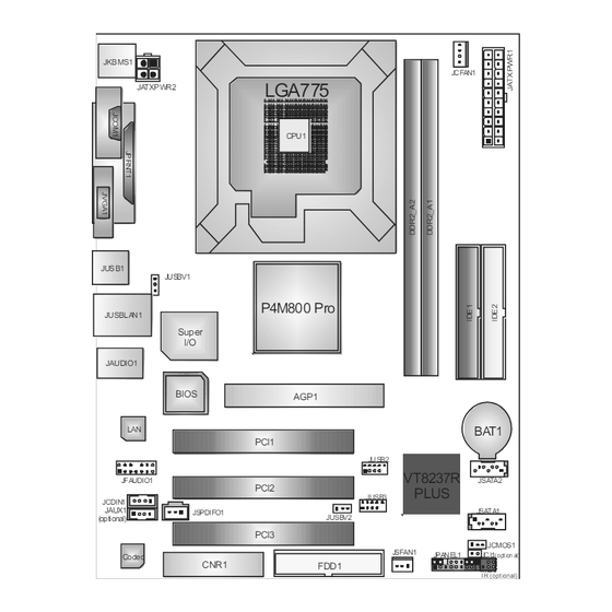
Page 6: Motherboard Layout
Motherboard Manual OT HERBOARD AYOUT JKBMS1 JCFAN1 LGA775 JA TXPWR2 CPU1 JUSB1 JUS BV1 P4M800 Pro JUSBLA N1 Super JAUDIO1 BIOS AGP1 BAT1 PCI1 JUSB2 VT8237R JFAUDIO1 JSATA2 PCI2 PLUS JUSB3 JCDIN 1 JAUX1 JSATA1 JSPDIFO1 JUSBV2 (optional) PCI3 JCMOS1... -
Page 7: Chapter 2: Hardware Installation
P4M800 Pro-M7 CHAPTER 2: HARDWARE INSTALLATION (CPU) NST ALLING ENT RAL ROCESSING Special Notice: Remove Pin Cap before installation, and make good preservation for future use. When the CPU is removed, cover the Pin Cap on the empty socket to ensure pin legs won’t be damaged. - Page 8 Motherboard Manual Step 2: Look for the triangular cut edge on socket, and the golden dot on CPU should point forwards this triangular cut edge. The CPU will fit only in the correct orientation. Step 2-1: Step 2-2: Step 3: Hold the CPU down firmly, and then lower the lever to locked position to complete the installation.
-
Page 9: Fan Headers
P4M800 Pro-M7 FAN H EADERS These fan headers support cooling-fans built in the computer. The fan cable and connector may be different according to the fan manufacturer. Connect the fan cable to the connector while matching the black wire to pin#1. -
Page 10: Installing System Memory
Motherboard Manual NST ALLING YST EM EMORY A. Memory Modules Unlock a DIMM slot by pressing the retaining clips outward. Align a DIMM on the slot such that the notch on the DIMM matches the break on the Slot. Insert the DIMM vertically and firmly into the slot until the retaining chip snap back in place and the DIMM is properly seated. -
Page 11: Connectors And Slots
P4M800 Pro-M7 ONNECT ORS AND LOT S FDD1: Floppy Disk Conne ctor The motherboard prov ides a standard floppy disk connector that supports 360K, 720K, 1.2M, 1.44M and 2.88M floppy disk ty pes. This connector supports the prov ided f loppy drive ribbon cables. - Page 12 Motherboard Manual PCI1~PCI3: Pe riphe ral Component Interconne ct Slots This motherboard is equipped with 3 standard PCI slots. PCI stands f or Peripheral Component Interconnect, and it is a bus standard for expansion cards. This PCI slot is designated as 32 bits. PCI1 PCI2 PCI3...
-
Page 13: Chapter 3: Headers & Jumpers Setup
P4M800 Pro-M7 CHAPTER 3: HEADERS & JUMPERS SETUP OW T O ET UP UMPERS The illustration shows how to set up jumpers. When the jumper cap is placed on pins, the jumper is “close”, if not, that means the jumper is “open”. - Page 14 Motherboard Manual JATXPWR1: ATX Powe r Source Conne ctor This connector allows user to connect 20-pin power connector on the ATX power supply. Assignment Assignment +3.3V +3.3V -12V +3.3V Ground Ground PS_ON Ground Ground Ground Ground Ground PW_OK Standby Voltage +5V +12V JATXPWR2: ATX Powe r Source Conne ctor By connecting this connector, it will provide +12V to CPU power circuit.
- Page 15 P4M800 Pro-M7 JUSB2/JUSB3: He ade rs for USB 2.0 Ports at Front Panel This header allows user to connect additional USB cable on the PC f ront panel, and also can be connected with internal USB devices, like USB card reader.
- Page 16 Motherboard Manual JFAUDIO1: Front Panel Audio Heade r This header allows user to connect the front audio output cable with the PC f ront panel. It will disable the output on back panel audio connectors. Assignment Mic-in/Stereo MIC-in Ground Stereo MIC-in L Audio power Right line-out/ Speaker-out Right...
-
Page 17: Serial Ata Connectors
P4M800 Pro-M7 JCMO S1: Cle ar CMOS Heade r By placing the jumper on pin2-3, it allows user to restore the BIOS saf e setting and the CMOS data, please carefully f ollow the procedures to avoid damaging the motherboard. - Page 18 Motherboard Manual JSPDIFO1: Digital Audio-out Conne ctor This connector allows user to connect the PCI bracket SPDIF output header. Assignment SPDIF_OUT Ground JCI1: Chassis O pen Heade r (optional) This connector allows system to monitor PC case open status. If the signal has been triggered, it will record to the CMOS and show the message on next boot-up.
-
Page 19: Chapter 4: Raid Functions
P4M800 Pro-M7 CHAPTER 4: RAID FUNCTIONS PERAT ION YST EM Supports Windows XP Home/Prof essional Edition, and Windows 2000 Professional. RRAYS RAID supports the following types of RAID arrays: RAID 0: RAID 0 defines a disk striping scheme that improves disk read and write times for many applications. - Page 20 Motherboard Manual RAID 1: Every read and write is actually carried out in parallel across 2 disk drives in a RAID 1 array system. The mirrored (backup) copy of the data can reside on the same disk or on a second redundant drive in the array. RAID 1 provides a hot-standby copy of data if the active volume or drive is corrupted or becomes unavailable because of a hardware failure.
-
Page 21: Chapter 5: Useful Help
P4M800 Pro-M7 CHAPTER 5: USEFUL HELP RIVER NST ALLAT ION OT E After you installed your operating system, please insert the Fully Setup Driver CD into your optical drive and install the driver for better system performance. You will see the following window after you insert the CD The setup guide will auto detect your motherboard and operating system. -
Page 22: Award Bios Beep Code
BIOS contents are corrupted. In this Case, please follow the procedure below to restore the BIOS: 1. Make a bootable floppy disk. 2. Download the Flash Utility “AWDFLASH.exe” from the Biostar website: www.biostar.com.tw 3. Confirm motherboard model and download the respectively BIOS from Biostar website. - Page 23 P4M800 Pro-M7 B. CPU Overheated If the system shutdown automatically after power on system for seconds, that means the CPU protection function has been activated. When the CPU is over heated, the motherboard will shutdown automatically to avoid a damage of the CPU, and the system may not power on again.
-
Page 24: Troubleshooting
Motherboard Manual ROUBLESHOOT ING Probable Solution No power to the system at all Make sure power cable is Power light don’t illuminate, f an securely plugged in. inside power supply does not turn Replace cable. Contact technical support. Indicator light on key board does not turn on. -
Page 25: Chapter 6: Warpspeeder
P4M800 Pro-M7 WARPSPEEDER™ CHAPTER 6: NT RODUCT ION [WarpSpeeder™], a new powerful control utility, features three user-friendly functions including Overclock Manager, Overvoltage Manager, and Hardware Monitor. With the Overclock Manager, users can easily adjust the frequency they prefer or they can get the best CPU performance with just one click. The Overvoltage Manager, on the other hand, helps to power up CPU core voltage and Memory voltage. -
Page 26: Installation
Motherboard Manual NST ALLAT ION 1. Execute the setup execution file, and then the following dialog will pop up. Please click “Next” button and follow the default procedure to install. 2. When you see the following dialog in setup procedure, it means setup is completed. -
Page 27: Warpspeeder
P4M800 Pro-M7 6.4 W ™ PEEDER 1. Tray Icon: Whenever the Tray Icon utility is launched, it will display a little tray icon on the right side of Windows Taskbar. This utility is responsible for conveniently invoking [WarpSpeeder™] Utility. You can use the mouse by clicking the left button in order to invoke [WarpSpeeder™] directly from the little tray icon or you can... - Page 28 Motherboard Manual 2. Main Panel If you click the tray icon, [WarpSpeeder™] utility will be invoked. Please refer to the following figure; the utility’s first window you will see is Main Panel. Main Panel contains fe ature s as follows: a.
- Page 29 P4M800 Pro-M7 3. Voltage Panel Click the Voltage button in Main Panel, the button will be highlighted and the Voltage Panel will slide out to up as the following figure. In this panel, you can decide to increase CPU core voltage and Memory voltage or not.
- Page 30 Motherboard Manual 4. Overclock Panel Click the Overclock button in Main Panel, the button will be highlighted and the Overclock Panel will slide out to left as the following figure. O ve rclock Panel contains the these features: a. “–3MHz button”, “-1MHz button”, “+1MHz button”, and “+3MHz button”: provide user the ability to do real-time overclock adjustment.
- Page 31 P4M800 Pro-M7 “Auto-overclock button”: User can click this button and [WarpSpeeder™] will set the best and stable performance and frequency automatically. [WarpSpeeder™] utility will execute a series of testing until system fail. Then system will do fail-safe reboot by using Watchdog function. After reboot, the [WarpSpeeder™] utility will restore to the hardware default...
- Page 32 Motherboard Manual 6. About Panel Click the “about” button in Main Panel, the button will be highlighted and the About Panel will slide out to up as the following figure. In this panel, you can get model name and detail information in hints of all the chipset that are related to overclocking.
- Page 33 P4M800 Pro-M7 This page is intentionally left blank...
-
Page 34: Appendencies: Spec In Other Language
Memory 64 Technology *It is recommende d to use processors with 95W power consumption. 533 / 800 / 1066 MHz VIA P4M800 PRO Chipsatz VIA VT8237R+ Grafik Integrierter UniC hrome Pro C hipsatz Max. 64MB gemeinsam benutzter Videospeicher ITE IT8705AF Umgebungskontrolle, Bietet die häufi g verwe ndete n alte n... - Page 35 201 mm (B) X 244 mm (L) ße. Sonderfunkt Unterstützt RAID 0 / 1 ionen Biostar behält sich das Recht v or, ohne OS-Unterst Windows 2K / XP Ankündigung die Unterstützung für ei n ützung Betriebssystem hinzuzufügen oder zu entferne n.
-
Page 36: France
(Seulement pour Ver 2.0 / 8.0) mémoire étendue 64 *It is recommende d to use processors with 95W power consumption. Bus frontal 533 / 800 / 1066 MHz VIA P4M800 PRO Chipset VIA VT8237R+ Graphi que Integré dans l a chipset U niChrome Mémoire vidé... - Page 37 201 mm (l) X 244 mm (H) carte Fonctionna Prise en c harge RAID 0 / 1 lités spéciales Support Biostar se réserve le droit d'ajo uter o u de Windows 2K / XP supprimer le support de SE av ec ou sans préavis.
-
Page 38: Italian
Extende d Memor y 64 *It is recommende d to use processors with 95W power consumption. 533 / 800 / 1066 MHz VIA P4M800 PRO Chipset VIA VT8237R+ Grafica Integrata nel Chi pset UniC hrome Pr o La memoria vi deo co ndivisa massima è di 64MB ITE IT8705AF Funzioni di co ntrollo dell’ambiente:... - Page 39 201 mm (larghezza) x 244 mm i scheda (altezza) Caratterist iche Supporto RAID 0 / 1 speciali Sistemi Biostar si riserva il diritto di aggiungere o operativi Windows 2K / XP rimuovere il supporto di qualsiasi sistema supportati operativo se nza pre avviso.
-
Page 40: Spanish
Tecnolo gía Extended M emory 64 *It is recommende d to use processors with 95W power consumption. 533 / 800 / 1066 MHz Conjunto VIA P4M800 PRO de chips VIA VT8237R+ Integrados en el conjunto de chips Gráficos Memoria máxima de ví deo compartida de 64MB... - Page 41 201mm. (A) X 244 Mm. (H) la placa Funciones Admite RAID 0 / 1 especiales Soporte de Biostar se reserva el derecho de aña dir o r etirar el sistema Windows 2K / XP soporte de cualquier SO con o sin aviso previo. operativo...
-
Page 42: Portuguese
Ver 2.0 / 8.0) / Exte nded Memory 64 *It is recommende d to use processors with 95W power consumption. 533 / 800 / 1066 MHz VIA P4M800 PRO Chipset VIA VT8237R+ Placa Integrada no chipset U niChrome Pro Memória de víde o máxima partilha da: 64 MB... - Page 43 Característ Suporta as funções RAID 0 / 1 icas especiais Sistemas A Biostar reserva-se o direito de adicionar ou operativos Windows 2K / XP remover suporte par a qual quer sistema operativo suportado com ou sem aviso pré vio.
-
Page 44: Polish
Ver 2.0 / 8.0) 64 Technology *It is recommende d to use processors with 95W power consumption. 533 / 800 / 1066 MHz VIA P4M800 PRO Chipset VIA VT8237R+ Zintegrowana w chipsecie U niChrome Maks. wielkość współdzielonej pamięci video... - Page 45 Gniazdo audio Wymiary 201 mm (S) X 244 mm (W) płyty Funkcje Obsługa RAID 0 / 1 specjalne Obsluga Biostar zastrzega sobie prawo do dawania lub systemu Windows 2K / XP odwoływania obsługi dowolnego systemu operacyjn operacyjnego bez powiadomie nia.
-
Page 46: Russian
/ Exte nded Memory 64 Technol ogy *It is recommende d to use processors with 95W power consumption. 533 / 800 / 1066 МГц Набор VIA P4M800 PRO микросхе VIA VT8237R+ м Встроенная в набо р м икросхем Максимальная совмес тно используемая видео... - Page 47 техническ Подде ржка RAID 0 / 1 ие харак тери стики Biostar сохраня ет за собо й прав о добав лять Подде ржк Windows 2K / XP или уда лять сре дства обес пече ния для OS с а OS...
-
Page 48: Arabic
*It is recommende d to use processors with 95W power consumption. اﻷﻡﺎﻡﻲ اﻟﻨﺎﻗﻞ ﻡﻴﺠﺎ هﺮﺕﺰ 6601 / 008 / 335 ﺕﺮدد اﻟﺠﺎﻥﺒﻲ VIA P4M800 PRO اﻟﺸﺮاﺋﺢ ﻡﺠﻤﻮﻋﺔ VIA VT8237R+ ﻡﺪﻡﺠﺔ ﻓﻲ رﻗﺎﺋﻖUniChr ome Pr o ﻡﻴﺠﺎ ﺑﺎﻳﺖ46أﻗﺼﻰ ﺳﻌﺔ ﻟﺬاآﺮة اﻟﻔﻴﺪﻳﻮ اﻟﻤﺸﺘﺮآﺔ ﺑﻄﺎﻗﺔ اﻟﺮﺳﻮﻡﺎت... - Page 49 P4M800 Pro-M7 اﻟﻤﻮاﺻﻔﺎت ﻋﺪد ﻓﺘﺤﺔ ﻋﺪد ﻡﻨﻔﺬ ﻡﺤﺮك أﻗﺮاص ﻡﺮﻥﺔ اﻟﻤﺮﻥﺔ ﻟﻸﻗﺮا ص ﻡﺤﺮآﻴﻦ ﻳﺪﻋﻢ ﻋﺪد ﻡﻨﻔﺬ ﺰة أﺝﻬ ﻡﻦ اﺙﻨﻴﻦ ﻡﻨﻔﺬ آﻞ ﻳﺪﻋﻢ SATA ﻋﺪد SATA ﻡﻨﻔﺬ أﺝﻬﺰة ﻡﻦ واﺣﺪ ﻡﻨﻔﺬ آﻞ ﻳﺪﻋﻢ ﻋﺪد ﻡﻨﻔﺬ اﻟﻠﻮﺣﺔ اﻷﻡﺎﻡﻴﺔ اﻷﻡﺎﻡﻴﺔ اﻟﻠﻮﺣﺔ...
-
Page 50: Japanese
Enha nced Intel SpeedStep® / Extended Memory 8.0 のみ) 64 Technology をサポートします *It is recommende d to use processors with 95W power consumption. 533 / 800 / 1066 MHz VIA P4M800 PRO チップセッ VIA VT8237R+ ト グラフィッ UniChrome Pro チップセットに統合... - Page 51 P4M800 Pro-M7 仕様 各コネクタは2つのフロッピードライブをサポートし フロッピーコネクタ ます IDEコネクタ 各コネクタは2つのIDEデバイスをサポートします SATAコネクタ 各コネクタは1つのSATAデバイスをサポートします フロントパネルコネクタ フロントパネル機能をサポートします フロントオーディオコネクタ フロントパネルオーディオ機能をサポートします CDインコネクタ CDオーディオイン機能をサポートします S/PDIFアウトコネクタ デジタルオーディオアウト機能をサポートします オンボード CPUファンヘッダ CPUファン電源装置(スマートファン機能を搭載) コネクタ システムファンヘッダ システムファン電源装置 シャーシオープンヘッダ シャーシ侵入検出機能 (オプション) CMOSクリアヘッダ 各コネクタは2つのフロントパネルUSBポートをサポ USBコネクタ ートします 電源コネクタ(20ピン) 電源コネクタ(4ピン) PS/2キーボード PS/2マウス シリアルポート 背面パネル プリンタポート VGAポート LANポート...
Need help?
Do you have a question about the P4M800 and is the answer not in the manual?
Questions and answers