Table of Contents
Advertisement
P4M800-M7 & P4M800-M7 A
FCC Information and Copyright
This equipment has been tested and found to comply with the limits of a Class
B digital device, pursuant to Part 15 of the FCC Rules. These limits are designed
to provide reasonable protection against harmful interference in a residential
installation. This equipment generates, uses and can radiate radio frequency
energy and, if not installed and used in accordance with the instructions, may
cause harmful interference to radio communications. There is no guarantee
that interference will not occur in a particular installation.
The vendor makes no representations or warranties with respect to the
contents here and specially disclaims any implied warranties of merchantability
or fitness for any purpose. Further the vendor reserves the right to revise this
publication and to make changes to the contents here without obligation to
notify any party beforehand.
Duplication of this publication, in part or in whole, is not allowed without first
obtaining the vendor's approval in writing.
The content of this user's manual is subject to be changed without notice and
we will not be responsible for any mistakes found in this user's manual. All the
brand and product names are trademarks of their respective companies.
i
Advertisement
Table of Contents

Related Manuals for Biostar P4M800-M7 A


Summary of Contents for Biostar P4M800-M7 A
- Page 1 P4M800-M7 & P4M800-M7 A FCC Information and Copyright This equipment has been tested and found to comply with the limits of a Class B digital device, pursuant to Part 15 of the FCC Rules. These limits are designed to provide reasonable protection against harmful interference in a residential installation.
-
Page 2: Table Of Contents
Chapter 1: Introduction ...1 Features ...1 Package List ...3 Layout: P4M800-M7...4 Components: P4M800-M7 ...5 Layout: P4M800-M7 A (Rev 1.0) ...6 Components: P4M800-M7 A (Rev 1.0) ...7 Layout: P4M800-M7 A (Rev 7.0) ...8 Components: P4M800-M7 A (Rev 7.0) ...9 Chapter 2: Hardware Installation ...10... -
Page 3: Product Overview And Features
Chip: ITE IT8705AF Provides the most commonly used legacy super I/O functionality. Environment Control initiatives: H/W Monitor, Fan Speed Controller, ITE “Smart Guardian” function. VIA P4M800CE (for P4M800-M7 A v1.0 and v7.0). DDR Module 128MB/256MB/512MB/1GB *1 128MB/256MB/512MB/1GB *1 Total Memory Size... - Page 4 Onboard IDE Support 4 IDE disk drives. Supports PIO mode 5, Bus Master, and Ultra DMA 33/66/100/133 function. Chip: RealTek RTL8100C (for P4M800-M7/P4M800-M7 A v1.0) VIA VT6103L (for P4M800-M7 A v 7.0) Supports 10/100 Mb/s auto-negotiation operation. Half/Full duplex capability.
-
Page 5: Package List
P4M800-M7 & P4M800-M7 A 2 IDE connectors support 4 hard disk devices. 2 serial ATA connectors support 2 SATA devices. Rear Side Connectors 4 USB 2.0 ports. 1 VGA port. 1 serial port. 1 parallel port. 1 RJ-45 LAN jack. -
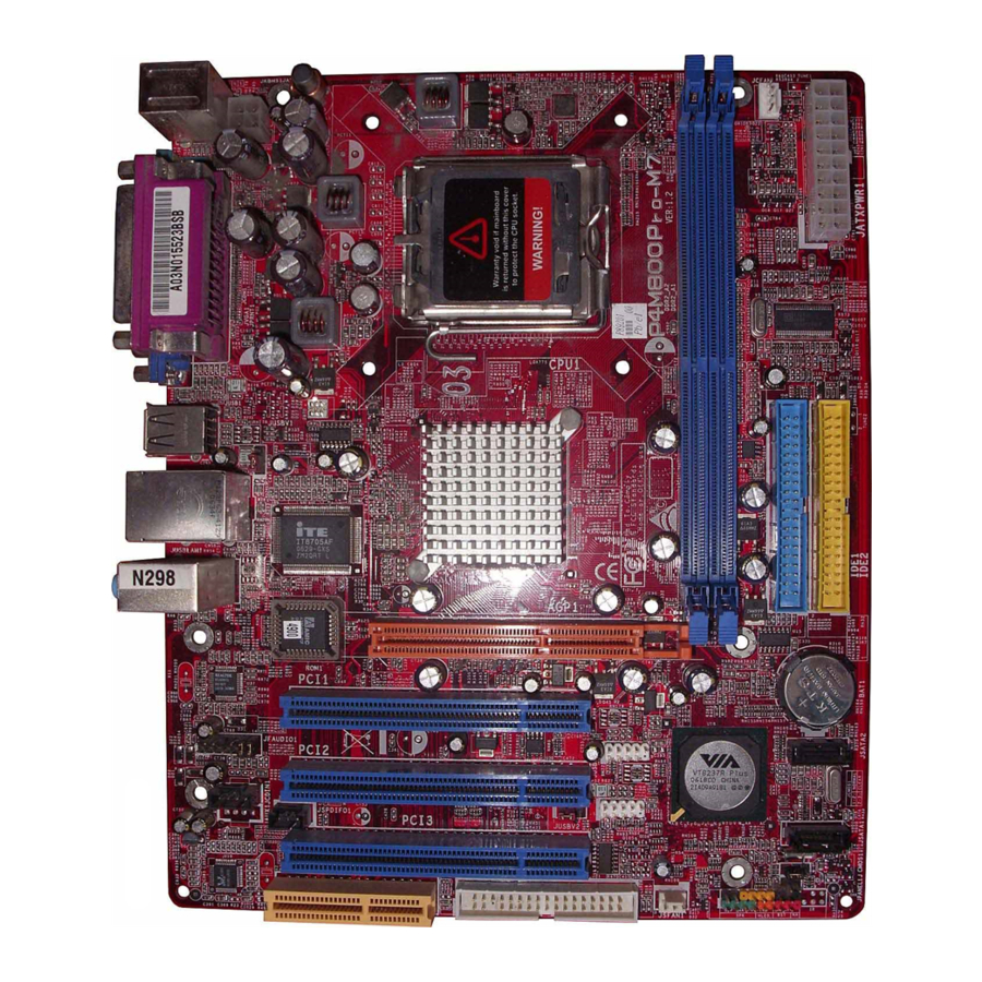
Page 6: Layout: P4M800-M7
P4M800-M7 & P4M800-M7 A : P4M800-M7 AYOUT JKBMS1 LGA775 JATXPWR2 JCOM1 JVGA1 JUSB1 JUSBV1 JUSBLAN1 Super JAUDIO BIOS PCI1 RTL8100C PCI2 JAUDIO1 JSPDIFO1 (optional) JCDIN1 PCI3 Codec CNR1 Note: ■ represents the 1 pin. CPU1 P4M800CD AGP1 JUSB3 VT8237R JUSB4... -
Page 7: Components: P4M800-M7
P4M800-M7 & P4M800-M7 A : P4M800-M7 OMPONENTS Super BIOS Codec JATXPWR2: ATX power connector. Back panel connectors (rear side). JUSBV1: USB power header for JKBMS1, JUSB1, and JUSBLAN1. JAUDIO1: Front panel audio out header. JCDIN1: CD-ROM audio in connector. P. -
Page 8: Layout: P4M800-M7 A (Rev 1.0)
P4M800-M7 & P4M800-M7 A : P4M800-M7 A (R AYOUT JKBMS1 LGA775 JATXPWR2 JUSB1 JUSBV1 JUSBLAN1 P4M800CE Super JAUDIO BIOS PCI1 RTL8100C PCI2 JAUDIO1 JCDIN1 JSPDIFO1 JAUX1 (optional) (optional) PCI3 Codec CNR1 Note: ■ represents the 1 pin. 1.0) JCFAN1 CPU1... -
Page 9: Components: P4M800-M7 A (Rev 1.0)
P4M800-M7 & P4M800-M7 A : P4M800-M7 A (R OMPONENTS JATXPWR2: ATX power connector. Back panel connectors (rear side). JUSBV1: USB power header for back panel. JAUDIO1: Front panel audio out header. JSPDIFO1 (optional): Digital audio out connector. JCDIN1: CD-ROM audio in connector. Q. -
Page 10: Layout: P4M800-M7 A (Rev 7.0)
P4M800-M7 & P4M800-M7 A : P4M800-M7 A (R AYOUT JKBMS1 LGA775 JATXPWR2 JUSB1 JUSBV1 JUSBLAN1 P4M800CE Super JAUDIO BIOS PCI1 VT6103L PCI2 JAUDIO1 JCDIN1 JSPDIFO1 JAUX1 (optional) (optional) PCI3 Codec CNR1 Note: ■ represents the 1 pin. 7.0) JCFAN1 CPU1... -
Page 11: Components: P4M800-M7 A (Rev 7.0)
P4M800-M7 & P4M800-M7 A : P4M800-M7 A (R OMPONENTS JATXPWR2: ATX power connector. Back panel connectors (rear side). JUSBV1: USB power header for back panel. JAUDIO1: Front panel audio out header. JSPDIFO1 (optional): Digital audio out connector. JCDIN1: CD-ROM audio in connector. Q. -
Page 12: Chapter 2: Hardware Installation
P4M800-M7 & P4M800-M7 A CHAPTER 2: HARDWARE INSTALLATION ENTRAL ROCESSING Special Notice: Remove Pin Cap before installation, and make good preservation for future use. When the CPU is removed, cover the Pin Cap on the empty socket to ensure pin legs won’t be damaged. -
Page 13: Fan Headers
P4M800-M7 & P4M800-M7 A Step 2-2: Step 3: Hold the CPU down firmly, and then close the lever to complete the installation. Step 4: Put the CPU Fan on the CPU and buckle it. Connect the CPU FAN power cable to the JCFAN1. This completes the installation. -
Page 14: Memory Module Installation
P4M800-M7 & P4M800-M7 A EMORY ODULE NSTALLATION Unlock a DIMM slot by pressing the retaining clips outward. Align a DIMM on the slot such that the notch on the DIMM matches the break on the Slot. Insert the DIMM vertically and firmly into the slot until the retaining chip snap back in place and the DIMM is properly seated. -
Page 15: Connectors And Slots
The first hard drive should always be connected to IDE1. This motherboard is equipped with 3 standard PCI slots. PCI stands for Peripheral Component Interconnect, and it is a bus standard for expansion cards. This PCI slot is designated as 32 bits. -
Page 16: Chapter 3: Headers & Jumpers Setup
“JUSBV1/JUSBV2” jumper cap should be placed on Pin 2-3. JUSB3/JUSB4: Front USB Headers This motherboard provides 2 USB 2.0 headers, which allows user to connect additional USB cable on the PC front panel, and also can be connected with internal USB devices, like USB card reader. -
Page 17: Front Panel Audio Header
P4M800-M7 & P4M800-M7 A JATXPWR1/PATXPWR2: Power Connectors JATXPWR1: This connector allows user to connect with 20-pin power connector on the ATX power supply. JATXPWR2: By connecting this connector, it will provide +12V to CPU power circuit. Assignment +3.3V +3.3V Ground... - Page 18 P4M800-M7 & P4M800-M7 A JCDIN1: CD-ROM Audio-in Connector This connector allows user to connect the audio source from the veriaty devices, like CD-ROM, DVD-ROM, PCI sound card, PCI TV turner card etc.. JCDIN1 JSPDIFO1: Digital Audio-out Connector (optional) This connector allows user to connect the PCI bracket SPDIF output header.
-
Page 19: Chassis Open Header
P4M800-M7 & P4M800-M7 A JCI1: Chassis Open Header This connector allows system to monitor PC case open status. If the signal has been triggered, it will record to the CMOS and show the message on next boot-up. JCI1 JPANEL1: Front Panel Header This 24-pin connector includes Power-on, Reset, HDD LED, Power LED, Sleep button, speaker and IrDA Connection. -
Page 20: Chapter 4: Useful Help
BIOS contents are corrupted. In this Case, please follow the procedure below to restore the BIOS: 1. Make a bootable floppy disk. 2. Download the Flash Utility “AWDFLASH.exe” from the Biostar website: www.biostar.com.tw 3. Confirm motherboard model and download the respectively BIOS from Biostar website. - Page 21 P4M800-M7 & P4M800-M7 A If the system shutdown automatically after power on system for seconds, that means the CPU protection function has been activated. When the CPU is over heated, the motherboard will shutdown automatically to avoid a damage of the CPU, and the system may not power on again.
-
Page 22: Troubleshooting
P4M800-M7 & P4M800-M7 A ROUBLESHOOTING Probable No power to the system at all Power light don’t illuminate, fan inside power supply does not turn Indicator light on keyboard does not turn on. System inoperative. Keyboard lights are on, power indicator lights are lit, and hard drive is spinning. -
Page 23: Chapter 5: Warpspeeder
P4M800-M7 & P4M800-M7 A CHAPTER 5: WARPSPEEDER™ NTRODUCTION [WarpSpeeder™], a new powerful control utility, features three user-friendly functions including Overclock Manager, Overvoltage Manager, and Hardware Monitor. With the Overclock Manager, users can easily adjust the frequency they prefer or they can get the best CPU performance with just one click. The Overvoltage Manager, on the other hand, helps to power up CPU core voltage and Memory voltage. -
Page 24: Installation
Tray Icon utility and [WarpSpeeder™] utility will be automatically and immediately launched after you click “Finish” button. Usage: The following figures are just only for reference, the screen printed in this user manual will change according to your motherboard on hand. -
Page 25: Warpspeeder™] Includes 1 Tray Icon And 5 Panels
P4M800-M7 & P4M800-M7 A ™] PEEDER INCLUDES Whenever the Tray Icon utility is launched, it will display a little tray icon on the right side of Windows Taskbar. This utility is responsible for conveniently invoking [WarpSpeeder™] Utility. You can use the mouse by clicking the left button in order to invoke [WarpSpeeder™] directly from the little tray icon or you can... - Page 26 P4M800-M7 & P4M800-M7 A If you click the tray icon, [WarpSpeeder™] utility will be invoked. Please refer to the following figure; the utility’s first window you will see is Main Panel. Main Panel contains features as follows: Display the CPU Speed, CPU external clock, Memory clock, AGP clock, and PCI clock information.
- Page 27 P4M800-M7 & P4M800-M7 A Click the Voltage button in Main Panel, the button will be highlighted and the Voltage Panel will slide out to up as the following figure. In this panel, you can decide to increase CPU core voltage and Memory voltage or not.
- Page 28 P4M800-M7 & P4M800-M7 A Click the Overclock button in Main Panel, the button will be highlighted and the Overclock Panel will slide out to left as the following figure. Overclock Panel contains the these features: “–3MHz button”, “-1MHz button”, “+1MHz button”, and “+3MHz button”: provide user the ability to do real-time overclock...
- Page 29 P4M800-M7 & P4M800-M7 A “Auto-overclock button”: User can click this button and [WarpSpeeder™] will set the best and stable performance and frequency automatically. [WarpSpeeder™] utility will execute a series of testing until system fail. Then system will do fail-safe reboot by using Watchdog function. After reboot, the [WarpSpeeder™] utility will restore to the hardware default...
- Page 30 P4M800-M7 & P4M800-M7 A Click the “about” button in Main Panel, the button will be highlighted and the About Panel will slide out to up as the following figure. In this panel, you can get model name and detail information in hints of all the chipset that are related to overclocking.
- Page 31 P4M800-M7 & P4M800-M7 A Note: Because the overclock, overvoltage, and hardware monitor features are controlled by several separate chipset, [WarpSpeeder™] divide these features to separate panels. If one chipset is not on board, the correlative button in Main panel will be disabled, but will not interfere other panels’...
Need help?
Do you have a question about the P4M800-M7 A and is the answer not in the manual?
Questions and answers