Table of Contents
Advertisement
Available languages
Available languages
P4M900-M7 SE/P4M890-M7 TE
Setup Manual
FCC Information and Copyright
This equipment has been tested and found to comply with the limits of a Class
B digital device, pursuant to Part 15 of the FCC Rules. These limits are designed
to provide reasonable protection against harmful interference in a residential
installation. This equipment generates, uses, and can radiate radio frequency
energy and, if not installed and used in accordance with the instructions, may
cause harmful interference to radio communications. There is no guarantee
that interference will not occur in a particular installation.
The vendor makes no representations or warranties with respect to the
contents here and specially disclaims any implied warranties of merchantability
or fitness for any purpose. Further the vendor reserves the right to revise this
publication and to make changes to the contents here without obligation to
notify any party beforehand.
Duplication of this publication, in part or in whole, is not allowed without first
obtaining the vendor's approval in writing.
The content of this user's manual is subject to be changed without notice and
we will not be responsible for any mistakes found in this user's manual. All the
brand and product names are trademarks of their respective companies.
Advertisement
Table of Contents

Related Manuals for Biostar P4M890-M7 TE


Summary of Contents for Biostar P4M890-M7 TE
- Page 1 P4M900-M7 SE/P4M890-M7 TE Setup Manual FCC Information and Copyright This equipment has been tested and found to comply with the limits of a Class B digital device, pursuant to Part 15 of the FCC Rules. These limits are designed to provide reasonable protection against harmful interference in a residential installation.
-
Page 2: Table Of Contents
Table of Contents Chapter 1: Introduction .......... 3 Before You Start ................3 Package Checklist ................3 Motherboard Features ..............4 Rear Panel Connectors ..............5 Motherboard Layout ................ 6 Chapter 2: Hardware Installation ......7 Installing Central Processing Unit (CPU) ........7 Fan Headers .................. -
Page 3: Chapter 1: Introduction
P4M900-M7 SE/P4M890-M7 TE CHAPTER 1: INTRODUCTION EFORE TART Thank you for choosing our product. Before you start installing the motherboard, please make sure you follow the instructions below: Prepare a dry and stable working environment with sufficient lighting. Always disconnect the computer from power outlet ... -
Page 4: Motherboard Features
Motherboard Manual OTHERBOARD EATURES P4M900-M7 SE P4M890-M7 TE LGA 775 LGA 775 Intel Core2Duo/ Pentium 4 / Pentium D / Intel Core2Duo/ Pentium 4 / Pentium D / Celeron D / Celeron 4xx processor up to 3.8 Celeron D / Celeron 4xx processor up to 3.8... -
Page 5: Rear Panel Connectors
RAID 0 / 1 support Feature Windows 2000 / XP / VISTA Windows 2000 / XP Biostar Reserves the right to add or remove Biostar Reserves the right to add or remove Support support for any OS with or without notice. -
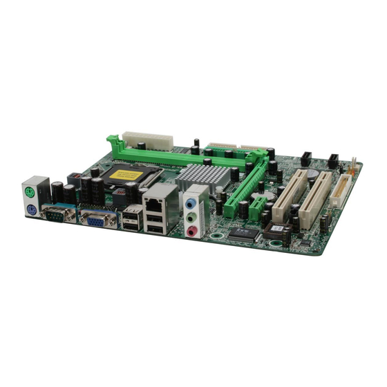
Page 6: Motherboard Layout
Motherboard Manual OTHERBOARD AYOUT JCFAN1 JKBMS1 LGA775 CPU1 JATXPWR1 JPRNT1 JUSB1 JATXPWR2 P4M900 JUSBLAN1 P4M890 JAUDIO1 PCI-EX16 BAT1 Super PCI-EX1_1 BIOS JSATA2 JUSB2 PCI1 VT8237A JSATA1 JCDIN1 JUSB3 PCI2 JCMOS1 Codec JAUDIOF1 FDD1 JSFAN1 JPANEL1 Note: ■ rep resen ts th e 1 pin. -
Page 7: Chapter 2: Hardware Installation
P4M900-M7 SE/P4M890-M7 TE CHAPTER 2: HARDWARE INSTALLATION (CPU) NSTALLING ENTRAL ROCESSING Special Notice: Remove Pin Cap before installation, and make good preservation for future use. When the CPU is removed, cover the Pin Cap on the empty socket to ensure pin legs won’t be damaged. - Page 8 Motherboard Manual Step 2: Look for the triangular cut edge on socket, and the golden dot on CPU should point forwards this triangular cut edge. The CPU will fit only in the correct orientation. Step 2-1: Step 2-2: Step 3: Hold the CPU down firmly, and then lower the lever to locked position to complete the installation.
-
Page 9: Fan Headers
P4M900-M7 SE/P4M890-M7 TE EADERS These fan headers support cooling-fans built in the computer. The fan cable and connector may be different according to the fan manufacturer. Connect the fan cable to the connector while matching the black wire to pin#1. -
Page 10: Installing System Memory
Motherboard Manual NSTALLING YSTEM EMORY A. Memory Modules Unlock a DIMM slot by pressing the retaining clips outward. Align a DIMM on the slot such that the notch on the DIMM matches the break on the Slot. Insert the DIMM vertically and firmly into the slot until the retaining chip snap back in place and the DIMM is properly seated. -
Page 11: Connectors And Slots
P4M900-M7 SE/P4M890-M7 TE ONNECTORS AND LOTS FDD1: Floppy Disk Connector The motherboard provides a standard floppy disk connector that supports 360K, 720K, 1.2M, 1.44M and 2.88M floppy disk types. This connector supports the provided floppy drive ribbon cable. IDE1/IDE2: Hard Disk Connectors The motherboard has a 32-bit Enhanced PCI IDE Controller that provides PIO Mode 0~4, Bus Master, and Ultra DMA 33/66/100/133 functionality. - Page 12 Motherboard Manual PCI-EX16: PCI-Express x16 Slot PCI-Express 1.0a compliant. Maximum theoretical realized bandwidth of 4GB/s simultaneously per direction, for an aggregate of 8GB/s totally. PCI-EX1_1: PCI-Express x1 Slot PCI-Express 1.0a compliant. Data transfer bandwidth up to 250MB/s per direction; 500MB/s in total. PCI-Express supports a raw bit-rate of 2.5Gb/s on the data pins.
-
Page 13: Chapter 3: Headers & Jumpers Setup
P4M900-M7 SE/P4M890-M7 TE CHAPTER 3: HEADERS & JUMPERS SETUP OW TO ETUP UMPERS The illustration shows how to set up jumpers. When the jumper cap is placed on pins, the jumper is “close”, if not, that means the jumper is “open”. - Page 14 Motherboard Manual ATX Power Source Connector: JATXPWR1 JATXPWR1 allows user to connect 24-pin power connector on the ATX power supply. Assignment Assignment +3.3V +3.3V -12V +3.3V Ground Ground PS_ON Ground Ground Ground Ground Ground PW_OK Standby Voltage+5V +12V +12V Ground +3.3V JATXPWR2: ATX Power Source Connector By connecting this connector, it will provide +12V to CPU power circuit.
-
Page 15: Headers For Usb 2.0 Ports At Front Panel
P4M900-M7 SE/P4M890-M7 TE JUSB2/JUSB3: Headers for USB 2.0 Ports at Front Panel This header allows user to connect additional USB cable on the PC front panel, and also can be connected with internal USB devices, like USB card reader. Assignment... -
Page 16: Clear Cmos Procedures
Motherboard Manual JCDIN1: CD-ROM Audio-in Connector This connector allows user to connect the audio source from the variaty devices, like CD-ROM, DVD-ROM, PCI sound card, PCI TV turner card etc. Assignment Left Channel Input Ground Ground Right Channel Input JCMOS1: Clear CMOS Header By placing the jumper on pin2-3, it allows user to restore the BIOS safe setting and the CMOS data, please carefully follow the procedures to avoid damaging the motherboard. - Page 17 P4M900-M7 SE/P4M890-M7 TE JPRNT1: Printer Port Connector This header allows you to connector printer on the PC. Assignment Assignment -Strobe Ground -ALF Data 6 Data 0 Ground -Error Data 7 Data 1 Ground -Init -ACK Data 2 Ground -Scltin Busy...
-
Page 18: Chapter 4: Raid Functions
Motherboard Manual CHAPTER 4: RAID FUNCTIONS PERATION YSTEM Supports Windows XP Home/Professional Edition, and Windows 2000 Professional. RRAYS RAID supports the following types of RAID arrays: RAID 0: RAID 0 defines a disk striping scheme that improves disk read and write times for many applications. - Page 19 P4M900-M7 SE/P4M890-M7 TE RAID 1: Every read and write is actually carried out in parallel across 2 disk drives in a RAID 1 array system. The mirrored (backup) copy of the data can reside on the same disk or on a second redundant drive in the array.
-
Page 20: Chapter 5: Useful Help
Motherboard Manual CHAPTER 5: USEFUL HELP RIVER NSTALLATION After you installed your operating system, please insert the Fully Setup Driver CD into your optical drive and install the driver for better system performance. You will see the following window after you insert the CD The setup guide will auto detect your motherboard and operating system. -
Page 21: Award Bios Beep Code
P4M900-M7 SE/P4M890-M7 TE BIOS B WARD Beep Sound Meaning One long beep followed by two short Video card not found or video card beeps memory bad High-low siren sound CPU overheated System will shut down automatically One Short beep when system boot-up No error found during POST... -
Page 22: Troubleshooting
Motherboard Manual ROUBLESHOOTING Probable Solution No power to the system at all Make sure power cable is Power light don’t illuminate, fan securely plugged in. inside power supply does not turn Replace cable. Contact technical support. Indicator light on keyboard does not turn on. -
Page 23: Chapter 6: Warpspeeder™ Iii
P4M900-M7 SE/P4M890-M7 TE WARPSPEEDER™ III CHAPTER 6: NTRODUCTION [WarpSpeeder™ III], a new powerful control utility, features three user-friendly functions including Overclock Manager, Overvoltage Manager, and Hardware Monitor. With the Overclock Manager, users can easily adjust the frequency they prefer or they can get the best CPU performance with just one click. The Overvoltage Manager, on the other hand, helps to power up CPU core voltage and Memory voltage. -
Page 24: Installation
Motherboard Manual NSTALLATION 1. Execute the setup execution file, and then the following dialog will pop up. Please click “Next” button and follow the default procedure to install. 2. When you see the following dialog in setup procedure, it means setup is completed. -
Page 25: Warpspeeder™ Iii
P4M900-M7 SE/P4M890-M7 TE 6.4 W ™ III PEEDER 1. Desktop Icon: After the [WarpSpeeder™ III] has been installed, a [WarpSpeeder™ III] icon will appear on the desktop, just like the icon shown below. Now you can launch the [WarpSpeeder™ III] utility simply by double-clicking the desktop icon. - Page 26 Motherboard Manual 3. Overclock/Overvoltage Panel Click the Overclock/Overvoltage button in the Main Panel, the button will be highlighted and the Overclock/Overvoltage Panel will show up as the following figure. As you can see, the Overclock Panel is on the right side, and the Overvoltage Panel is on the left side.
- Page 27 P4M900-M7 SE/P4M890-M7 TE Overclock Panel contains these features: a. “Auto-Overclock”: User can click this button and [WarpSpeeder™ III] will set the best and stable performance and frequency automatically. A warning dialog as below will show up to notify you that the system may become unstable, click on “OK”...
- Page 28 Motherboard Manual Overvoltage Panel contains these features: a. “CPU Voltage”: This function allows user to adjust CPU voltage. Click on “+” to increase or “-“ to decrease the CPU voltage. b. “Memory Voltage”: This function allows user to adjust Memory voltage. Click on “+” to increase or “-“...
- Page 29 P4M900-M7 SE/P4M890-M7 TE 5. About Panel Click the “about” button in Main Panel, the button will be highlighted and the About Panel will show up as the following figure. In this panel, you can get model name and detail information in hints of all the chipset that are related to overclocking.
-
Page 30: Appendencies: Spec In Other Language
Motherboard Manual APPENDENCIES: SPEC IN OTHER LANGUAGE ERMAN P4M900-M7 SE P4M890-M7 TE LGA 775 LGA 775 Intel Core2Duo/ Pentium 4 / Pentium D / Intel Core2Duo/ Pentium 4 / Pentium D / Celeron D / Celeron 4xx Prozessoren mit Celeron D / Celeron 4xx Prozessoren mit... - Page 31 Unterstützt RAID 0 / 1 ionen Windows 2K / XP / VISTA Windows 2K / XP Biostar behält sich das Recht vor, ohne Biostar behält sich das Recht vor, ohne OS-Unterst Ankündigung die Unterstützung für ein Ankündigung die Unterstützung für ein ützung...
-
Page 32: France
Motherboard Manual RANCE P4M900-M7 SE P4M890-M7 TE LGA 775 LGA 775 Processeurs Intel Core2Duo/ Pentium 4 / Processeurs Intel Core2Duo/ Pentium 4 / Pentium D / Celeron D / Celeron 4xx jusqu'à Pentium D / Celeron D / Celeron 4xx jusqu'à... - Page 33 Windows 2K / XP / VISTA Windows 2K / XP Support Biostar se réserve le droit d'ajouter ou de Biostar se réserve le droit d'ajouter ou de supprimer le support de SE avec ou sans supprimer le support de SE avec ou sans préavis.
-
Page 34: Italian
Motherboard Manual TALIAN P4M900-M7 SE P4M890-M7 TE LGA 775 LGA 775 Processore Intel Core2Duo/ Pentium 4 / Processore Intel Core2Duo/ Pentium 4 / Pentium D / Celeron D / Celeron 4xx fino a Pentium D / Celeron D / Celeron 4xx fino a 3.8 GHz... - Page 35 Windows 2K / XP / VISTA Windows 2K / XP Sistemi Biostar si riserva il diritto di aggiungere o Biostar si riserva il diritto di aggiungere o operativi rimuovere il supporto di qualsiasi sistema rimuovere il supporto di qualsiasi sistema supportati operativo senza preavviso.
-
Page 36: Especificación
Motherboard Manual PANISH P4M900-M7 SE P4M890-M7 TE LGA 775 LGA 775 Procesador Intel Core2Duo / Pentium 4 / Procesador Intel Core2Duo / Pentium 4 / Pentium D / Celeron D / Celeron 4xx hasta Pentium D / Celeron D / Celeron 4xx hasta... - Page 37 Windows 2K / XP / VISTA Windows 2K / XP Soporte de Biostar se reserva el derecho de añadir o Biostar se reserva el derecho de añadir o sistema retirar el soporte de cualquier SO con o sin retirar el soporte de cualquier SO con o sin operativo aviso previo.
-
Page 38: Portuguese
Motherboard Manual ORTUGUESE P4M900-M7 SE P4M890-M7 TE LGA 775 LGA 775 Processador Intel Core2Duo/ Pentium 4 / Processador Intel Core2Duo/ Pentium 4 / Pentium D / Celeron D / Celeron 4xx até 3,8 Pentium D / Celeron D / Celeron 4xx até 3,8... - Page 39 Sistemas Windows 2K / XP / VISTA Windows 2K / XP operativos A Biostar reserva-se o direito de adicionar A Biostar reserva-se o direito de adicionar suportado ou remover suporte para qualquer sistema ou remover suporte para qualquer sistema operativo com ou sem aviso prévio.
-
Page 40: Polish
Motherboard Manual OLISH P4M900-M7 SE P4M890-M7 TE LGA 775 LGA 775 Procesor Intel Core2Duo/ Pentium 4 / Procesor Intel Core2Duo/ Pentium 4 / Pentium D / Celeron D / Celeron 4xx do 3,8 Pentium D / Celeron D / Celeron 4xx do 3,8 Obsługa Hyper-Threading / Execute Disable... - Page 41 Obsługa RAID 0 / 1 specjalne Obsluga Windows 2K / XP / VISTA Windows 2K / XP systemu Biostar zastrzega sobie prawo dodawania Biostar zastrzega sobie prawo dodawania operacyjn lub odwoływania obsługi dowolnego lub odwoływania obsługi dowolnego systemu operacyjnego bez powiadomienia.
-
Page 42: Russian
Motherboard Manual USSIAN P4M900-M7 SE P4M890-M7 TE LGA 775 LGA 775 Процессор Intel Core2Duo/ Pentium 4 / Процессор Intel Core2Duo/ Pentium 4 / Pentium D / Celeron D / Celeron 4xx до 3.8 Pentium D / Celeron D / Celeron 4xx до 3.8 ГГц... - Page 43 Поддержка RAID 0 / 1 ие характери стики Windows 2K / XP / VISTA Windows 2K / XP Biostar сохраняет за собой право Biostar сохраняет за собой право Поддержк добавлять или удалять средства добавлять или удалять средства а OS обеспечения для OS с или без...
-
Page 44: Arabic
Motherboard Manual RABIC P4M890-M7 TE P4M900-M7 SE LGA 775 LGA 775 ﻣﻌﺎﻟﺠﺎﺕIntel Core2Duo/ Pentium 4 / Pentium ﻣﻌﺎﻟﺠﺎﺕIntel Core2Duo/ Pentium 4 / Pentium D / Celeron D / Celeron 4xx ﺼﻞ ﺇﻟﻰ ﻳ ﺘﺮﺩﺩ ﺑ D / Celeron D / Celeron 4xx ﺼﻞ... -
Page 45: Pci Express
P4M900-M7 SE/P4M890-M7 TE P4M890-M7 TE P4M900-M7 SE Atheros AR8012 PHY Atheros AR8012 PHY ﺍﺧﺗﻳﺎﺭﻱ ﺍﺧﺗﻳﺎﺭﻱ ﺛﺎﻧﻴﺔ ﻣﻴﺠﺎ ﺑﺎﻳﺖ 10/100 ﺗﻔﺎﻭﺽ ﺗﻠﻘﺎﺋﻲ ﺛﺎﻧﻴﺔ ﻣﻴﺠﺎ ﺑﺎﻳﺖ 10/100 ﺗﻔﺎﻭﺽ ﺗﻠﻘﺎﺋﻲ ﺍﻟﻨﺼﻔﻲ ﺇﻣﻜﺎﻧﻴﺔ ﺍﻟﻨﻘﻞ ﺍﻟﻤﺰﺩﻭﺝ ﺍﻟﻜﺎﻣﻞ ﺍﻟﻨﺼﻔﻲ ﻟﻨﻘﻞ ﺍﻟﻤﺰﺩﻭﺝ ﺍﻟﻜﺎﻣﻞ ﺇﻣﻜﺎﻧﻴﺔ ﺍ ALC662 ALC662 ﺍﻟﺘﻌﺮﻳﻒ... -
Page 46: Japanese
Motherboard Manual APANESE P4M900-M7 SE P4M890-M7 TE LGA 775 LGA 775 Intel Core2Duo/ Pentium 4 / Pentium D / Intel Core2Duo/ Pentium 4 / Pentium D / Celeron D / Celeron 4xx processor up to 3.8 Celeron D / Celeron 4xx processor up to 3.8... - Page 47 P4M900-M7 SE/P4M890-M7 TE P4M900-M7 SE P4M890-M7 TE Realtek RTL 8201CL PHY/ Realtek RTL 8201CL PHY/ Atheros AR8012 PHY (オプション) Atheros AR8012 PHY (オプション) LAN PHY 10 / 100 Mb/秒のオートネゴシエーション 10 / 100 Mb/秒のオートネゴシエーション 半/全二重機能 半/全二重機能 ALC662 ALC662 サウンド ハイデフィニションオーディオのサポート ハイデフィニションオーディオのサポート...
Need help?
Do you have a question about the P4M890-M7 TE and is the answer not in the manual?
Questions and answers