Advertisement
COMBUSTION AIR SYSTEM
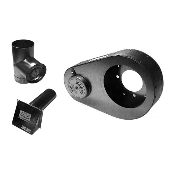
4" VRV
4" IAH HOOD
This product is designed for use on the following burners, for the purpose of routing
combustion air directly to the burner, with the added safety feature of the vacuum relief valve.
NOTE: For burner inputs up to 2.0 GPH at 100 PSI input pressure or equivalent.
"The Air Boot™ model CAS-2A is for use only on the designated burner(s) as described in
these instructions only when the specific burner includes this Air Boot™ when shipped from
the burner manufacturer or where the burner instructions specifically reference the models
CAS-2A Air Boot™ as an optional air intake system."
I
:
TEMS INCLUDED IN KIT
1 - Air Boot™
1 - 4" VRV
1 - 4" IAH Hood
1 - Burner Coupling Set
2 - Mounting Bolts
Model: CAS-2A
A
M
ERO
ODELS
F-AFC
HF-AFC
HF-US
SV SERIES
AIR BOOT™
I
NSTALLER SUPPLIED ITEMS
Duct Piping and Elbows
90° Elbows;
¼ " NPT Female x ¼" NPT
Male for routing oil line
:
Advertisement
Table of Contents

Subscribe to Our Youtube Channel
Related Manuals for Field Controls 46385600


Summary of Contents for Field Controls 46385600
- Page 1 COMBUSTION AIR SYSTEM Model: CAS-2A 4” VRV AIR BOOT™ 4” IAH HOOD This product is designed for use on the following burners, for the purpose of routing combustion air directly to the burner, with the added safety feature of the vacuum relief valve. NOTE: For burner inputs up to 2.0 GPH at 100 PSI input pressure or equivalent.
- Page 2 THE PURPOSE OF THE VRV The Vacuum Relief Valve is a safety device to guard against combustion problems associated with directly connecting oil burners to the outside. Typical problems can be caused by blockage of the intake termination, icing up of the duct work and effects of leeward side wind effects on a building. VRV O PERATION The VRV gate operates on changes in the vacuum pressure generated by the inlet to the oil burner.
- Page 3 2. Assemble VRV balance weight onto the gate. Screw the weight all the way in. Then attach lock nut and knurl nut. (See Figure 3) 3. Mount the VRV assembly onto the tee and fasten with a screw and nut in collar tabs. To ensure proper operation, check the gate for being level across the pivot points and plumb.
- Page 4 If draft levels are not obtainable or controllable, use standard industry methods to control the draft or call the Field Controls Tech Line at 1-800-742-8368 for more information. 3. Next, adjust the VRV gate by screwing the adjustment weight in until the VRV gate is just closed.
Need help?
Do you have a question about the 46385600 and is the answer not in the manual?
Questions and answers