Advertisement
TJERNLUND PRODUCTS, INC.
1601 Ninth Street • White Bear Lake, MN 55110-6794
PHONE (800) 255-4208 • (651) 426-2993 • FAX (651) 426-9547
Visit our web site • www.tjernlund.com
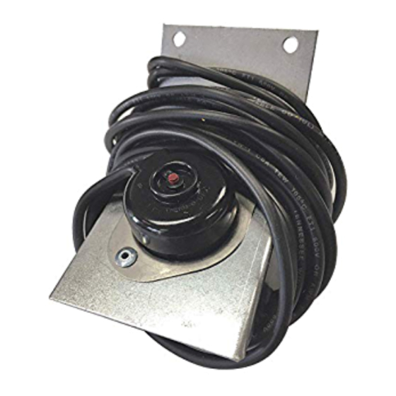
L-185 SAFETY INTERLOCK SYSTEM (P/N 950-2064)
(For Millivolt and 24 Volt Control Systems only)
This Safety Interlock System may be used on conventional chimney or Power Vented appliances
equipped with a draft hood, draft diverter or draft control.
To provide a means for appliance shut-down in the event of flue blockage or down drafts.
The Linear Limit Spillage Sensor circuit is "normally closed" and will not affect normal appliance opera-
tion. When concentrated spillage of combustion gases occurs from the draft hood, diverter or barometric
control, the Linear Limit Spillage Sensor circuit will open preventing burner operation.
QUANTITY
DESCRIPTION
(1)
Linear Limit Spillage Sensor with manual reset, 185
(1)
Linear Limit mounting packet
(1)
Wire routing packet
NOTE:
DO NOT CUT THE COPPER CAPILLARY SENSING TUBE!! TO DO SO
WOULD DESTROY IT AND DISABLE THE APPLIANCE.
1.
Shut off fuel supply to the appliance.
2.
Attach Linear Limit Spillage Sensor to draft hood (A1), diverter (A2) or barometric control (A3),
see respective diagram.
IMPORTANT:
Copper capillary sensing tube should not come in direct contact with metal sur-
faces. Linear Limit Spillage Sensor should be mounted so that capillary will sample
temperature of gases spilling from vent or chimney, not temperature of metal surface.
3a.
WATER HEATERS:
Millivolt water heaters require the Tjernlund Model JA-1 P/N 950-0470, Thermocouple Junction
Adapter (ordered separately). Connect ends of six foot cable to spade connections on
Thermocouple Adapter, (see Diagram B1).
3b.
FURNACES AND BOILERS:
Splice ends of six foot cable in a series circuit between the thermostat and gas valve or burner
control, (see Diagram B2).
4.
Using cable routing tabs from wire routing packet, attach Linear Limit control cable to appli-
ance maintaining a safe distance from hot surfaces, e.g. appliance vent pipe and hot water
pipes.
PURPOSE
OPERATION
PARTS LIST
o
set point and six foot cable
INSTALLATION
DIAGRAM A1
DIAGRAM A2
DIAGRAM A3
DIAGRAM B1
DIAGRAM B2
Advertisement
Table of Contents

Related Manuals for TJERNLUND 950-2064 L-185 SAFETY INTERLOCK KIT 8504020 REV 3 0996


Summary of Contents for TJERNLUND 950-2064 L-185 SAFETY INTERLOCK KIT 8504020 REV 3 0996
- Page 1 DIAGRAM B2 WATER HEATERS: Millivolt water heaters require the Tjernlund Model JA-1 P/N 950-0470, Thermocouple Junction Adapter (ordered separately). Connect ends of six foot cable to spade connections on Thermocouple Adapter, (see Diagram B1).
- Page 2 SERVICE PERSONNEL. Return all windows, doors and fans to their previous conditions of use. NOTE: For further assistance contact the Tjernlund Products, Inc. Customer Service Department at 1-800-255-4208. 7:30 AM-4:30 PM CST. REV. 3, 9/96 © 1996 TJERNLUND PRODUCTS, INC.
Need help?
Do you have a question about the 950-2064 L-185 SAFETY INTERLOCK KIT 8504020 REV 3 0996 and is the answer not in the manual?
Questions and answers