
Related Manuals for DH Instruments MPC1-D-1000


Summary of Contents for DH Instruments MPC1-D-1000
- Page 1 MPC1-D-1000/MPC1-D-3000 Manual Pressure Controller for Differential Pressure User’s Manual ©2000 DH Instruments, Inc.
- Page 2 MPC1-D User’s Manual Manual Conventions (Caution) is used in throughout the manual to identify user warnings and cautions. (NOTE) is used throughout the manual to identify operating and applications advice and additional explanations. High pressure liquids and gases are potentially hazardous. Energy stored in these liquids and gases can be released unexpectedly and with extreme force.
-
Page 3: Table Of Contents
MPC1-D User’s Manual TABLE OF CONTENTS ................i TABLES ....................ii FIGURES ....................ii 1. INTRODUCTION ..................1 PRODUCT OVERVIEW ..........................1 LOCATION OF THE COMPONENTS ......................1 SPECIFICATIONS .............................2 DIMENSIONAL SCHEMATICS........................3 2. INSTALLATION ..................5 UNPACKING AND INSPECTION ......................5 SITE REQUIREMENTS..........................5 INITIAL SETUP ............................5 3. - Page 4 MPC1-D User’s Manual Table 1. Variable Volume Specifications....................23 Table 2. DHI Authorized Service Providers................... 24 Figure 1. Front Panel ..........................1 Figure 2. Rear Panel..........................2 Figure 3. Side View with Dimensions ....................... 3 Figure 4. Top View with Dimensions ......................3 Figure 5.
-
Page 5: Introduction
Line Differential Pressure mode. A single channel model, MPC1, is available for applications other than differential pressures at elevated static pressures. MPC1-D-1000 is for pressures to 1 000 psi (7 MPa), MPC1-D-3000 is for pressures to 3 000 psi (21 MPa). -
Page 6: Specifications
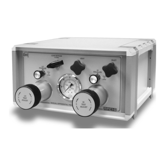
Vent Connection (1/8 in. NPT) Figure 2. Rear Panel 1.3 SPECIFICATIONS Pressure Range: MPC1-D-1000: Atmosphere to 1 000 psi (7 MPa) MPC1-D-3000: Atmosphere to 3 000 psi (21 MPa) Pressure Supply: Equal to or greater than the maximum pressure desired... -
Page 7: Dimensional Schematics
MPC1-D User’s Manual 1.4 DIMENSIONAL SCHEMATICS All dimensions are in millimeters. Figure 3. Side View with Dimensions Figure 4. Top View with Dimensions Page 3 ©2000 DH Instruments, Inc. - Page 8 MPC1-D User’s Manual Page 4 ©2000 DH Instruments, Inc...
-
Page 9: Installation
MPC1-D User’s Manual 2. I NSTALLATION 2.1 UNPACKING AND INSPECTION The MPC1-D is delivered with the inlet valve closed, exhaust valve open and the variable volume (VV) fully screwed in. Cap plugs cover all rear panel pressure connections. 2.2 SITE REQUIREMENTS •... - Page 10 MPC1-D User’s Manual Page 6 ©2000 DH Instruments, Inc...
-
Page 11: Operation
This instrument manually controls line pressure and differential pressures from atmosphere to 1 000 psi (7 MPa) (MPC1-D-1000) or atmosphere to 3 000 psi (21 MPa) (MPC1-D-3000) through the use of valves, two variable volume (VV) pumps, a bypass valve and a pressure gauge. -
Page 12: Variable Volume (Vv)
Under most operating conditions, the piston is placed in its mid-stroke position (about 16 rotations of the knob from either stop for MPC1-D-1000, 30 rotations for MPC1-D-3000). This will allow for equal movement, forward and backward, of the piston. -
Page 13: Pressure Gauge
MPC1-D User’s Manual 3.1.4 PRESSURE GAUGE There is a zero to 1 000 psi (7 MPa) or zero to 3 000 psi (21 MPa) dial gauge connected to the hi side test pressure circuit. The gauge has a dual function: •... -
Page 14: Increasing Line Pressure
MPC1-D User’s Manual 3.3.1 INCREASING LINE PRESSURE Open the HI/LO BYPASS valve. Open both variable volume equalization valves (pull knob outward). OPENING AN EQUALIZATION VALVE MAY RESULT IN A SUDDEN CHANGE IN THE TEST PRESSURE. Ensure conditions are such that this either does not happen or that its effects are inconsequential. -
Page 15: Setting Differential Pressures At Line Pressures
MPC1-D User’s Manual Adjust VV knob until desired line pressure is obtained (or until the piston floats when connected to a piston gauge). Maximum differential pressure across the VV piston is 150 psi (1 MPa). Pressures above 150 psi (1 MPa) will automatically open the equalization valve. To set a differential pressures after setting a line pressure, see Section 3.4. -
Page 16: Setting Single Channel Pressures
MPC1-D User’s Manual If the hi VV reaches end of stroke before the desired differential pressure is set, open the VV’s equalization valve and adjust it to an appropriate start position, then use the SUPPLY or VENT valve to admit or exhaust pressure. Be sure to open the hi VV equalization valve before operating the SUPPLY or VENT valve. -
Page 17: Decreasing Pressure
MPC1-D User’s Manual Open SUPPLY valve until the approximate desired pressure is reached. Care should be taken not to overrange the test. Close hi VV equalization valve (push knob inward). Adjust hi VV knob until desired pressure is obtained (or until the piston floats when connected to a piston gauge). - Page 18 MPC1-D User’s Manual Page 14 ©2000 DH Instruments, Inc.
-
Page 19: Maintenance And Adjustments
MPC1-D User’s Manual 4. M AINTENANCE DJUSTMENTS MPC1-D requires no routine maintenance or adjustments. Page 15 ©2000 DH Instruments, Inc... - Page 20 MPC1-D User’s Manual Page 16 ©2000 DH Instruments, Inc...
-
Page 21: Troubleshooting
MPC1-D User’s Manual 5. T ROUBLESHOOTING 5.1 GENERAL INFORMATION The MPC1-D consists of three valves, two variable volumes (VV), a pressure gauge and various tubing and fittings. Several predictable failures can occur while using the instrument and are addressed in this section. It is recommended that whomever performs the following troubleshooting procedures become familiar with the system schematic (see Section 6.1) including the VV description (see Section 6.2). -
Page 22: Test Pressure Will Not Change
MPC1-D User’s Manual 5.3 TEST PRESSURE WILL NOT CHANGE There are five components involved in changing the pressure: • SUPPLY valve. • Variable Volumes (2). • VENT valve. • HI/LO BYPASS valve. The MPC1 uses very small inside diameter control tubes. The purpose of the filters is to protect these tubes and the valves from contamination. -
Page 23: Vent Valve
MPC1-D User’s Manual 5.3.3 VENT VALVE Three problems can cause the failure of the VENT valve to change pressures: • An incorrectly positioned outlet selection valve. • A closed equalization valve. • A plugged filter. Ensure the outlet selection valve is in the proper position for the work being done (either VENT or VACUUM). - Page 24 MPC1-D User’s Manual Page 20 ©2000 DH Instruments, Inc...
-
Page 25: Annexes
MPC1-D User’s Manual 6. A NNEXES 6.1 PNEUMATIC SCHEMATIC Variable volume (lo side) Vent connection (1/8 in. NPT) Variable volume equalization valve (lo side) 10. Gas supply connection (1/8 in. NPT) Check valve 11. Inlet valve Filter 12. Variable volume (hi side) Lo ref connection (1/8 in. -
Page 26: Variable Volume Information
MPC1-D User’s Manual 6.2 VARIABLE VOLUME INFORMATION VENT VALVE INLET VALVE EQUALIZATION VALVE CLOSED SYSTEM IN TEST MODE (EQUALIZATION VALVE CLOSED) TEST SIDE PISTON VENT INLET EQUALIZATION VALVE OPEN SYSTEM IN PRESSURE EQUALIZATION OR VENT MODE (EQUALIZATION VALVE OPEN) TEST SIDE PISTON Figure 6. -
Page 27: Variable Volume Specifications
MPC1-D User’s Manual 6.2.1 VARIABLE VOLUME SPECIFICATIONS Table 1. Variable Volume Specifications MPC1-1000 MPC1-3000 Range Vacuum to 1 000 psi Vacuum to 3 000 psi Proof 3 000 psi 6 000 psi Burst 6 000 psi min 12 000 psi min Approx. -
Page 28: Table 2. Dhi Authorized Service Providers
MPC1-D User’s Manual Table 2. DHI Authorized Service Providers DH INSTRUMENTS, INC. www.dhinstruments.com AUTHORIZED SERVICE PROVIDERS TELEPHONE COMPANY ADDRESS & FAX EMAIL DH Instruments, Inc. 4765 East Beautiful Lane Tel 602.431.9100 cal.repair@dhinstruments.com Phoenix, AZ 85044-5318 Fax 602.431.9559 2-9-1 Sengen, Tsukuba-Shi Tel 0298-55-8778 tohte@ohtegiken.co.jp Nippon CalService, Inc.
Need help?
Do you have a question about the MPC1-D-1000 and is the answer not in the manual?
Questions and answers