
Related Manuals for DH Instruments OPG1


Summary of Contents for DH Instruments OPG1
- Page 1 OPG1™ Hydraulic Pressure Generator/Controller Operation and Maintenance Manual © 1998-2007 DH Instruments, a Fluke Company...
- Page 2 In case of conflict between the English version and other language versions, the English version predominates. DH Instruments, DH, DHI, OPG1, RPM3, PG7000 and CalTool are trademarks, registered and otherwise, of DH Instruments, a Fluke Company. Swagelok is a registered trademark of the Swagelok Company.
-
Page 3: Table Of Contents
CONNECTING A DEVICE UNDER TEST (DUT)..................23 3.2.5 PURGING AIR FROM THE DUT/SYSTEM UNDER TEST................24 3.2.6 MEASUREMENT REFERENCE LEVEL WHEN VENTED ................24 TYPICAL OPERATING SEQUENCE FOR A COMPLETE CALIBRATION OR TEST ......25 Page I © 1998-2007 DH Instruments, a Fluke Company... - Page 4 A P P E N D I X ............... 3 3 OPG1 TERMS, LABELS, AND SYMBOLS (GLOSSARY) ..............33 WARRANTY STATEMENT ........................34...
- Page 5 Figure 2. Front and Side Views with Dimensions ..................3 Figure 3. System Schematic ........................4 Figure 4. Configuring Pneumatic Power Connections ................11 Figure 5. Connecting OPG1 to PG7302 or RPM3 ..................12 Figure 6. Hydropneumatic Pump ......................16 Figure 7. System Schematic ........................20 Figure 8.
-
Page 6: A B O U T T H I S M A N U Al
FOR THOSE OF YOU WHO “DON’T READ MANUALS”, GO DIRECTLY TO SECTION 2.3 TO SET UP YOUR OPG1. THEN GO TO SECTION 4.3. THIS WILL GET YOU RUNNING QUICKLY WITH MINIMAL RISK OF CAUSING DAMAGE TO YOURSELF OR YOUR OPG1. THEN… WHEN YOU HAVE QUESTIONS... -
Page 7: Introduction
It is capable of both generating and precisely adjusting pressure from atmosphere to 200 MPa (30 000 psi). OPG1 combines the versatility, speed and reliability of direct operator control with the convenience and effort-free operation of automation. It is the standard pressure generating and control component in a DHI PG7302 piston gauge system or combined with an RPM3 digital pressure monitor to configure a transfer standard based calibration system. -
Page 8: Instrument Layout
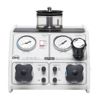
Pump Drive Air/Inlet Oil Pressure Gauge Pump Drive Air Set Regulator Test Inlet Valve Knob PDVV Increase Fast and Slow Buttons PDVV Decrease Fast and Slow Buttons Test Outlet Valve Knob Figure 1. Front Panel © 1998-2007 DH Instruments, a Fluke Company Page 2... -
Page 9: Overall Dimensions
1. INTRODUCTION 1.3.2 OVERALL DIMENSIONS Figure 2. Front and Side Views with Dimensions Page 3 © 1998-2007 DH Instruments, a Fluke Company... -
Page 10: System Schematic
PDVV DRIVE to PDVV Independent Connection) 10. Pneumatically Drive Variable Volume 20. PDVV DRIVE to PDVV Independent Connection (PDVV) (as delivered) 11. Fast and Slow PDVV Decrease Valves 21. Oil Filters Figure 3. System Schematic © 1998-2007 DH Instruments, a Fluke Company Page 4... -
Page 11: Installation
UNPACKING AND INSPECTION 2.1.1 REMOVING FROM PACKAGING OPG1 is delivered, along with its standard accessories in a corrugated container with corrugated and polyurethane inserts to hold it in place. Remove the OPG1 and its accessories from the shipping container and remove each element from its protective plastic bag. -
Page 12: Site Requirements
OPG1 hydraulic fittings are all DH500 (equivalent to AE F250C, HIP HF4, etc.). The female DH500 fittings are delivered with glands, nuts and plugs installed. Collars are included in the accessory kit. If you do not plan to use OPG1’s top TEST port, consider where a device or system under test (DUT) will be connected. -
Page 13: Initial Setup
2. INSTALLATION INITIAL SETUP 2.3.1 PREPARING FOR OPERATION Before setting up the OPG1, see Section 2.2 for general information on site requirements. To prepare an OPG1 for check out and operation: • Set up the OPG1 (see Section 2.3.1.1). •... -
Page 14: Table 2. Pneumatic Power (Drive Air) Requirements
The drive air pressure needed for the PDVV, if accidentally supplied to the hydropneumatic pump, could accidentally cause an overpressure situation that would be hazardous to the system connected to the OPG1. OPG1 is delivered set up for two independent pneumatic power connections. - Page 15 Once the OPG1 is properly configured for a single pneumatic power connection, connect the pneumatic pressure source to the 1/4 in. NPT F connection labeled DRIVE on the right side of the OPG1 housing. Use Teflon™ tape or another thread sealant to minimize leakage.
- Page 16 Close the OPG1 tank cover fully and plug all hydraulic TEST ports. Place the OPG1 back down on the bench, so that the front panel is straight up and the open bottom is towards you. Make sure that there is enough oil in the tank so that the pump draw port remains covered.
-
Page 17: Make Hydraulic Pressure Interconnections
These setups assume that the TEST port at the top of the OPG1 oil tank or an open leg of the tee will be used to connect the DUT. To adapt to the top test port connection, install one of the DH500 F x 1/8 in. NPT M or DH500 F x 1/4 in. -
Page 18: Figure 5. Connecting Opg1 To Pg7302 Or Rpm3
When planning a DUT or other fitting make and break point external to OPG1, consider that if the point is lower than the OPG1 oil tank, oil will run out of the tank through the open point when OPG1’s OUTLET valve is open. -
Page 19: Power Up And Verification
OPG1 hydraulic output pressure is directly proportional to pump DRIVE pressure. When the OPG1 INLET valve is opened, the full pump pressure may be applied to the test system very rapidly. ALWAYS adjust the pump pneumatic drive pressure low enough so that the maximum pump output does not exceed the maximum pressure rating of the devices to which OPG1 is connected. -
Page 20: Step Two: Generating A Pressure
Proceed as follows (numerical references refer to Section 3.1, Figure 7): Verify that there is oil in the tank. Connect a high pressure indicating device to one of the OPG1 TEST ports (4, 6, 7). Plug all other TEST ports (4, 6, 7). -
Page 21: Priming The Hydropneumatic Pump By Syringe Injection
Numerical references in this section refer to Section 4.2, Figure 11. To prime the pump with the syringe proceed as follows: Back off the OPG1 DRIVE SET regulator to zero by turning it fully CCW. Open INLET valve and OUTLET valve. -
Page 22: Precautions To Take Before Generating Pressure/Safety Considerations
PRESSURE/SAFETY CONSIDERATIONS Before using the OPG1 to generate and adjust pressure, consider the following: • Check that all connections, vessels and DUTs connected to OPG1 are rated for the pressure to be generated and that all fittings are properly tightened. •... -
Page 23: Short Term Shut-Down
(see Section 3.2.5). • If there is an open point in the system to which OPG1 is connected that is lower than the OPG1 tank, oil will run out of the OPG1 tank through this point when the OUTLET valve is open. - Page 24 OPG1™ OPERATION AND MAINTENANCE MANUAL © 1998-2007 DH Instruments, a Fluke Company Page 18...
-
Page 25: G E N E R A L O P E R A T I O
200 MPa (30 000 psi). The pump draws oil from the oil tank on top of OPG1. The DRIVE SET regulator (1) is used to set the pneumatic drive pressure and thus the oil output pressure. -
Page 26: Figure 7. System Schematic
10. Pneumatically Drive Variable Volume 20. PDVV DRIVE to PDVV Independent Connection (PDVV) (as delivered) 11. Fast and Slow PDVV Decrease Valves 21. Oil Filters Fast and Slow PDVV Increase Valves Figure 7. System Schematic © 1998-2007 DH Instruments, a Fluke Company Page 20... -
Page 27: Operational Functions
3. GENERAL OPERATION OPERATIONAL FUNCTIONS All OPG1 operational functions are accessed from the instrument front panel. Sections 3.2.1 to 3.2.6 detail the various functions. PDVV Drive Air/Test Oil Pressure Gauge PDVV Piston Position Indicator Pump Drive Air/Inlet Oil Pressure Gauge... -
Page 28: Rough Pressure Generation/Control, Inlet And Outlet Valve Operation
When the INLET valve is opened, high pressure can be generated very rapidly in the system connected to OPG1. Use caution in opening the INLET valve and always check the PUMP DRIVE gauge before doing so (see Sections 2.4.1 and 3.2.1). -
Page 29: Connecting A Device Under Test (Dut)
OPG1 accessories. Install the tube into the adaptor. OPG1 covers a very wide range of pressures all the way up to 200 MPa (30 000 psi). It is the user’s responsibility to assure that fittings and devices connected to OPG1 are rated for the pressures at which they will be used. -
Page 30: Purging Air From The Dut/System Under Test
The system and/or DUTs that are connected to OPG1 can be filled with oil prior to connecting them or they can be purged using OPG1. To purge air using OPG1, open the system or DUT at the highest point possible. Close the OPG1 OUTLET valve. Then carefully open the INLET valve causing oil to be drawn from the tank and pumped into the system. -
Page 31: Typical Operating Sequence For A Complete Calibration Or Test
The typical operational sequence is as follows (numerical references refer to Section 3.2, Figure 8): Connect the DUT to the OPG1 TEST port or to a test port on the external system to which OPG1 is connected. - Page 32 OPG1™ OPERATION AND MAINTENANCE MANUAL © 1998-2007 DH Instruments, a Fluke Company Page 26...
-
Page 33: M A I N T E N A N C E A D J U S T M E N T S A N D C A L I B R A T I O
FILLING THE TANK The oil level in the OPG1 tank should be maintained at all times. Opening the INLET valve and operating the hydropneumatic pump when the tank is empty will cause the pump to draw air and lose its prime. -
Page 34: Replacing Oil And Purging Contaminated Oil
OPG1 will be contaminated. Observe the oil in the OPG1 tank. If its color is significantly different from the color of clean oil or if any particulate contamination can be observed, replace the oil in the oil tank and purge the OPG1 oil system. -
Page 35: Figure 12. Drive Air Filters
4. MAINTENANCE ADJUSTMENTS AND CALIBRATION To remove and reinstall the drive air filters, proceed as follows: Close the OPG1 tank cover fully and plug all hydraulic ports. Ensure that tank is filled to just under oil return tube. Place the OPG1 back down on the bench, so that the front panel is up with the open bottom towards you. - Page 36 OPG1™ OPERATION AND MAINTENANCE MANUAL © 1998-2007 DH Instruments, a Fluke Company Page 30...
-
Page 37: T R O U B L E S H O O T I N
Before assuming that unexpected behavior is caused by a system defect or breakdown, the operator should use this manual and other training facilities to become thoroughly familiar with OPG1 operation. This troubleshooting guide is intended as an aid in identifying the cause of unexpected OPG1 behavior and determining whether the behavior is due to normal operation or an internal or external problem. - Page 38 OPG1 tank and the OUTLET valve closed when any point at a OUTLET valve is open so oil is lower height than the OPG1 tank is open. running out from the tank. Pressure is not returning to zero...
-
Page 39: A P P E N D I
Analog gauge that indicates the pump drive air pressure and the approximate PUMP DRIVE Gauge corresponding pump oil output pressure. The oil pressure in the OPG1 PDVV, at its TEST connections and in the system to which Test Pressure the OPG1 is connected. -
Page 40: Warranty Statement
OPG1™ OPERATION AND MAINTENANCE MANUAL WARRANTY STATEMENT Except to the extent limited or otherwise provided herein, DH Instruments, a Fluke Company (DHI) warrants for one year from purchase, each new product sold by it or one of its authorized distributors, only against defects in workmanship and/or materials under normal service and use.
Need help?
Do you have a question about the OPG1 and is the answer not in the manual?
Questions and answers