
Related Manuals for DH Instruments OPG1-30000-AF


Summary of Contents for DH Instruments OPG1-30000-AF
- Page 1 T.O. 33A6-4-30-1 OPG1-30000-AF™ Oil Pressure Generator/Controller Operation and Maintenance Manual NSN 6685-01-470-8667 (1 of 2) 1 August 2000 ©2000 DH Instruments, Inc.
- Page 2 In case of conflict between the English version and other language versions, the English version predominates. DH Instruments, DH, DHI, OPG1, OPG1-30000-AF, RPM3, RPM3/HPMS, PG7000 and CalTool are trademarks, registered and otherwise, of DH Instruments, Inc. Swagelok is a registered trademark of the Swagelok Company.
-
Page 3: Table Of Contents
2 . 2 SITE REQUIREMENTS..........................8 2 . 3 INITIAL SETUP............................9 2.3.1 PREPARING FOR OPERATION ........................9 2.3.1.1 SET UP THE OPG1-30000-AF ......................9 2.3.1.2 CONNECT PNEUMATIC POWER (DRIVE AIR) ................9 2.3.1.3 MAKE HYDRAULIC PRESSURE INTERCONNECTIONS ..............11 2.3.1.4 CONNECTING TO A DEVICE UNDER TEST .................12 2 . - Page 4 OPG1™ Operation and Maintenance Manual 4 . 2 FILLING THE TANK ..........................28 4 . 3 REPLACING OIL AND PURGING CONTAMINATED OIL ..............29 4 . 4 PRIMING THE HYDROPNEUMATIC PUMP ................... 30 4.4.1 PRIMING THE HYDROPNEUMATIC PUMP BY SYRINGE INJECTION ............30 4.4.2 INTERNAL PURGE OF HYDROPNEUMATIC PUMP ..................31 4 .
- Page 5 Front Panel ..........................3 Figure 2. Front and Side Views with Dimensions ..................4 Figure 3. System Schematic........................5 Figure 4. Connecting OPG1-30000-AF to an RPM3/HPMS..............11 Figure 5. System Schematic........................20 Figure 6. Front Panel ..........................21 Figure 7.
-
Page 6: About This Manual
FOR THOSE OF YOU WHO “DON’T READ MANUALS”, GO DIRECTLY TO SECTION 2.3 TO SET UP YOUR OPG1-30000-AF. READ SECTION 2.4.4 AND GO TO SECTION 3.3. THIS WILL GET YOU UP AND RUNNING QUICKLY WITH MINIMAL RISK OF CAUSING DAMAGE TO YOURSELF OR YOUR OPG1. -
Page 7: Introduction
It is capable of both generating and precisely adjusting pressure from atmosphere to 200 MPa (30 000 psi). OPG1-30000-AF combines the versatility, speed and reliability of direct operator control with the convenience and effort-free operation of automation. It is the standard pressure generating and control component in an HGC-30000-AF Hydraulic Gauge Calibration system as well as in a PG7302 piston gauge system. -
Page 8: Specifications
OPG1™ Operation and Maintenance Manual 1.2 SPECIFICATIONS Electrical Power Requirements None Pneumatic Power Requirements Clean, dry, compressed air @ 50 slm (1.8 scfm) flow. Maximum pressure needed depends on maximum oil pressure desired: - 70 MPa (10 000 psi): 550 kPa (80 psi) - 140 MPa (20 000 psi): 700 kPa (100 psi) - 200 MPa (30 000 psi): 850 kPa (120 psi) Operating Temperature Range... -
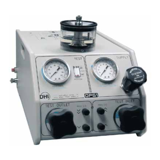
Page 9: Instrument Layout
OPG1™ Operation and Maintenance Manual 1.3 INSTRUMENT LAYOUT 1.3.1 FRONT PANEL The front panel provides all of the controls and indications needed to set and adjust pressure. PDVV Drive Air/Test Oil Pressure Gauge PDVV Piston Position Indicator Pump Drive Air/Inlet Oil Pressure Gauge Pump Drive Air Set Regulator Test Inlet Valve Knob PDVV Increase Fast and Slow Buttons... -
Page 10: Overall Dimensions
OPG1™ Operation and Maintenance Manual 1.3.2 OVERALL DIMENSIONS Figure 2. Front and Side Views with Dimensions Page 4 ©2000 DH Instruments, Inc. -
Page 11: System Schematic
OPG1™ Operation and Maintenance Manual 1.3.3 SYSTEM SCHEMATIC Pump Drive Air Set Regulator Fast and Slow PDVV Decrease Valves Hydropneumatic Pump Fast and Slow PDVV Increase Valves Tank PDVV DRIVE Air Connection Top TEST Connection Common DRIVE Air Connection Oil Return Overflow Tube DRIVE Air Filters Right Side TEST Connection PUMP DRIVE Pressure Gauge... - Page 12 OPG1™ Operation and Maintenance Manual Page 6 ©2000 DH Instruments, Inc.
-
Page 13: Installation
2.1 UNPACKING AND INSPECTION 2.1.1 REMOVING FROM PACKAGING OPG1-30000-AF is delivered, along with its standard accessories in a corrugated container with corrugated and polyurethane inserts to hold it in place. Remove the OPG1 and its accessories from the shipping container and remove each element from its protective plastic bag. -
Page 14: Site Requirements
RPM3/HPMS-A30000/A6000-AF that Operation Maintenance Manual. When selecting and preparing a site to set up the OPG1-30000-AF and HGC-30000-AF system, the following should be considered: • Bench Stability: The OPG1 weighs about 27 kg (60 lb). The RPM3/HPMS-A30000/A6000-AF weighs about 10 kg (22 lbs). Consider the combined weight and that of other components, including possible items to be tested, when selecting a bench. -
Page 15: Initial Setup
Connect pneumatic power (see Section 2.3.1.2). Make the system hydraulic pressure interconnections (see Section 2.3.1.3). 2.3.1.1 SET UP THE OPG1-30000-AF To set up the OPG1, proceed as follows: Place the OPG1 platform on the site table in the proper orientation with the front panel controls conveniently accessible. -
Page 16: Table 2. Pneumatic Power (Drive Air) Requirements
OPG1™ Operation and Maintenance Manual Make the two drive air connections as follows (but do not supply the air before reading Section 2.4.3.2): “DRIVE” connection (right side, rear): Connect a regulated air supply meeting the requirements of Table 2 to the 1/4 in. NPT F “DRIVE” connection. This is usually a shop air supply. -
Page 17: Make Hydraulic Pressure Interconnections
MAKE HYDRAULIC PRESSURE INTERCONNECTIONS CONNECTING TO THE RPM3/HPMS-A30000/A6000-AF OPG1-30000-AF is delivered with a fittings accessory kit (see Section 2.1.2, Table 1). This kit includes the high pressure hardware necessary to connect OPG1-30000-AF to the RPM3/HPMS-A30000/A6000-AF. See Figure 4 for the recommended layout and to identify the parts used from the interconnection kit. -
Page 18: Connecting To A Device Under Test
1/4 in. (6.35 mm) coned and left hand threaded tube. DH500 is equivalent to AE F250C, HIP HF4, etc. The OPG1-30000-AF fittings accessory kit includes adaptors to convert the DH500 F TEST connection to other commonly used fittings. The adaptors are made by combining a DH500 F adaptor with a 2.75 in. -
Page 19: Power Up And Verification
OPG1™ Operation and Maintenance Manual The DH500 test connection can be converted to 1/8 in. NPT M or 1/4 in. NPT M using the 2.75 in. (7 mm) tube and DH500 F x 1/8 in. NPT M or DH500 F x 1/4 in. NPT M adaptor supplied in the OPG1 accessories. -
Page 20: Adjust Hydropneumatic Pump Drive Air Pressure
OPG1™ Operation and Maintenance Manual 2.4.2 ADJUST HYDROPNEUMATIC PUMP DRIVE AIR PRESSURE This section assumes that the OPG1-30000-AF system has already been set up, including pressure interconnection (see Section 2.3). OGP1 hydraulic output pressure is directly proportional to pump DRIVE pressure. When the OPG1 INLET valve is opened, the full pump pressure may be applied to the test system very rapidly. -
Page 21: Step Two: Generating A Pressure
OPG1™ Operation and Maintenance Manual Observe tank oil return overflow tube (5). Continue allowing pump to cycle until bubble free oil flows regularly from the tube. If no oil appears, or bubbles continue to appear, a cavitated pump priming procedure must be used (see Section 4.4). -
Page 22: Precautions To Take Before Generating Pressure/Safety Considerations
OPG1™ Operation and Maintenance Manual The pump should begin to cycle and the pressure indicated on the high pressure device should increase. If the pump does not cycle, the drive pressure is set too low or the pump is not operating correctly. If the pump cycles but the pressure does not increase: •... - Page 23 OPG1™ Operation and Maintenance Manual • Opening INLET valve opens test system output hydropneumatic pump. As long as the INLET valve is open, the pump will cycle until it stalls. To avoid accidental overpressure of the items to which OPG1 is connected, always adjust the DRIVE SET regulator so that the hydropneumatic pump output will be lower than the maximum desired pressure BEFORE opening the INLET valve (see Sections 2.4.2 and 3.2.1).
-
Page 24: Short Term Shut-Down
Disconnect all hydraulic pressure connections and plug the connections using DH500 plugs held by gland nuts (DH500 plugs were delivered with OPG1-30000-AF). There are three hydraulic connections: one on either side labeled TEST and one on top at the center of the tank cover. -
Page 25: General Operation
3.1 OPERATING PRINCIPLE Numerical references in this section refer to Section 3.1, Figure 5. OPG1-30000-AF is a self-contained system designed to generate and adjust pressure from atmosphere (zero gauge) to 200 MPa (30 000 psi) in and HGC-30000-AF Hydraulic Gauge Calibrator System. -
Page 26: Figure 5. System Schematic
OPG1™ Operation and Maintenance Manual Pump Drive Air Set Regulator Fast and Slow PDVV Decrease Valves Hydropneumatic Pump Fast and Slow PDVV Increase Valves Tank PDVV DRIVE Air Connection Top TEST Connection Common DRIVE Air Connection Oil Return Overflow Tube DRIVE Air Filters Right Side TEST Connection PUMP DRIVE Pressure Gauge... -
Page 27: Operational Functions
OPG1™ Operation and Maintenance Manual 3.2 OPERATIONAL FUNCTIONS All OPG1 operational functions are accessed from the instrument front panel. Sections 3.2.1 to 3.2.6 detail the various functions. PDVV Drive Air/Test Oil Pressure Gauge PDVV Piston Position Indicator Pump Drive Air/Inlet Oil Pressure Gauge Pump Drive Air Set Regulator Test Inlet Valve Knob PDVV Increase Fast and Slow Buttons... -
Page 28: Rough Pressure Generation/Control, Inlet And Outlet Valve Operation
OPG1™ Operation and Maintenance Manual With the INLET valve (5) closed, use the DRIVE SET regulator (4) and the PUMP DRIVE gauge (3) indication to set the desired maximum pump output pressure. This is generally done at the beginning of a test or calibration based on the maximum pressure of the calibration. -
Page 29: Fine Pressure Adjustment, Pdvv (+) And (-) Valve Operation
OPG1™ Operation and Maintenance Manual 3.2.3 FINE PRESSURE ADJUSTMENT, PDVV (+) AND (-) VALVE OPERATION Numerical references in this section refer to Section 3.2, Figure 6 except where specified otherwise. The PDVV (+) valves (6) and PDVV (-) valves (7) are push button, poppet valves that control the supply and exhaust of drive air pressure to the PDVV actuator (see Section 3.1). -
Page 30: Connecting A Device Under Test (Dut)
OPG1™ Operation and Maintenance Manual For the PDVV (+) valves (6) and PDVV (-) valves (7) to have an effect, the PDVV plunger must have stroke available. If the PDVV is at its end of stroke (Figure 7, Ref 1 or 3), the plunger cannot move to change pressure. -
Page 31: Measurement Reference Level When Vented
OPG1™ Operation and Maintenance Manual 3.2.6 MEASUREMENT REFERENCE LEVEL WHEN VENTED Generally, the test or calibration system is opened to atmosphere (zero gauge pressure) by opening the OPG1 OUTLET valve. The fluid head reference level when the OUTLET valve is open is the top of the tank return overflow tube. -
Page 32: Typical Operating Sequence For A Complete Calibration Or Test
OPG1™ Operation and Maintenance Manual 3.3 TYPICAL OPERATING SEQUENCE FOR A COMPLETE CALIBRATION OR TEST OPG1-A30000-AF is most often used to generate and adjust pressures to a reference measuring device and a DUT when performing a test or calibration. In an HGC-30000-AF the reference measuring device is an RPM3/HPMS-A30000/A6000-AF. -
Page 33: Maintenance Adjustments And Calibration
OPG1™ Operation and Maintenance Manual 4. M AINTENANCE DJUSTMENTS ALIBRATION 4.1 OVERVIEW OPG1 was designed for maintenance free operation. The hydropneumatic pump and PDVV are permanently lubricated. No maintenance is required other than: • Maintain oil level in tank: Replace lost oil to never allow the tank to empty which would cause the pump to run without oil (see Section 4.2). -
Page 34: Filling The Tank
OPG1™ Operation and Maintenance Manual OPG1 is a sophisticated pressure generation and adjusting instrument with advanced features and functions. Before assuming that unexpected behavior is caused by a system defect or breakdown, use this manual and other training facilities to become thoroughly familiar with OPG1 operation. -
Page 35: Replacing Oil And Purging Contaminated Oil
OPG1™ Operation and Maintenance Manual 4.3 REPLACING OIL AND PURGING CONTAMINATED OIL If OPG1 is used to generate and adjust pressure into test systems and DUTs that are not clean, the oil returned to OPG1 will become contaminated. Observe the oil in the OPG1 tank. If its color is significantly different from the color of clean oil or if any particulate contamination can be observed, replace the oil in the oil tank and purge the OPG1 oil system. -
Page 36: Priming The Hydropneumatic Pump
OPG1™ Operation and Maintenance Manual 4.4 PRIMING THE HYDROPNEUMATIC PUMP If hydropneumatic pump is filled with air (cavitated), if will pump continuously when drive air is applied without drawing oil from the tank or generating oil pressure. If you believe the pump may be cavitated, first attempt to purge it following the procedure described in Section 2.4.3.1. -
Page 37: Internal Purge Of Hydropneumatic Pump
OPG1™ Operation and Maintenance Manual 4.4.2 INTERNAL PURGE OF HYDROPNEUMATIC PUMP The hydropneumatic pump internal purge procedure is only required if the regular purge procedure fails (see Section 2.4.3.1) and a syringe is not available to perform the injection priming procedure (see Section 4.4.1). To purge the hydropneumatic pump internally, proceed as follows (see Figure 10): 1. -
Page 38: Cleaning/Replacing Drive Air Filter Elements
OPG1™ Operation and Maintenance Manual 4.5 CLEANING/REPLACING DRIVE AIR FILTER ELEMENTS There are filters on the OPG1 drive air inlet ports, one on the PDVV DRIVE port and the other on the DRIVE port. If the drive air supplied is excessively dirty, the filters may become contaminated and restrict air flow to the PDVV and/or hydropneumatic pump (see Section 3.1, Figure 6). -
Page 39: Troubleshooting
OPG1™ Operation and Maintenance Manual 5. T ROUBLESHOOTING PG1 is a sophisticated pressuring generating and adjusting instrument with advanced features and functions. Before assuming that unexpected behavior is caused by a system defect or breakdown, the operator should use this manual and other training facilities to become thoroughly familiar with OPG1 operation. - Page 40 OPG1™ Operation and Maintenance Manual Table 3. OPG1 Troubleshooting Checklist (Continued) SYMPTOM PROBABLE CAUSE SOLUTION PDVV will not increase pressure. PDVV is at maximum end of Verify PDVV piston position and stroke position, PDVV supply readjust if necessary. Use INLET pressure is not high enough, or valve to increase pressure.
-
Page 41: Appendix
OPG1™ Operation and Maintenance Manual 6. A PPENDIX 6.1 WARRANTY STATEMENT Except to the extent limited or otherwise provided herein, DH Instruments, Inc. warrants for one year from purchase (five years for OPG1-A30000-AF units purchased under AFMETCAL Contract F33660-99-C7003, as labeled on the instrument rear panel), each new product sold by it or one of its authorized distributors, only against defects in workmanship and/or materials under normal service and use. -
Page 42: Table 4. Dhi Authorized Service Providers
OPG1™ Operation and Maintenance Manual Table 4. DHI Authorized Service Providers DH INSTRUMENTS, INC. AUTHORIZED SERVICE PROVIDERS 2000 JAN NORMAL TELEPHONE, FAX SUPPORT COMPANY ADDRESS EMAIL REGION DH Instruments, Inc. 4765 East Beautiful Lane Tel 602.431.9100 Worldwide Phoenix AZ 85044-5318 Fax 602.431.9559 jbaines@dhinstruments.com Minerva I.P.&M. -
Page 43: Glossary
OPG1™ Operation and Maintenance Manual and slow Fast , PDVV (-) valves. Used to decrease pressure and for fine pressure adjustment. Fast and slow , PDVV (+) valves. Used to increase pressure and for fine pressure adjustment. Clockwise Counter-clockwise Collar The DH500 fitting element that is threaded onto the tube and provides a surface for the gland to push against. - Page 44 OPG1™ Operation and Maintenance Manual PDVV (+) Valves Momentary, push button actuated, poppet valves that admit air drive pressure to the PDVV actuator causing the PDVV plunger to move forward, compressing oil and increasing the test pressure. Used to increase pressure and for fine pressure adjustment. PDVV (-) Valves Momentary, push button actuated, poppet valves that release air drive pressure from the PDVV actuator causing the PDVV plunger to move...
Need help?
Do you have a question about the OPG1-30000-AF and is the answer not in the manual?
Questions and answers