
Related Manuals for DH Instruments PPCH - V1.01


Summary of Contents for DH Instruments PPCH - V1.01
- Page 1 PPCH™ Hydraulic Pressure Controller/Calibrator Ver. 1.01f and higher Operation and Maintenance Manual © 2009 DH Instruments, a Fluke Company...
- Page 2 This instrument is not to be operated in any other manner than that specified by the manufacturer. © 2009 DH Instruments, a Fluke Company All rights reserved. Information in this document is subject to change without notice. No part of this document may be reproduced or transmitted in any form or by any means, electronic or mechanical, for any purpose, without the express written permission of DH Instruments, a Fluke Company 4765 East Beautiful Lane, Phoenix AZ 85044-5318, USA.
-
Page 3: Table Of Contents
CHECKING GAUGE MODE PRESSURE MEASUREMENT ..............19 2.4.4 PRIME AND PURGE TEST SYSTEM......................19 2.4.5 LEAK CHECK ..............................19 2.4.6 CHECK PRESSURE CONTROL OPERATION ...................19 STORAGE AND SHIPPING ........................20 2.5.1 SHORT TERM STORAGE ...........................20 2.5.2 LONG TERM STORAGE ..........................20 Page I © 2009 DH Instruments, a Fluke Company... - Page 4 <1AUTOZ> ..............................74 3.5.1.1 EDIT AUTOZ ............................77 3.5.1.2 RUN AUTOZ.............................78 3.5.2 <2REMOTE> ..............................79 3.5.2.1 <1COM1, 2COM2>...........................80 3.5.2.2 <3IEEE-488> ............................80 3.5.2.3 <4FORMAT> ............................80 3.5.2.4 <5RS232 SELF-TEST> ..........................81 3.5.3 <3HEAD> ..............................81 3.5.4 <4RESET> ..............................82 © 2009 DH Instruments, a Fluke Company Page II...
-
Page 5: Table Of Contents
ADJUSTMENT OF ON-BOARD BAROMETER...................144 ADJUSTMENT OF UTILITY SENSOR ....................144 FILLING AND DRAINING THE FLUID RESERVOIR ................145 5.6.1 INTERNAL RESERVOIR ...........................145 5.6.1.1 FILLING THE INTERNAL RESERVOIR....................145 5.6.1.2 DRAINING THE INTERNAL RESERVOIR.....................146 5.6.2 EXTERNAL RESERVOIR ..........................146 Page III © 2009 DH Instruments, a Fluke Company... - Page 6 G L O S S A R Y ..............1 8 1 © 2009 DH Instruments, a Fluke Company...
-
Page 7: Tables
Table 28. External drivers current output....................177 Table 29. External drivers pin outs ......................177 Table 30. Pressure unit of measure conversion coefficients ..............178 Table 31. DHI Authorized Service Providers ................... 179 Page V © 2009 DH Instruments, a Fluke Company... - Page 8 Figure 21. Electronic module, internal view ..................... 167 Figure 22. Mechanical module, internal view................... 169 Figure 23. Drivers connector schematic ....................177 Figure 24. Remote [ENT/SET P] connector schematic ................178 © 2009 DH Instruments, a Fluke Company Page VI...
-
Page 9: A B O U T T H I S M A N U Al
(NOTE) is used throughout the manual to identify operating and applications advice and additional explanations. [ ] indicates direct function keys (e.g., [RANGE]). < > indicates PPCH screen displays (e.g., <1yes>). Page VII © 2009 DH Instruments, a Fluke Company... - Page 10 PPCH™ OPERATION AND MAINTENANCE MANUAL © 2009 DH Instruments, a Fluke Company Page VIII...
-
Page 11: I N T R O D U C T I On
PPCH models are available to measure and control pressure in ranges from as low as 20 MPa (3 000 psi) to 200 MPa (30 000 psi) in absolute and gauge measurement modes. Page 1 © 2009 DH Instruments, a Fluke Company... -
Page 12: Specifications
330 l/m (10 cfm) H-140M: 500 kPa (75 psi) min, 850 kPa (120 psi) max; 450 l/m (15 cfm) H-200M: 700 kPa (100 psi) min, 850 kPa (120 psi) max; 450 l/m (15 cfm) © 2009 DH Instruments, a Fluke Company Page 2... -
Page 13: Pressure Measurement Specifications
5. % of reading applies to 30 to 100 % of Q-RPT span. Under 30 % of Q-RPT span, the value is a constant which is the % of reading value times 30 %. Page 3 © 2009 DH Instruments, a Fluke Company... -
Page 14: Utility Sensor
Typical Control Ready Time (Dynamic Mode) 60 to 120 seconds. Slew Rate (0 to FS) 60 seconds 0 to 100 cc, 50 cc optimum (operates in larger TEST Volume volumes but pressure stabilizing time increases) © 2009 DH Instruments, a Fluke Company Page 4... -
Page 15: 2. Installation
Nipple, 5 in. x 1/8 in., DH500 tips 123019 2 ea. Adaptor, DH500 F x 1/8 in. NPT M 102819 1 ea. Adaptor, DH500 F x 1/4 in. NPT F 102820 Page 5 © 2009 DH Instruments, a Fluke Company... -
Page 16: Site Requirements
PPCH weighs more than 50 kg (110 lb). Take appropriate precautions to lift and place it safely. It is the user’s responsibility to support PPCH adequately on the sides and/or rear when installing it in a rack mount system. © 2009 DH Instruments, a Fluke Company Page 6... -
Page 17: Initial Setup
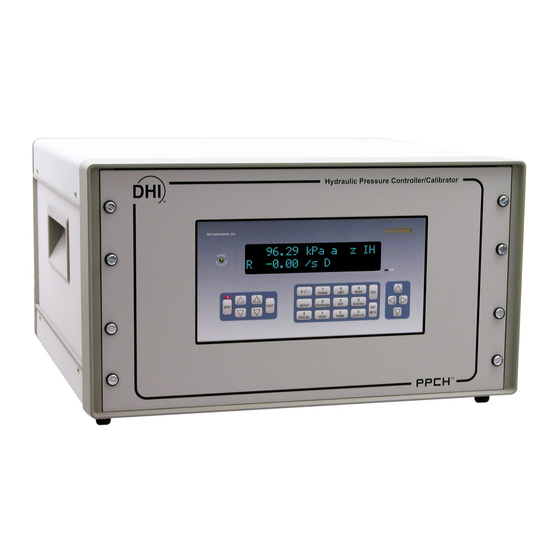
FRONT AND REAR PANELS 2.3.2.1 FRONT PANEL 1. Ready/Not Ready Indicator 4. Cursor control keys 2. Display 5. Multi-function keypad 3. Remote activity indicator 6. Direct pressure control keys Figure 1. Front panel Page 7 © 2009 DH Instruments, a Fluke Company... -
Page 18: Rear Panel
(see Section 7.3). Connect the cable to the PPCH rear panel connection labeled REMOTE ENTER. Activating the switch is equivalent to pressing the [ENT/SET P] key on the front panel (see Section 3.1.4). © 2009 DH Instruments, a Fluke Company Page 8... -
Page 19: Connecting Pneumatic Power (Drive Port)
The PPCH is shipped with its internal reservoir filled with PPCH’s working fluid. To operate without an external reservoir, the internal reservoir attachments must be installed on the PPCH rear panel. These are included with the PPCH accessories (see Table 2). Page 9 © 2009 DH Instruments, a Fluke Company... - Page 20 The PFA reservoir fill tube is delivered with a red plug with a center pull tab installed. This plug can be used after the tube is installed to cover the opening and reduce evaporation of the fluid. The plug is vented. © 2009 DH Instruments, a Fluke Company Page 10...
-
Page 21: External Reservoir
The top of the tube defines the fluid head applied to the PPCH Q-RPT when the PPCH is vented (see Section 5.6.2, Figure 20). Page 11 © 2009 DH Instruments, a Fluke Company... -
Page 22: Reservoir Return Settings
Refer to Table 4 for correct reservoir return settings and other conditions when using the internal reservoir alone or an external reservoir. Also see Section 2.3.6 for internal and external reservoir setups. © 2009 DH Instruments, a Fluke Company Page 12... -
Page 23: Installing Pump Drive Out Gas Exhaust Filter
Installing the exhaust filter/muffler Figure 5. Page 13 © 2009 DH Instruments, a Fluke Company... -
Page 24: Connecting To Other Devices
Q-RPT as direct as possible favors good pressure control. As distance, volumes and restrictions between the PPCH TEST port and the remote Q- RPT increase, the possibility of difficulty with pressure control when using the external Q-RPT increases. © 2009 DH Instruments, a Fluke Company Page 14... - Page 25 PPCH COM2 > 1st RPM4 COM1; 1st RPM4 COM2 > 2nd RPM4 COM1 See the RPM4 Operation and Maintenance Manual for additional information on RPM4 RS232 communications and COM port settings. Page 15 © 2009 DH Instruments, a Fluke Company...
-
Page 26: Connecting To A Pg7302 Piston Gauge
(standard pin-to-pin DB-9M to DB-9F RS232) and is connected to the correct communications ports. See the PG7302 Operation and Maintenance Manual for additional information on PG7302 RS232 communications and COM port settings. © 2009 DH Instruments, a Fluke Company Page 16... -
Page 27: Connecting To A Device Under Test (Test Port)
It is recommended that the low security level be maintained at all times and password protection be implemented if control over setting of security levels is desired. Page 17 © 2009 DH Instruments, a Fluke Company... -
Page 28: Turn Off Absolute Measurement Mode
1.2.2.1, 1.2.2.2). Remember to consider that head pressures can be significant with liquids (see Section 3.3.7). If the Q-RPTs do not agree within tolerances, the PPCH or RPM4 Q-RPT may need calibration or repair. © 2009 DH Instruments, a Fluke Company Page 18... -
Page 29: Checking Gauge Mode Pressure Measurement
PCH was not already set to dynamic control mode, wait 5 minutes for the thermal pressure controller to stabilize. Press [ENT]. Key in a target pressure within the active range and press [ENT] again (see Section 3.3.10). Page 19 © 2009 DH Instruments, a Fluke Company... -
Page 30: Storage And Shipping
Remove the internal reservoir accessories if they have been installed (see Section 2.3.6.1). Pack PPCH carefully being sure to use packing materials appropriate for shipment of a delicate instrument weighing approximately 50 kg (110 lb.). If available, use the original packing materials. © 2009 DH Instruments, a Fluke Company Page 20... -
Page 31: O P E R A T I O
PPCH has a screen saver function which causes the display to dim if no key is pressed for 10 minutes. Pressing a key restores full power to the display. The screen saver time can be changed or screen saving can be completely suppressed (see Section 3.5.5.1). Page 21 © 2009 DH Instruments, a Fluke Company... -
Page 32: Table 5. Main Run Screen Display Fields
<M>: Control mode is monotonic <R>: Control mode is rate <C> is appended to the control character if control limits are custom Control character(s) flash when PPCH is actively controlling © 2009 DH Instruments, a Fluke Company Page 22... -
Page 33: Function / Data Keypad Layout And Protocol
RANGE from the MAIN RUN screen. Pressing the [ ], [ ], [ ] and [ ] keys allows reverse, forward and up, down cursor movement when editing data entry or moving in menus. Page 23 © 2009 DH Instruments, a Fluke Company... -
Page 34: Direct Pressure Control Keys
Monotonic pressure control active: No effect. • Ramp control active: No effect. Pressing the up and down pressure jog keys ([ ] and [ ])simultaneously is a shortcut to the jog step size adjustment menu. © 2009 DH Instruments, a Fluke Company Page 24... -
Page 35: Remote [Ent/Set P] (Foot)Switch
The inlet valve is a pressure balanced needle valve whose needle position is controller by a stepper motor and belt drive. The inlet valve provides very high precision control of the liquid Page 25 © 2009 DH Instruments, a Fluke Company... - Page 36 TEST port. It is minimally effective when there are leaks in the test system or the test volume is large. PPCH automatically determines whether conditions are appropriate to use TPC and runs an automated routine to determine the test volume. This routine is initiated automatically when needed. © 2009 DH Instruments, a Fluke Company Page 26...
-
Page 37: Figure 9. Pressure Control System Schematic
20. Pump drive out vent port and filter/muffler Reservoir return valve 10. EXTERNAL return port 21. Two-way hydropneumatic pump cutoff valve 22. Pump drive air pressure transducer 11. Outlet valve, servo-controlled Figure 9. Pressure control system schematic Page 27 © 2009 DH Instruments, a Fluke Company... -
Page 38: Automated Pressure Control
]. [ENT/Set P] does NOT abort control in monotonic mode. When control is idle (measure mode), a Ready condition occurs any time the pressure stability test is met (see Section 3.2.3). © 2009 DH Instruments, a Fluke Company Page 28... -
Page 39: Dynamic Control
(pressure inside the control hold limit), the measured pressure equals the target pressure. For this reason, when the pressure is Ready in dynamic control mode, the measured pressure display is equal to the target pressure. Page 29 © 2009 DH Instruments, a Fluke Company... -
Page 40: Static Control
See Table 10 for default hold limit values and Section 3.4.6 to customize the hold limit. Figure 12. Static pressure control operation © 2009 DH Instruments, a Fluke Company Page 30... -
Page 41: Monotonic Control
(UL) is reached (see Section 3.4.4). If the ramp rate exceeds the specified target rate or changes sign, a Not Ready condition occurs. See Table 10 for default pressure and ramp rate target limit values and Section 3.4.6 to customize the limits. Page 31 © 2009 DH Instruments, a Fluke Company... -
Page 42: Ramp Control
3.4.4). If the rate is outside of the rate hold limit, a Not Ready condition occurs. See Table 10 for default target rate and hold limit values and Section 3.4.6 to customize the hold limit. © 2009 DH Instruments, a Fluke Company Page 32... -
Page 43: Figure 16. Ramp Pressure Control Operation
Figure 17 illustrates Ready/Not Ready operation in ramp control mode. Figure 17. Ready/Not Ready in ramp pressure control mode *Note that Figure 16 plots rate of change of pressure, not pressure. Page 33 © 2009 DH Instruments, a Fluke Company... -
Page 44: Pressure Ready/Not Ready
ΔP atm,0 Dynamic compensation for atmospheric pressure uses ΔP to correct the value of P offset,G thus always compensating real time for changes in atmospheric pressure: - ΔP gauge offset,G © 2009 DH Instruments, a Fluke Company Page 34... -
Page 45: Multiple Internal And External Q-Rpts
PPCH’s MAIN RUN screen and most other screens (see Section 3.1.1). See Table 6 for position designation protocol for the Q-RPTs available in a PPCH system. Page 35 © 2009 DH Instruments, a Fluke Company... -
Page 46: Multipe Ranges (Q-Rpts, Autorange And Infinite Ranging)
See Table 7 for a listing of PPCH adjustments and settings and whether they are range, Q-RPT or system specific. © 2009 DH Instruments, a Fluke Company Page 36... -
Page 47: Fluid Reservoir Low Level Warning
The status of the reservoir low level warning may also be viewed using [SPECIAL], <7internal>, <3pump>, <2level> (see Section 3.5.7.3.2). The status of the reservoir low level warning can be determined by remote command over the IEEE-488 or RS232 interface (see Section 4.4.3). Page 37 © 2009 DH Instruments, a Fluke Company... -
Page 48: Operation With A Pg7000 Piston Gauge
12V drivers Input a pressure control set point Set up and run automated test command from the run screen. sequences. ENTER values when editing. © 2009 DH Instruments, a Fluke Company Page 38... -
Page 49: Direct Function Keys
Range full scale limits are given in the pressure unit that is currently active for that range. Change the active unit (see Section 3.3.1) to display the range limits in a different unit. Page 39 © 2009 DH Instruments, a Fluke Company... -
Page 50: Unit]
The default units available depend on whether the PPCH was originally configured as an SI or US version. The [UNIT] key contents can be customized by the user to any configuration of six units (see Section 3.5.6). © 2009 DH Instruments, a Fluke Company Page 40... -
Page 51: Mode]
PPCH supports simple, one-step switching between two measurement modes: Absolute Measures pressure relative to vacuum (zero is hard vacuum). Range is from zero absolute to full scale. Minimum set pressure is atmospheric pressure (vented). Page 41 © 2009 DH Instruments, a Fluke Company... -
Page 52: Autorange]
AutoRange or erased when another range is selected or PPCH power is turned OFF. Use [AutoTest], <1QDUT> to AutoRange PPCH based on DUT tolerance (see Section 3.3.6.2). © 2009 DH Instruments, a Fluke Company Page 42... -
Page 53: Table 9. Settings Made By Autorange
A140M X1H 100g/100a Pressure unit of measure specified in AutoRange. AutoRange full scale pressure in gauge mode and absolute mode if available. Shows gauge mode if absolute is OFF for the Q-RPT. Page 43 © 2009 DH Instruments, a Fluke Company... -
Page 54: Rpt]
PPCH to be viewed. Use [RPT] to update the PPCH system configuration if you connect and disconnect Q-RPTs without cycling PPCH power. See Section 2.3.9.1 for information on hooking up external Q-RPTs to a PPCH system. © 2009 DH Instruments, a Fluke Company Page 44... - Page 55 PPCH COM2 > 1 RPM4 COM1; 1 RPM4 COM2 > 2 RPM4 COM1 See the RPM4 Operation and Maintenance Manual for additional information on RPM4 RS232 communications and COM port settings. Page 45 © 2009 DH Instruments, a Fluke Company...
-
Page 56: Autotest]
To run an AutoTest press [AutoTest] from the MAIN RUN screen. Run an AutoTest: The display is: 1Quick 2QDUT Select the test type desired. See Section 3.3.6.1 for Quick Test or Section 3.3.6.2 for QDUT Test. © 2009 DH Instruments, a Fluke Company Page 46... -
Page 57: Quick Autotest
This selection determines the size of the pressure increment in terms of % of the span of the test. The pressure sequence will run in pressure steps of (span x increment %) ending with the uneven increment if applicable. Page 47 © 2009 DH Instruments, a Fluke Company... - Page 58 Ready condition has occurred at the increment and the countdown timer has expired. If the sequence was set up with <Next increment on ENTER>. Press [ENT] to continue to the next increment. © 2009 DH Instruments, a Fluke Company Page 48...
-
Page 59: Qdut Autotest
Select the measurement mode of the DUT that is being tested. If the desired measurement mode is not available, the QRPTs available to PPCH do not support the measurement mode or it is turned off. Page 49 © 2009 DH Instruments, a Fluke Company... - Page 60 AutoRange range. Enter the DUT tolerance and press [ENT]. The display is: Test increment: 20.0%FS Entry field for sequence pressure increment in % of full scale. Recalls last value entered. © 2009 DH Instruments, a Fluke Company Page 50...
- Page 61 Perform any operations that are needed before running the test such as making connections or exercising the DUT. The PPCH direct pressure control keys are active to allow pressure adjustment (see Section 3.1.3). When ready to begin the test, press [ENT]. Page 51 © 2009 DH Instruments, a Fluke Company...
-
Page 62: Head]
To cause a pressure fluid head correction to be added to or subtracted from the pressure measured by the PPCH reference pressure transducer in order to predict the pressure at a height other than the PPCH’s reference level. © 2009 DH Instruments, a Fluke Company Page 52... - Page 63 • In absolute measurement mode, enter the difference between the PPCH reference level (marked on the rear panel of the PPCH) and the DUT height as the head height in [HEAD]. Page 53 © 2009 DH Instruments, a Fluke Company...
-
Page 64: Prime]
Ideally, devices are filled with liquid prior to be being connected to PPCH. The PRIME and PURGE routines are both intended to assist in safely © 2009 DH Instruments, a Fluke Company Page 54... -
Page 65: 1Prime
If the pressure reaches 0.5 MPa (75 psi), the priming routine ends and <Prime completed> is displayed To leave the priming routine press [ESC] or [ENT] from the <Prime completed> screen. Consider purging after priming (see Section 3.3.8.2). Page 55 © 2009 DH Instruments, a Fluke Company... -
Page 66: 2Purge
The LEAK CHECK function allows a leak check time to be set. The total pressure change and the average rate of change over the leak check time are calculated and displayed. © 2009 DH Instruments, a Fluke Company Page 56... - Page 67 From the leak check results screen, press [ENT] to repeat the leak test. Press [ESC] to return to leak check main menu and exit to the MAIN RUN screen. Page 57 © 2009 DH Instruments, a Fluke Company...
-
Page 68: Ent/Set P] (Set Pressure Automatically)
For best results, wait 5 minutes with the PPCH vented before controlling pressure when changing to or from dynamic control mode. This is to allow time for the PPCH thermal pressure control unit to respond and stabilize. © 2009 DH Instruments, a Fluke Company Page 58... -
Page 69: Static Control Mode, [Ent/Set P]
3.1.3). These keys also jog the target value when in the ENTER target value screen. 3.3.10.2 STATIC CONTROL MODE, [ENT/SET P] If the PPCH is not set for static control, use SPECIAL, <6control>, <2mode> to select static control mode. Page 59 © 2009 DH Instruments, a Fluke Company... - Page 70 PPCH is waiting for pressure stability to jog the pressure by the pressure step value (see Section 3.1.3). These keys also jog the target value when in the ENTER target value screen. © 2009 DH Instruments, a Fluke Company Page 60...
-
Page 71: Monotonic Control Mode, [Ent/Set P]
PPCH continues controlling following monotonic pressure control protocol (see Section 3.2.2.4) until automated pressure control is interrupted. If PPCH is unable to control pressure or appears to control pressure poorly, see Section 6 to troubleshoot. Page 61 © 2009 DH Instruments, a Fluke Company... -
Page 72: Ramp Control Mode, [Ent/Set P]
(see Section 3.2.2.5) until automated pressure control is interrupted. If PPCH is unable to control pressure or appears to control pressure poorly, see Section 6 to troubleshoot. © 2009 DH Instruments, a Fluke Company Page 62... -
Page 73: Interrupting Automated Pressure Control
PPCH can set. When zero absolute is given as a pressure target, the pressure actually measured by the PPCH after the ready condition occurs must be read back rather than assuming a specific pressure value has been set. Page 63 © 2009 DH Instruments, a Fluke Company... -
Page 74: Setup]
80g/80a Pressure unit of measure of the range to be saved. Full scale pressure of the range to be saved in gauge mode and absolute mode if available. © 2009 DH Instruments, a Fluke Company Page 64... -
Page 75: Deleting Autorange Ranges
150 X 0.001 % = 0.0015 which is rounded down to 0.001 MPa. Default resolution is 10 ppm of active range span. Resolution is set automatically by AutoRange (see Section 3.3.4). Page 65 © 2009 DH Instruments, a Fluke Company... -
Page 76: 3Jog
Press [ESC] to return to the MAIN RUN screen with no change to the jog step size. Pressing [ ] and [ ] simultaneously is a short cut to the <Jog step size:> menu. © 2009 DH Instruments, a Fluke Company Page 66... -
Page 77: 4Ul> (Upper Limit)
For example, if you set 100 MPa as the upper limit in gauge mode, the upper limit will not be 100 MPa in absolute mode of the same range. Page 67 © 2009 DH Instruments, a Fluke Company... -
Page 78: Over Pressure Function
PPCH with head, AutoZ and range status as well as an indication of whether the reading was in or out of tolerance and the test point number over the total number of test points in the QDUT sequence. © 2009 DH Instruments, a Fluke Company Page 68... -
Page 79: 6Control
± 0.01 % of the active range to ± 0.05 % of the active range decreases the time required to set a pressure since the limit within which the pressure must Page 69 © 2009 DH Instruments, a Fluke Company... -
Page 80: 1Limits> (Custom Control Parameters)
[SETUP], <6control>, <1limits> from the MAIN RUN screen. The display is depends upon the active control mode. To reset default control parameters for a range and control mode, select the control mode using [SETUP], 6control, 2mode. © 2009 DH Instruments, a Fluke Company Page 70... - Page 81 1.000 MPa active target limit. Active control mode (<M> for monotonic). Edit the target limit value if desired and press [ENT] to view the monotonic ramp rate limit. The next display is: Page 71 © 2009 DH Instruments, a Fluke Company...
-
Page 82: 2Mode
1standard 2hi volume Select the desired dynamic control mode type. The default is <1standard>. Making a control mode selection activates the control mode, sets default control parameters for that control mode. © 2009 DH Instruments, a Fluke Company Page 72... -
Page 83: Turning-Off Custom Control Parameters
Pressing [ENT] while in the external drivers menu causes a menu to appear that allows selection of whether the driver actuation by selecting the driver number will be <1momentary> or <2toggle>. Page 73 © 2009 DH Instruments, a Fluke Company... -
Page 84: Special]
The AutoZero function uses three values: 1. P : The pressure value indicated by the AutoZ reference, the device that is acting as std,0 the reference relative to which to offset the Q-RPT. © 2009 DH Instruments, a Fluke Company Page 74... - Page 85 AutoZ updates (see Section 3.2.4). The measured gauge pressure is calculated using ΔP to correct the value of P offset.G - ΔP gauge offset.G Page 75 © 2009 DH Instruments, a Fluke Company...
-
Page 86: Table 11. Autoz On And Off
In absolute measurement mode: Take care to properly consider fluid heads on the Q-RPTs and the AutoZ reference. OPERATION The AutoZ function and values are Q-RPT AND measurement mode (absolute, gauge) specific. © 2009 DH Instruments, a Fluke Company Page 76... -
Page 87: Edit Autoz
In normal day to day operation, the value of the AutoZ offset, P offset should be changed using the run AutoZ function (seen Section 3.5.1.2) in absolute measurement mode or automatically in gauge modes. Before editing P , see Section 3.5.1, PRINCIPLE. offset Page 77 © 2009 DH Instruments, a Fluke Company... -
Page 88: Run Autoz
Press [ENT] to activate the new value of Old P : 0.0 Pa offset or [ESC] to start over with entry of a offset New P : 675 Pa offset new AutoZ reference (P ) value. std,0 © 2009 DH Instruments, a Fluke Company Page 78... -
Page 89: 2Remote
A self test is supplied for RS-232 communications. The self test allows verification that the PPCH RS232 ports (COM1 and COM2) are operating properly and that a valid interface cable is being used. Page 79 © 2009 DH Instruments, a Fluke Company... -
Page 90: 1Com1, 2Com2
The cursor is on the active format. Select <1classic> to activate the classic command format or <2enhanced> for the enhanced format. Selecting a format resets the IEEE-488 interface and puts it into an idle state. © 2009 DH Instruments, a Fluke Company Page 80... -
Page 91: 5Rs232 Self-Test
Select the gas or liquid species. The liquid selection <3User>, is to create a custom liquid with a user entered density. Use [HEAD] to set a fluid head height if desired (see Section 3.3.7). Page 81 © 2009 DH Instruments, a Fluke Company... -
Page 92: 4Reset
<1SETS> PURPOSE Sets most general operating parameters back to default values. Does not affect calibration coefficients, remote interfaces or AutoRange ranges. The Reset – Sets resets are itemized in Table 12. © 2009 DH Instruments, a Fluke Company Page 82... -
Page 93: 2Units
PPCH calibration and could cause it to make out of tolerance measurements. Clears all user values affecting the calibration of Q-RPTs, utility sensor and the on-board barometer. Does not clear factory coefficients. The Reset – Cal resets are itemized in Table 13. Page 83 © 2009 DH Instruments, a Fluke Company... -
Page 94: 5All
3.5.5 <5PREF> PURPOSE To access a menu of PPCH operational preferences and functions. OPERATION 1ScrSvr 2sound 3time To access the PREF menu press [SPECIAL], <5pref>. The display is: 4ID 5level © 2009 DH Instruments, a Fluke Company Page 84... -
Page 95: 1Scrsvr
Select <1none> to suppress the valid key press tone. The sound function only affects the valid key press tone. The invalid key press and other tones cannot be suppressed. See Section 3.1.5 for a complete listing of PPCH sounds. Page 85 © 2009 DH Instruments, a Fluke Company... -
Page 96: 3Time
The ID can be set remotely from a computer which is quite a bit more convenient than entering characters from the keyboard (see Section 4.4, ID command). The ID is not cleared or reset by any RESET function (see Section 3.5.4). © 2009 DH Instruments, a Fluke Company Page 86... -
Page 97: 5Level> (Security)
The security levels are structured to support typical levels of operation as shown in Table 15. Specifically, the security levels prevent execution of the functions accessed by the key strokes marked by “•”: Page 87 © 2009 DH Instruments, a Fluke Company... -
Page 98: Table 15. Security Levels
• • • [SPECIAL], <8cal>, <2edit> under any selection [SPECIAL], <9log>, view • • • • [SPECIAL], <9log>, clear log • Remote communications disabled “•” indicates the function/menu is NOT accessible. © 2009 DH Instruments, a Fluke Company Page 88... -
Page 99: 6Punit
Service Center (see Table 31). The factory secondary password is different for all PPCH’s and changes each time it is used. 3.5.6 <6PUNIT> PURPOSE To customize the selection of pressure units of measure that are available in the [UNIT] key menu. Page 89 © 2009 DH Instruments, a Fluke Company... -
Page 100: Table 16. Unit Function - Available Units Of Measure
The user defined unit label can be customized to any alphanumeric, four character label using the remote command “UDU” (see Section 4.4). See Section 7.2.1 for the pressure unit conversion factors used by PPCH. © 2009 DH Instruments, a Fluke Company Page 90... -
Page 101: 7Internal
(see Section 3.2.4) PPCH measurement uncertainty does not depend on the measurement uncertainty of the on-board barometer unless the barometer is used as a reference for AutoZ of Q-RPTs in absolute measurement mode. Page 91 © 2009 DH Instruments, a Fluke Company... -
Page 102: 3Pump
By default, when a low reservoir condition is detected, PPCH aborts pressure control and will not accept any local or remote commands to adjust pressure. Pressure control is prevented to protect the PPCH hydropneumatic pump which © 2009 DH Instruments, a Fluke Company Page 92... - Page 103 The pump output pressure is calculated using the pump drive pressure and the pump ratio. The required drive pressure, is the drive pressure needed to achieve the required pump output pressure for a given PPCH model. Page 93 © 2009 DH Instruments, a Fluke Company...
-
Page 104: 8Cal
PPCH records to a log each time one of the following events occurs: • Pmax! of an internal PPCH Q-RPT or utility sensor is exceeded (see Section 3.4.4.1). • A memory fault occurs. © 2009 DH Instruments, a Fluke Company Page 94... - Page 105 After the last log has been viewed, the option to clear the log, <1no>, <2yes> is presented. Use <2yes> to remove all entries from the log. Use <1no> to continue without altering the log. To leave the log, use [ESC]. Page 95 © 2009 DH Instruments, a Fluke Company...
- Page 106 PPCH™ OPERATION AND MAINTENANCE MANUAL © 2009 DH Instruments, a Fluke Company Page 96...
-
Page 107: Overview
This pin accepts serial data from the host computer. This pin is the common return for the TxD and RxD signals. IBM PC/XT DB-9F IBM PC/XT DB-9M TO PPCH DB9F CONNECTIONS CONNECTION DB-25M DB-9F DB-9M DB-9F Page 97 © 2009 DH Instruments, a Fluke Company... -
Page 108: Ieee-488
The PPCH program message set is compatible with the PPC3 program message set. Some PPC3 commands are not fully supported due to functional differences between PPCH and the PPC3 and PPCH includes some commands specific to PPCH hardware that PPC3 does not support. © 2009 DH Instruments, a Fluke Company Page 98... -
Page 109: Classic Program Message Format
“?” immediately after the command. You also may send multiple program messages at once by separating each program message with a semicolon. The commands are queued and executed in as Page 99 © 2009 DH Instruments, a Fluke Company... -
Page 110: Using Query Type Commands
“PR?”, “PRR?”, “SR?”, “ATM?”, “RATE?”: Up to 2 seconds. “RPT”, “ARANGE”: Up to 10 seconds The syntax for using a QUERY program message is listed next to the keyword “Query:” in each program message summary in Section 4.4.4. © 2009 DH Instruments, a Fluke Company Page 100... -
Page 111: Commands
Read or set the current time of day. Read the current target pressure. TPCCFG Start or check the status of a previously started volume determination (TPC configuration) (planned command as of PPCH Ver. 1.01f) Page 101 © 2009 DH Instruments, a Fluke Company... -
Page 112: Error Messages
“Argument not allowed” ERR #46 “Argument cannot be negative” ERR #52 “Command obsolete” ERR #53 “Not Available” ERR# 54 “Not ready” ERR# 55 “Hardware malfunction” (fluid reservoir low, will not set pressure) © 2009 DH Instruments, a Fluke Company Page 102... -
Page 113: Program Message Description Overview
In either case, the “ERR” or “ERR?” program message can be used to occurred. retrieve a text description of the error. See Also Indicates related command (“----“) and refers to manual sections giving detail on PPCH operation corresponding to the program message. Page 103 © 2009 DH Instruments, a Fluke Company... -
Page 114: Program Message Descriptions
Sent: “#VER” (classic) Reply: “DH INSTRUMENTS, a Fluke Company PPCH si A20M Ver1.00 ” This example assumes that a second PPCH’s COM1 port is connected to the PPCH COM2 port. This example gets the version of the second PPCH. See Also “PASSTHRU”, “COM2”... - Page 115 (always absolute). This measurement is followed by the units text. Example Query sent: “ATM?” (enhanced) Reply: “97.12348 kPaa” Example Sent: “ATM” (classic) Reply: “97.12384 kPaa” See Also 3.5.7.2 Page 105 © 2009 DH Instruments, a Fluke Company...
- Page 116 (No reply if GPIB-488) Example Cmd sent: “COM1? 9600,N,8,1” (enhanced) Reply: “9600,N,8,1” Example Sent: “COM1=9600,N,8,1” (classic)) Reply: “9600,N,8,1” Errors ERR# 7: Missing or improper program message argument(s). See Also “#”, “PASSTHRU” 4.2.1.1 © 2009 DH Instruments, a Fluke Company Page 106...
- Page 117 “DF=1” (classic) Reply: “DF=1” Errors ERR# 6: The n argument is a ‘0’ or a ‘1’. ERR# 55: Hardware malfunction, low reservoir See Also “IF” , “DS”, “IS”, “IP”, “DP”, 3.2.1 Page 107 © 2009 DH Instruments, a Fluke Company...
- Page 118 Example Query sent: “ERR?” (enhanced): Reply: “Numeric argument missing or out of range” Example Sent: “ERR” (classic) Reply: “Numeric argument missing or out of range” See Also 4.4.2 © 2009 DH Instruments, a Fluke Company Page 108...
- Page 119 (No reply if GPIB-488) Example Cmd sent: “HS? .1” (enhanced) Reply: “0.100 MPa” Example Sent: “HS=0.1” (classic) Reply: “0.100 MPa” Errors ERR# 6 The ‘limit’ argument was invalid. See Also “HS%”, “MODE” 3.2.2.2, 3.2.2.4 Page 109 © 2009 DH Instruments, a Fluke Company...
- Page 120 Reply: “IF=1” Errors ERR# 6: The n argument is a ‘0’ or a ‘1’. ERR# 55: Hardware malfunction, fluid reservoir is low. See Also “DF” , “DS”, “IS”, “IP”, “DP”, 3.2.1 © 2009 DH Instruments, a Fluke Company Page 110...
- Page 121 Example Cmd sent: “LOCAL” (enhanced) Reply: “LOCAL” (no reply if IEEE-488) Example Cmd sent: “LOCAL?” (enhanced) Reply: “LOCAL” Example Sent: “LOCAL” (classic) Reply: “LOCAL” See Also “REMOTE” Page 111 © 2009 DH Instruments, a Fluke Company...
- Page 122 “A” Example Cmd sent: “MMODE=G” (enhanced) Reply: “G” Errors ERR# 6: Invalid argument text. ERR# 20: Absolute mode not available on absolute RPT with absolute use disabled. See Also “UNIT” 3.3.3 © 2009 DH Instruments, a Fluke Company Page 112...
- Page 123 The ‘#’ command can also be used for this sort of operation, but with fewer options available. Example Cmd sent: “PASSTHRU=VER” (enhanced) Reply: “COM2:DH INSTRUMENTS, A FLUKE COMPANY PPCH VER1.01a” Reply: “COM2:” (If the COM2 buffer is empty) Example Sent: “PASSTHRU=VER”...
- Page 124 This can take up to 1.5 seconds. Example Query sent: “PR?” (enhanced) Reply: “R 19.367 MPa a” Example Query sent: “PR” (classic) Reply: “R 19.367 MPa a” See Also “PRR”, “QPRR”, “SR” 3.1.1, 3.2.2 © 2009 DH Instruments, a Fluke Company Page 114...
- Page 125 Pressure has exceeded maximum limits. ERR#18 This command not valid in “rate” generation mode. ERR# 55 Hardware malfunction, reservoir level low. See Also “PR”, “PRR”, “STAT”, “SR”, “QPRR”, “RS” 3.2.2, 3.3.10, 3.2.1 Page 115 © 2009 DH Instruments, a Fluke Company...
- Page 126 The PPCH drive pump timer keeps track of how long the pump has has been pressurized since being serviced. Example Cmd sent: “PUMPHOURS?” (enhanced) Reply: “22” Example Sent: “PUMPHOURS” (classic) Reply: “22” See Also 3.5.7.3.4 © 2009 DH Instruments, a Fluke Company Page 116...
- Page 127 Errors ERR# 6: Invalid Rng argument. ERR# 22: System must be vented for the requested operation. ERR# 38: The selected RPT is not available. See Also “ARANGE”, “RPT” 3.2.6, 3.3.1, 3.3.4 Page 117 © 2009 DH Instruments, a Fluke Company...
- Page 128 PPCH power. A transition from remote to local operation aborts any current pressure control. Example Cmd sent: “REMOTE” (enhanced) Reply: “REMOTE” (no reply if IEEE-488) Example Cmd sent: “REMOTE?” (enhanced) Reply: “REMOTE” Example Sent: “REMOTE” (classic) Reply: “REMOTE” See Also “LOCAL” © 2009 DH Instruments, a Fluke Company Page 118...
- Page 129 Example Cmd sent: “RESLOACT 1” (enhanced) Reply: “1” Example Sent: “RESLOACT=1” (classic) Reply: “RESLOACT=1” Errors ERR# 6: The argument was other than a ‘0’ or a ‘1’. See Also “RESLEV” 3.5.7.3.2 Page 119 © 2009 DH Instruments, a Fluke Company...
- Page 130 “10.0 %/s”(No reply from GPIB-488) Example Cmd sent: “RL%? 10” (enhanced) Reply: “10.0 %/s” Example Sent: “RL%=10” (classic) Reply: “10.0 %/s” Errors ERR# 6 The argument was invalid. See Also “RL” 3.2.2.5, 3.4.6.1 © 2009 DH Instruments, a Fluke Company Page 120...
- Page 131 (Get information on RPT in ext RPM4, Lo position) (classic) Reply: “A100M, IH, 82345, 100, 100,A” Errors ERR# 4: RPT not previously found ERR# 10: Invalid prefix. See Also “ARANGE”, “COM2” 3.3.5, 3.2.5 Page 121 © 2009 DH Instruments, a Fluke Company...
- Page 132 Remarks The PPCH is serialized. The serial number can be read using this program message. Example Query sent: “SN?” (enhanced) Reply: “321” Example Sent: “SN” (classic) Reply: “321” See Also 3.5.5.4 © 2009 DH Instruments, a Fluke Company Page 122...
- Page 133 (No reply from GPIB-488) Example Cmd sent: “SS? .1” (enhanced) Reply: “0.100 MPa/s” Example Sent: “SS=.1” (classic) Reply: “0.100 MPa/s” Errors ERR# 6 The argument was invalid. See Also “HS” 3.2.2.2, 3.2.2.3, 3.2.2.4, 3.4.6.1 Page 123 © 2009 DH Instruments, a Fluke Company...
- Page 134 ERR# 54: The pressure is below the minimum of 1 Mpa (reply to a command only) ERR# 22: The pressure is not stable enough (reply to query only) See Also “ABORT” 3.5.7.1 © 2009 DH Instruments, a Fluke Company Page 124...
- Page 135 “UDU MYUN, .001” (enhanced) Reply: “MYUN, 0.001000” (No reply if GPIB-488) Example Cmd Sent: “UDU? MYUN, .001” (enhanced) Reply: “MYUN, 0.001000” Example Sent: “UDU=MYUN, .001” (enhanced) Reply: “MYUN, 0.001000” See Also 3.5.6, 3.3.2 Page 125 © 2009 DH Instruments, a Fluke Company...
- Page 136 Sent: “UNIT=kPaa” (classic) Reply: “kPa a” Sent: “UNIT=InWag, 4” Reply: “inWag, 4” Errors ERR# 7: The unit is invalid. ERR# 6: The ref is invalid. See Also “MMODE”, “MODE” 3.3.2, 3.3.3 © 2009 DH Instruments, a Fluke Company Page 126...
- Page 137 The software version of the PPCH can be read. This is useful for checking for the presence of the PPCH and for reference purposes. It indicates the internal RPT(s) and software version. Example Query sent: “VER?” (enhanced) Reply: “DH INSTRUMENTS, A FLUKE COMPANY PPCH us A100M/A20M Ver1.00 ” (US version) Example Query sent: “VER?” (classic) Reply: “DH INSTRUMENTS, A FLUKE COMPANY PPCH si A100M/A20M Ver1.00...
-
Page 138: Status Reporting System
OPER RQS/MSS ERROR (128) (64) (32) (16) This register is affected by the PPCH reply output queue, the Error Queue, the Standard Event Status register and the Ready Event Status register. © 2009 DH Instruments, a Fluke Company Page 128... -
Page 139: Figure 18. Status Register Schematic
Indicates that at least one command error message is waiting in the PPCH IEEE- 488 error message queue. Use the “ERR?” query to get this message. Ready Summary Bit 0 (1) Indicates that an enabled bit in the Ready Status Register became set. Page 129 © 2009 DH Instruments, a Fluke Company... -
Page 140: Standard Event Register
This register can be read using the “*RSR?” query, Each of these status bits can set the RSB bit of the Status Byte Register, causing a SRQ to occur IF the RSB bit is enabled to do so. © 2009 DH Instruments, a Fluke Company Page 130... -
Page 141: Ieee Std. 488.2 Common And Status Program Messages
Remarks This program message clears the following events and status registers: Standard Byte Register (STB) Standard Event Status Register (ESR) Error Queue Pending OPC operations Example Sent: “∗CLS” (classic) Reply: none Page 131 © 2009 DH Instruments, a Fluke Company... - Page 142 This Command sets the PPCH settings to factory settings. This equivalent to a front panel executed RESET/SET. This does not affect the communications settings. Example Sent: “∗RST” (enhanced) Reply: “∗RST” (no reply if IEEE-488) See Also 3.5.4.1 © 2009 DH Instruments, a Fluke Company Page 132...
- Page 143 Read the Ready Status Register. Command “RSR?” Remarks The Ready Status Register contents are cleared after reading. The reply is in decimal numeric form. Example Sent: “RSR?” (enhanced) Reply: “6” (The MEAS and NRDY) Page 133 © 2009 DH Instruments, a Fluke Company...
- Page 144 PPCH™ OPERATION AND MAINTENANCE MANUAL © 2009 DH Instruments, a Fluke Company Page 134...
-
Page 145: Maintenance, Adjustments A N D C A L I B R A T I O
See Section 8. PREVENTIVE MAINTENANCE Preventive maintenance should be performed once a year or every 2000 hours of high pressure operation, as measured by the PPCH on-board timer (see Section 3.5.7.3.4). Page 135 © 2009 DH Instruments, a Fluke Company... -
Page 146: Table 25. Ppch Maintenance Parts
402404 New replacement pump for PPCH-140M, -200M pump, recon air driven, PP189 402402 Reconditioned replacement pump for PPCH-70M, -100M pump, recon air driven, PP189-2 402401 Reconditioned replacement pump for PPCH-140M, -200M © 2009 DH Instruments, a Fluke Company Page 136... -
Page 147: Calibration Of Quartz Reference Pressure Transducers (Q-Rpts)
CAL function (see Section 5.3.7). PA and PM values are automatically edited when CalTool software is used and the results are activated. Page 137 © 2009 DH Instruments, a Fluke Company... -
Page 148: As Received And As Left Data
This does not mean that the PPCH has not been calibrated. In the original factory calibration, privileged factory coefficients are used for calibration with the user PA and PM set to zero and 1. © 2009 DH Instruments, a Fluke Company Page 138... -
Page 149: Equipment Required
5 minutes, returning to atmosphere (vented), dwelling for twenty minutes. A dwell time after setting the pressure of at least 90 seconds before taking data at each point is recommended. Page 139 © 2009 DH Instruments, a Fluke Company... -
Page 150: Turning Off Absolute Measurement Mode For A Q-Rpt
Turning absolute mode operation ON and OFF for a Q-RPT occurs in the same area in which calibration coefficients are edited. To access the Q-RPT calibration editing area press [SPECIAL], <8cal> and select the desired Q-RPT. Then select <1edit> to make changes (see Section 5.3.7). © 2009 DH Instruments, a Fluke Company Page 140... -
Page 151: Q-Rpt Calibration Using Caltool For Rpts Software
PPCH has not been calibrated. In the original factory calibration, privileged factory coefficients are used for calibration with the user PA and PM set to zero and 1. Page 141 © 2009 DH Instruments, a Fluke Company... - Page 152 PPCH may also use external Q-RPTs mounted in RPM4 Reference Pressure Monitors. Viewing and adjustment of RPM4 calibration information is performed locally on the RPM4, not through PPCH (see the RPM4 Operation and Maintenance Manual). © 2009 DH Instruments, a Fluke Company Page 142...
-
Page 153: Q-Rpt Calibration/Adjustment Without Caltool For Rpts Software
Q-RPT used in absolute mode, edit the value of P to zero. If this is an Axxx Q-RPT and offset the calibration was performed in gauge mode, turn absolute mode OFF so that it cannot be used after the calibration. Page 143 © 2009 DH Instruments, a Fluke Company... -
Page 154: Adjustment Of On-Board Barometer
The utility sensor is not intended to serve as a pressure reference for low uncertainty, traceable measurement. It is for indication, pressure control and system maintenance functions only. PPCH measurement uncertainty when using Q-RPTs does not depend on the measurement uncertainty of the utility sensor. © 2009 DH Instruments, a Fluke Company Page 144... -
Page 155: Filling And Draining The Fluid Reservoir
FILL/DRAIN tube. In order for the PPCH internal reservoir fluid head reference level to be correct, it is necessary to drain oil until the level is below the MAX FILL line (see Section 5.6.1.2). Page 145 © 2009 DH Instruments, a Fluke Company... -
Page 156: Draining The Internal Reservoir
<Reservoir level low> on the display bottom line (see Section 3.5.7.3). If the external reservoir has been installed as recommended in Section 2.3.6.2, the reservoir level warning system is still active. © 2009 DH Instruments, a Fluke Company Page 146... -
Page 157: Draining The External Reservoir
Fluid will run out the external tank fill tube. Wait a few moments for the flow to stop. Disconnect the external tank return tube from the external tank and place it in the receptacle. When the tubes have drained, detach them from the PPCH. Page 147 © 2009 DH Instruments, a Fluke Company... -
Page 158: Purging Contaminated Fluid From The Ppch
(see Section 4.4.1). Thermal pressure control (TPC) is only used in dynamic control mode. Therefore, the volume configuration routine can only execute when standard dynamic control mode is active. © 2009 DH Instruments, a Fluke Company Page 148... - Page 159 Select <2no> to retain the old volume determination and return to the main run screen. To view the estimate of test volume currently being used by PPCH, press [SPECIAL], <7internal>, <1config>, <1volume>, <2view>. Page 149 © 2009 DH Instruments, a Fluke Company...
-
Page 160: Valve Opening Point Configuration
<2factory> to cause PPCH to load original factory valve opening point tables. This feature can be useful to return to standard conditions if a faulty VALVE CONFIG routine has been activated or the current configuration is no longer valid. © 2009 DH Instruments, a Fluke Company Page 150... -
Page 161: Accessing Ppch Mechanical Module
Further slide the chassis into the PPCH enclosure, taking care not to snag any of the wires within the PPCH. Tighten all 18 fasteners on the PPCH main rear panel. Step 2 Page 151 © 2009 DH Instruments, a Fluke Company... -
Page 162: Hydropneumatic Pump
Assure that the TEST port is NOT open. Plug the TEST port. Liquid will be driven out the TEST port during priming if it is open. Press [SPECIAL], <7internal>, <3pump>, <1prime>. © 2009 DH Instruments, a Fluke Company Page 152... -
Page 163: Priming The Pump Check Valve
Using a 5/8 in. wrench, loosen the DH500 outlet check valve fitting about 1/2 turn. A small amount of oil may be expelled. Step 8 and 9 Page 153 © 2009 DH Instruments, a Fluke Company... -
Page 164: Pump Replacement
Place the PPCH on a bench on its left side. Do not place the unit on its right side or fluid leakage may occur. Rotate the inlet supply tube and funnel to the upright position. Step 4 © 2009 DH Instruments, a Fluke Company Page 154... - Page 165 Slide the mechanical module back into the PPCH chassis (see Section 5.9). Open reservoir FILL/DRAIN valve. Purge system for 20 cycles to 75% of controller full scale, using [PRIME], <2purge> (see Section 3.3.8.2). Page 155 © 2009 DH Instruments, a Fluke Company...
-
Page 166: Pump Spool Valve Inspection Or Repair
Note orientation of this fitting. Step 2 and 6 Locate end cap and retaining clip on the end of the spool valve body. Remove retaining clip using the appropriate snap ring tool. Step 5 © 2009 DH Instruments, a Fluke Company Page 156... - Page 167 Slide the mechanical module back into the PPCH chassis (see Section 5.9). Reconnect electrical power and drive air. Power up the PPCH. Test for proper pump operation by setting pressure points (see Section 3.3.10). Page 157 © 2009 DH Instruments, a Fluke Company...
-
Page 168: Pump Inlet Filter (Liquid) Replacement
Perform pump prime procedure (see Section 5.10.1). Check filter connections for leaks. New Pump Supply Filter P/N Open reservoir FILL/DRAIN valve. 3138000 (102808) Close PPCH chassis (see Section 5.9). Step 5 © 2009 DH Instruments, a Fluke Company Page 158... -
Page 169: Leak Checking
Wait for the effects of the just completed pressure change to dissipate. This requires at least 5 minutes and may be longer if there is a large test volume connected. Page 159 © 2009 DH Instruments, a Fluke Company... -
Page 170: Localizing A Leak Within The Ppch
If the leak internal to the PPCH is not in a shutoff valve or a visible internal connection that can be tightened, it is probably in the outlet control valve (see Section 5.12.2) or another area that is not user serviceable. © 2009 DH Instruments, a Fluke Company Page 160... -
Page 171: High Pressure Vent Valve Leak
Vent the PPCH and disconnect electrical power and drive air supply. Open the PPCH chassis to gain access to the mechanical module (see Section 5.9). Loosen the high pressure vent valve bracket retaining hardware (two button head bolts). Step 5 Page 161 © 2009 DH Instruments, a Fluke Company... - Page 172 If the leak is still present, there is a leak that is not in the vent valve. Reconnect the original vent valve and proceed with additional leak testing to localize a leak within PPCH (see Section 5.11.2). © 2009 DH Instruments, a Fluke Company Page 162...
-
Page 173: Low Pressure Isolation Valve Leak
To identify the low pressure vent valve in the PPCH schematic, see Section 3.2.1, Figure 9. PPCH includes a low pressure vent valve only if it has an internal Lo Q-RPT. Page 163 © 2009 DH Instruments, a Fluke Company... - Page 174 Reconnect the original vent valve and proceed with additional leak testing to localize a leak within PPCH (see Section 5.11.2). Step 5 © 2009 DH Instruments, a Fluke Company Page 164...
-
Page 175: Valve Replacement Or Repair
Hi Q-RPT or utility sensor and disconnect the cable from the cable harness of the Hi Q-RPT or utility sensor. Remove the valve bracket retaining hardware (two button head bolts). Step 6 Page 165 © 2009 DH Instruments, a Fluke Company... -
Page 176: Control Valve Service
Quality Feedback Report at details by email to www.dhinstruments.com. The DHI flash software loading utility (WinFlash) and PPCH embedded software are available for download from DHI web site, www.dhinstruments.com. © 2009 DH Instruments, a Fluke Company Page 166... -
Page 177: Subassembly Description And Location
@ 0.35 Amps: For the supply of the micro board and driver board electronics. Internal power supply fuse not replaceable by operator: 2A, 250 V (UV 440-2 power supply). 3.15A, 250 V (NFS40-7612 power supply). Page 167 © 2009 DH Instruments, a Fluke Company... -
Page 178: Driver Board
(see Section 3.2.4). The temperature sensor is used for temperature compensation of the barometric sensor. © 2009 DH Instruments, a Fluke Company Page 168... -
Page 179: Mechanical Module
Two independent quartz elements are used. One quartz element is subjected to pressure related stress. The other quartz element is used only to monitor temperature. See Section 1.2.2.1 for Q-RPT specifications. Page 169 © 2009 DH Instruments, a Fluke Company... -
Page 180: Test Vent Valve
5.14.2.11 INLET CONTROL VALVE Highly progressive needle valve. The valve is operated by a stepping motor and drive belt. © 2009 DH Instruments, a Fluke Company Page 170... -
Page 181: 5.14.2.12 Outlet Control Valve
Factory set pneumatic regulator that regulates the pressure connected to the DRIVE port and supplies the PPCH pneumatic system for pump air drive, pneumatically operated valve actuation and reservoir pressurization for pump priming. Page 171 © 2009 DH Instruments, a Fluke Company... - Page 182 PPCH™ OPERATION AND MAINTENANCE MANUAL © 2009 DH Instruments, a Fluke Company Page 172...
-
Page 183: Table 27. Troubleshooting Guide
The custom control function has been used. selecting a control mode using the bottom line of the display and it CONTROL function. 3.4.6.2 won’t go away. Page 173 © 2009 DH Instruments, a Fluke Company... - Page 184 Examine pressure circuit and tighten fittings and inlet control valve. if necessary. 5.9 Pump high pressure seals failing as evidenced by liquid output or mist from the Replace pump. 5.10.2 pmp muffler. © 2009 DH Instruments, a Fluke Company Page 174...
- Page 185 Q-RPT. Apparent inaccurate pressure Contact DHI Authorized Service Provider. control/measure and little or no Reference transducer destroyed by response from Q-RPT or utility overpressure. Table 31 sensor. Page 175 © 2009 DH Instruments, a Fluke Company...
- Page 186 PPCH beeps rapidly ten times and/or bottom line of main run The PPCH fluid reservoir is low and in Fill reservoir immediately. 5.6 screen displays <Reservoir level danger of being empty. low>. © 2009 DH Instruments, a Fluke Company Page 176...
-
Page 187: Drivers
Driver #6 (Open Collector) Driver #7 (Open Collector) Driver #8 (Open Collector) Drivers (+ 12 V) Drivers (+ 12 V) Drivers (+ 12 V) Figure 23. Drivers connector schematic Drivers (+ 12 V) Page 177 © 2009 DH Instruments, a Fluke Company... -
Page 188: Unit Conversion
ENTER cable (DHI p/n 103128). Install the switch by connecting its two terminals to the black and white wires of the remote ENTER cable. 1. Black wire 2. White wire Figure 24. Remote [ENT/SET P] connector schematic © 2009 DH Instruments, a Fluke Company Page 178... -
Page 189: Overview
In no event shall DH Instruments, a Fluke Company be liable to purchaser for any unforeseeable or indirect damage, it being expressly stated that, for the purpose of this warranty, such indirect damage includes, but is not... - Page 190 PPCH™ OPERATION AND MAINTENANCE MANUAL © 2009 DH Instruments, a Fluke Company Page 180...
- Page 191 Used by the AutoZ function when Auto Z is ON to compensate Q-RPT readings for changes in zero over time. AutoZero reference value. Value indicated by the device against which the Q-RPT is std,0 zeroed by AutoZ. Page 181 © 2009 DH Instruments, a Fluke Company...
- Page 192 “Hi” is the Q-RPT in the RPM4 if there is only one or the one that has the highest full scale default range if there are two. “Lo” is the lower of the two Q-RPTs if there are two Q-RPTs in the RPM4. © 2009 DH Instruments, a Fluke Company Page 182...
Need help?
Do you have a question about the PPCH - V1.01 and is the answer not in the manual?
Questions and answers