Table of Contents
Advertisement
Quick Links
Advertisement
Table of Contents

Subscribe to Our Youtube Channel
Related Manuals for DH Instruments PPC2 AF


Summary of Contents for DH Instruments PPC2 AF
- Page 1 PPC2 AF™ Operation and Maintenance Manual...
- Page 2 The fidelity of the translation cannot be guaranteed. In case of conflict between the English version and other language versions, the English version predominates. DH Instruments, DH, DHI, PPC, PPC2 and PPC2 AF are trademarks, registered and otherwise, of DH Instruments, Inc. Document No. 550090C-01 980812, 021025 Printed in the USA.
-
Page 3: Table Of Contents
TABLE OF CONTENTS T AB L E O F C O N T E N T S ............. I I N T R O D U C T I O N . - Page 4 PPC2 AF OPERATION AND MAINTENANCE MANUAL O P E R AT I O N ..............1 7 GENERAL/MANUAL OPERATION .......................17...
- Page 5 TABLE OF CONTENTS M AI N T E N AN C E , AD J U S T M E N T S AN D C AL I B R AT I O N ... . 7 5 MAINTENANCE .............................75 5.1.1 PNEUMATIC CONTROL MODULE CONFIGURATION................
- Page 6 PPC2 AF OPERATION AND MAINTENANCE MANUAL M E N U T R E E ..............1 2 7 FUNCTION KEYS ..........................127...
-
Page 7: 1. Introduction
PPC2 AF is a high precision pressure controller/calibrator intended to apply and measure accurate values of gas pressure for the calibration and testing of pressure measuring instruments. PPC2 AF measures and controls pressures in the range of 0 to 1 000 psi (0 to 7 MPa) in both gauge and absolute mode. -
Page 8: Rear Panel Assembly
PPC2 AF OPERATION AND MAINTENANCE MANUAL 1.2.2 REAR PANEL ASSEMBLY Label, Product Fuse Label, Warranty Power Switch Pressure Connection, EXHAUST Fitting, AUTOZERO Pressure Connection, SUPPLY Fitting, TEST COM1 Port 10. Fitting, VENT Rear Panel The rear panel assembly provides pressure connections, the host communications interface and the power on/off module, and product and warranty labeling. -
Page 9: Power Supplies
RS-232 communications; the front panel keypad and display control; and a two channel frequency counter for reading reference pressure transducers. An I/O port controls other boards and devices in PPC2 AF. Page 3 © 1998 DH Instruments, Inc. -
Page 10: Driver Board
PPC2 AF OPERATION AND MAINTENANCE MANUAL 1.2.5 DRIVER BOARD Internal Layout The driver board is controlled by the micro card (see Section 1.2.4). It supports the 12 V drivers for the internal and external solenoid valve actuation and the barometer board (see Section 1.2.6). -
Page 11: Pneumatic Module
1. INTRODUCTION 1.2.7 PNEUMATIC MODULE Internal Layout The pneumatic module is an integrated assembly that includes two inlet (fast and slow) and two exhaust control valves and differential pressure regulators. The differential pressure regulators use pressure feedback to maintain a constant differential pressure across the control valves. -
Page 12: Transducer Selection Module
PPC2 AF OPERATION AND MAINTENANCE MANUAL 1.2.8 TRANSDUCER SELECTION MODULE Internal Layout The transducer selection module includes solenoid valves to connect and disconnect the low pressure (secondary) reference transducer from the test system and to independently vent the low pressure reference transducer. -
Page 13: High (Primary) Pressure Reference Transducer
1. INTRODUCTION 1.2.9.1 HIGH (PRIMARY) PRESSURE REFERENCE TRANSDUCER The high pressure reference transducer has a full scale range of 1 000 psi (7 MPa) in gauge and absolute mode. 1.2.9.2 LOW (SECONDARY) PRESSURE REFERENCE TRANSDUCER The low pressure reference transducer has a full scale range of 35 psi (220 kPa) in gauge mode and 50 psi (330 kPa) in absolute mode. -
Page 14: Self Purging Liquid Trap (Splt)
Connection SPLT (Overall View) The SPLT is a free standing accessory designed to protect the PPC2 AF from liquid contamination returning form the system or device under test. It is made up of a stainless steel body with an internal X-Type coalescing filter and a bottom drain port fitting with an electrically actuated purge valve. -
Page 15: Specifications
1/4 in. NPT F 1.3.2 PRESSURE MEASUREMENT SPECIFICATIONS PPC2 AF measures pressures in gauge and absolute mode in six ranges using two reference pressure transducers and a barometer. The reference pressure transducers are of the absolute pressure type using an evacuated, permanently sealed reference. -
Page 16: Barometer
PPC2 AF OPERATION AND MAINTENANCE MANUAL 1.3.2.3 BAROMETER The barometric sensor is not used to provide absolute accuracy, it is used only to measure the changes in atmospheric pressure to provide dynamic compensation of the reference pressure transducer atmospheric pressure offset measurements when using a reference pressure transducer to make gauge pressure measurements. -
Page 17: I N S T Al L At I O N An D S H O R T T E R M S T O R Ag
SITE REQUIREMENTS The PPC2 AF can be installed on any flat, stable surface at a convenient height. The front feet can be extended so that the unit can be inclined slightly for easier viewing. The PPC2 AF can also be mounted in a standard 19"... -
Page 18: Initial Setup
2 psi (14 kPa) gauge. When supply pressure is applied to the PPC2 AF supply port, there is a constant gas exhaust through the EXHAUST port of PPC2 AF to which the vacuum source will be connected. Therefore, the vacuum source should either be continuously "on"... -
Page 19: Connecting To The Device Under Test (Test Port)
Using a pressure connecting hose of appropriate pressure rating, connect the device or system to be tested to the TEST port of the PPC2 AF. The PPC2 AF TEST connection is ¼ in. NPT female. Minimizing the length of the test connection hose will enhance control performance and reduce pressure setting time. -
Page 20: The Vent Connection (Vent Port)
PPC2 AF operating condition at power up is VENT valve closed, Hi reference pressure transducer active. If the PPC2 AF fails to reach the main run screen, service is required. Record the sequences of operation and displays observed. If the active range on power down was a Hi reference transducer range, the same range will be active on the next power up. -
Page 21: Set The User Level (Initial Start Up Only)
Using the RANGE function key to change ranges (see Section 3.2.1), observe the current value of atmospheric pressure displayed by each range. Check that these values agree within ± 0.2 psi (1.4 kPa). If they do not agree, PPC2 AF may need calibration or repair. -
Page 22: Check Proper Pressure Control Operation
Press ENTER, specify a target pressure within the current range to be set and press ENTER again (see Section 3.2.3). PPC2 AF should set the target pressure and indicate "ready" (see Section 3.1.2.4) continuously in 30 to 60 seconds. If it does not, see Section 6. -
Page 23: O P E R At I O
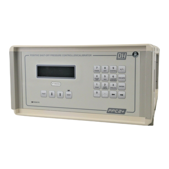
3.1.1 THE MAIN RUN SCREEN The PPC2 AF main run screen is its home display that is reached on power up and from which other functions and menus are accessed. It is the very top level of all menu structures. -
Page 24: General Operating Principles
GENERAL OPERATING PRINCIPLES 3.1.2.1 MAIN KEYPAD LAYOUT AND PROTOCOL The PPC2 AF has a 4 X 4 keypad for local operator access to direct functions, function menus and for data entry. 1. The Function/Data keys allow very commonly used functions to be... -
Page 25: Automated Pressure Control
Pressure control parameters for each control mode are automatically adjusted to optimal values for each PPC2 AF range when the control mode is selected in that range (see Section 3.2.3). If desired, control parameters can be customized by the user using the CUSTOM CONTROL function (see Section 3.2.6). - Page 26 PPC2 AF OPERATION AND MAINTENANCE MANUAL During static pressure control, the hold limit is active. If the pressure goes outside of the hold limit, a "not ready" condition will occur (see Section 3.1.2.4) and pressure will be readjusted to the target value (see Section 3.2.3 for default hold and stability limit values and Section 3.2.6 for setting the hold and stability limits).
-
Page 27: Pressure Ready/Not Ready Indication
3. OPERATION 3.1.2.4 PRESSURE READY/NOT READY INDICATION The far left character of the display provides a pressure "Ready/Not Ready" indication. This indication is intended to provide the user with a clear and objective criterion for determining when a valid pressure measurement can be made. Ready/Not Ready indications are: Pressure "ready". -
Page 28: Multiple Pressure Ranges
PPC2 AF handles all of the data and internal valving operations needed to make range changes occur transparently to the operator when the RANGE function is used to select a range. -
Page 29: Direct Function Keys
To change the currently active pressure measurement range. PRINCIPLE PPC2 AF uses a 1 000 psi (7 MPa) absolute transducer and a 50 psi (350 kPa) absolute transducer to measure reference pressures. In addition, each one of these transducers is triple ranged providing a total of six pressure ranges over the 1 000 psi pressure range of the PPC2 AF (see Section 3.1.2.5). -
Page 30: Unit
If ENTER is pressed while in the RANGE function when PPC2 AF is not vented, the display will indicate "Vent system fully to change range". Press ESCAPE or ENTER to reach the main run screen and vent using the VENT direct pressure control key. -
Page 31: Control
No reference temperature selection is necessary for the unit mmWa as the only reference temperature commonly used for mmWa is 4º C. See Section 9.3 for tables of the conversion factors used by PPC2 AF. The choice of six units available under the UNIT function can be modified from a wider selection by the user. -
Page 32: Executing Automated Pressure Control Commands
Control mode setting is range specific. A change in control mode made while in one PPC2 AF range does not affect the control mode setting in other ranges (see Section 3.2.1). - Page 33 (see Section 3.1.2.3) until automated pressure control is interrupted. See Section 6 if PPC2 AF is unable to control pressure or appears to control pressure poorly. For PPC2 AF to set pressures under atmosphere and/or to reliably set pressures under 2 psi (14 kPa) gauge other than zero gauge, a vacuum pump must be connected to the EXHAUST port (see Section 2.3.4) and PPC2 AF...
-
Page 34: Upper Limit
1050 psi a Entry field to enter desired upper limit value. Enter the desired upper limit value and PPC2 AF returns to main run screen with new upper limit value active. © 1998 DH Instruments, Inc. Page 28... -
Page 35: Seq
The sequence function is intended to facilitate the execution of a series of pressure control target values such as is commonly needed when PPC2 AF is used to run a typical calibration sequence on a device or system being tested. - Page 36 PPC2 AF OPERATION AND MAINTENANCE MANUAL When 2No is selected from the Run Current Quick Sequence menu, the set- up/edit routine is accessed. The first display is: Enter sequence FS Entry field for sequence full scale value. 100 psi a Recalls last entered value.
-
Page 37: Setting Up/Editing A File Sequence
(see Sections 3.2.5 and 3.3.3.) When initializing execution of a quick sequence, PPC2 AF checks: a) if the sequence full scale pressure exceeds the current upper limit; b) if PPC2 AF is in absolute measure mode, that the sequence does not contain negative values. - Page 38 PPC2 AF OPERATION AND MAINTENANCE MANUAL If the sequence was set up with "Next increment on timed delay", execution will proceed automatically from increment to increment after a "ready" condition has occurred at the increment and the countdown timer has expired. If the sequence was set up with "Next increment on ENTER", ENTER must be pressed to...
-
Page 39: Custom Control
Adjusting default control parameters using the CUSTOM CONTROL function may result in control parameters that the PPC2 AF is unable to meet so that a "ready" condition never occurs. This does not indicate PPC2 AF malfunction, just that the control parameters need to be relaxed or set back to default parameters. -
Page 40: Turning-Off Custom Control Parameters
TEST port. Frequently, when performing a calibration or test, the device or system under test is at a different height than the PPC2 AF’s TEST port. This difference in height, frequently called "head", can cause a significant difference between the pressure measured by the PPC2 AF at its TEST port height and the pressure actually applied to the device under test at a different height. - Page 41 PPC2 AF reference transducer in order to accurately predict the pressure actually applied at a different height. PPC2 AF can accurately calculate the "head" pressure for nitrogen, helium and air as the test gas over its working pressure range. The HEAD function allows the height difference and test gas to be specified and causes the resulting head pressure to be added to the pressure measured at the TEST port.
-
Page 42: Leak Check/Purge
However, it is likely that PPC2 AF will need to be used to test some devices or systems that contain liquid contaminants. For this case, a Self Purging Liquid Trap (SPLT) accessory supported by a PURGE function is available. -
Page 43: Leak Check/Purge Menu And Functions Flow Chart
Pressing ENTER when in the leak check screen goes to the set pressure screen (see Sections 3.2.3.1 and 3.2.8.4). In general, the maximum acceptable leak rate for optimal PPC2 AF automated pressure control operation and to assure in tolerance measurements is ± 0.02 psi (140 Pa)/second or 1.2 psi (8.3 kPa/minute) when using range 1, 2 or 3 of the Hi reference pressure transducer and 0.001... -
Page 44: Purge Function
PURGE FUNCTION For the purge function to operate, the Self Purging Liquid Trap (SPLT) must be correctly installed in the line connecting the PPC2 AF TEST port to the device or system under test. For information on SPLT installation see Section 2.3.5.1. -
Page 45: Setting Pressures For Leak Check/Purge Function
PPC2 AF TEST port. Generally, the purge process should be completed before leak checking is performed. This may not be the case when the PPC2 AF will be used to apply only ascending pressures. -
Page 46: Analog
3.2.9 ANALOG Function not implemented on PPC2 AF. SETUP MENU KEY PURPOSE The SETUP menu key accesses a menu of functions and features commonly used in setting up PPC2 AF for use. OPERATION 1ControlRef 2Resltn Press the SETUP key from the main run screen to access the SETUP menu. -
Page 47: Controlref
Connecting a vacuum pump to the PPC2 AF EXHAUST port lowers the pressure on the down side of the exhaust pressure regulator. The ControlRef function is used to inform the PPC2 AF that a vacuum has been applied to the EXHAUST port so it can take this into consideration in its control routines. OPERATION... -
Page 48: Sequence
3.2.5.3). PRINCIPLE The PPC2 AF FILE SEQUENCE function allows a sequence of automated pressure control targets in a specific range with predetermined control and operating parameters to be executed by recalling and running a sequence file. The files containing the information necessary to run a file sequence are created, stored and edited in 3Sequence of the SETUP menu. - Page 49 3. OPERATION OPERATION Sequence file setup requires the user to specify a large number of parameters in a series of data entry screens described below. For a summary of the sequence definition requirements in the order they are edited, see PRINCIPLE above. To access the Sequence file building function, press File sequence: the SETUP menu key and then 3Sequence.
- Page 50 ENTER is pressed before proceeding to the next point. If 2Timer is selected, when the sequence is executed, PPC2 AF will start a timer when a "ready" condition is reached at a pressure point. When the time expires, the sequence will proceed automatically to the next pressure point.
-
Page 51: Drivers
To control the output signals of PPC2 AF's 8 channel, 12 V external drivers. PRINCIPLE PPC2 AF external drivers are available to drive peripheral equipment in a PPC2 AF system, for example, solenoid valves. The driver electrical connections are available from a rear panel connector See Section 9.1 for driver specifications and pin-outs. -
Page 52: Presu
1PresU under the SPECIAL menu key. This allows PPC2 AF to offer a very wide selection of units while simplifying day to day operation. The typical user will customize the UNIT function key to support his/her six most commonly used units. -
Page 53: Head
Select the desired head height unit. The next display is: Select the type of gas that is being supplied to PPC2 AF. The characteristics of the gas selected will be used by PPC2 AF in calculating head pressures. 3.4.3 CONFIG PURPOSE To run an automated routine that readjusts internal pressure control characteristics. -
Page 54: Cal
These are referred to as “Term1” and “Term2”. These define the characters that mark the end of commands that are sent to the PPC2 AF as well as mark the end of replies sent back to the host computer. The PPC2 AF typically will use the “Term1”... -
Page 55: Reset
This clears out any settings that the user has set up, and should be done only to restore the PPC2 AF to a known state. PPC2 AF will restart after any type of reset is selected. -
Page 56: Level
PRINCIPLE PPC2 AF's front panel user interface provides the means to access all PPC2 AF data and functions including internal calibration data, special diagnostic functions and privileged factory functions. Certain PPC2 AF functions, if used inadvertently or by an unqualified operator may cause erroneous readings and behavior. - Page 57 SPECIAL menu, 5Diag OPERATION PPC2 AF is delivered with no active password and access to the User Level menu is open. User levels cannot be changed until a password is created and, once a password is created, entry of the password is required to access the User Level menu.
-
Page 58: Atm
The first field "nnnn" is the serial number of the PPC2 AF, followed by a second field "xx" that represents the number of times that a secondary password has been used. This second field increments each time a secondary password is used. -
Page 59: Maint
DIAG PURPOSE Allows access to advanced functions that view low level PPC2 AF data and allows editing of manufacturer calibration and operational settings that affect PPC2 AF operation. Users should not access this function without special instructions. Access to these functions is tracked by PPC2 AF to deter undesired use. - Page 60 PPC2 AF OPERATION AND MAINTENANCE MANUAL © 1998 DH Instruments, Inc. Page 54...
-
Page 61: R E M O T E O P E R At I O
Sending a command to the PPC2 AF will place it into remote mode. The remote indicator in the lower left hand corner of the PPC2 AF front panel will light when the PPC2 AF is in remote mode. It will also flicker when a command is received. -
Page 62: Com2
4.2.1.2 COM2 The PPC2 AF COM2 RS232 interface is located on the back of the unit. It can be used to allow the Host computer to communicate with another device through the PPC2 AF. This allows the user to use one Host COM port to communicate with the PPC2 AF and an additional RS-232 device. -
Page 63: Commands
(see Section 3.4.4.3). The default terminating characters are <CR><LF>. The user must wait for the PPC2 AF to reply before sending another command. All replies from the PPC2 AF are ASCII and are terminated with the designated terminating characters. -
Page 64: Error Messages
4.3.2 ERROR MESSAGES The PPC2 AF will always reply to a command. If the command is incorrect or contains invalid data, an error number will be returned in the form “ERR# n” where n is an integer number that represents a specific error. This allows for easy error trapping by the host computer. Here is... -
Page 65: Command Summary
The PPC2 AF COM2 port can be used to communicate to another RS-232 device (such as another PPC2 AF). This allows the user to use one COM port or IEEE port on the host computer to communicate with the PPC2 AF and another device. A carriage return and a line feed (<CR><LF>) are added to the string. - Page 66 “COM1=2400,E,7,1” “COM2=2400,E,7,1” Remarks: The COM1 port is used to communicate to the PPC2 AF. When the COM1 port configuration of the PPC2 is changed, the command reply will be sent at the old COM1 settings, but all subsequent communications will be accomplished at the new COM1 settings. The COM2 port can be used to communicate with additional devices.
- Page 67 The slow speed will be used for a calculated amount of time (up to 5 seconds) to create the desired change. The PPC2 AF will not attempt to control the pressure to a target, so the change in pressure will be approximate.
- Page 68 The height units. This must be “in” or “cm”. The gas type. This must be “N2”, “Air” or “He”. Remarks: The PPC2 AF can make a head correction to allow it to display the pressure at the test instead of the pressure at the PPC2 AF. Example: Command: “HEAD=10,cm,N2”...
- Page 69 The slow speed will be used for a calculated amount of time (up to 5 seconds) to create the desired change. The PPC2 AF will not attempt to control the pressure to a target, so the change in pressure will be approximate.
- Page 70 PPC2 AF OPERATION AND MAINTENANCE MANUAL MODE(=) Purpose: Read or set the control mode. Syntax: “MODE” “MODE=n” Arguments: ’0’ for static pressure control. ’1’ for dynamic pressure control. Remarks: The control mode & control mode settings are selected with the MODE command. When the control mode is set, control parameters go to default parameters for that range.
- Page 71 (R or NR). The ready status is covered in the “SR” command. The pressure measurement value and pressure units are right justified in this field. After receiving this command, the PPC2 AF will reply back with the data once a new pressure measurement cycle is complete. This can take up to 1.5 seconds.
- Page 72 The target pressure in the current pressure units. Remarks: The PPC2 AF will generate the given target pressure using just the fast speed, and will stop generating when the pressure has reached or passed the given target. The system will not attempt to hold the pressure.
- Page 73 The next available pressure rate of change in the current pressure units per second is returned. After receiving this command, the PPC2 AF will reply back with the data once a new pressure measurement cycle is complete. This can take up to 1.5 seconds.
- Page 74 Reset the user’s settings to factory defaults. Syntax: “RESET” Remarks: The PPC2 AF has user settings (units, resolution, control modes, etc.) that can be reset to factory defaults. Calibrations and sequences will not be affected. The remote “RESET” command corresponds to the local “Reset-all.” (See Section 3.4.5.2) The PPC2 AF also will restart as if the power was cycled OFF and then ON.
- Page 75 Remarks: The stability limit can be read and set as a pressure or as a percent of the range. If this command is used to set the stability limit, the PPC2 AF will then use CUSTOM control settings. Example: Command: “SS=.1”...
- Page 76 Arguments: hh:mm The time in a 12 hour format using a colon delimiter. ”am” or “pm” Remarks: The PPC2 AF has an internal real time clock. It is used for date stamping calibrations and log data. Example: Command: “TIME=12:52PM” Reply: “12:52pm”...
- Page 77 The pressure (Pa) to convert. Remarks: The PPC2 AF handles all pressure values internally in Pascal. This command allows the user to convert pressures. If a pressure is not given, 1 Pa is assumed. The reply includes the current pressure units.
- Page 78 Remarks: The PPC2 AF has an upper limit for each range of each transducer. New targets can not be greater that this value. If the pressure does exceed the upper limit, the pressure display will flash, and the unit will stop generating.
- Page 79 4. REMOTE OPERATION Purpose: Read the PPC2 AF version. Syntax: “VER” Remarks: The software version of the PPC2 AF can be read. This is useful for checking presence of the PPC2 AF and for reference purposes. Example: Command: “VER” Reply: “DH INSTRUMENTS, INC PPC2 AF Ver1.00 ”...
- Page 80 PPC2 AF OPERATION AND MAINTENANCE MANUAL © 1998 DH Instruments, Inc. Page 74...
-
Page 81: M Ai N T E N An C E , Ad J U S T M E N T S An D C Al I B R At I O
PPC2 AF operation. For rapid assistance in specific situations, see Section 6. PPC2 AF is covered by a limited 5 year warranty. Unauthorized service or repair during the warranty period is undertaken at the owner's risk and may cause damage that is not covered under warranty and/or may void the warranty (see Section 9.4). -
Page 82: Repairs
5.1.2 REPAIRS PPC2 AF is covered by a limited 5 year warranty. Unauthorized service or repair during the warranty period is undertaken at the owner's risk and may cause damage that is not covered under and/or may void the warranty (see Section 9.4). -
Page 83: Front Panel Removal And Replacement
5. MAINTENANCE, ADJUSTMENTS AND CALIBRATION 5.1.2.2 FRONT PANEL REMOVAL AND REPLACEMENT See Figures .1, .7 and .9. Remove electrical power and shut off pressure prior to executing this procedure. 1. Remove top panel (fig 7) 2. Remove front panel. 2.1. Remove ribbon cable P/N 401278 (W5) (fig 1) 2.2. -
Page 84: Rear Fitting Removal And Replacement
PPC2 AF OPERATION AND MAINTENANCE MANUAL 5.1.2.4 REAR FITTING REMOVAL AND REPLACEMENT Electric shock hazard exists when performing this procedure. Following the outlined procedure exactly is required. Disconnect power and pressure prior to any disassembly. 1. Remove adaptor fittings from rear panel fittings (fig 11) 2. -
Page 85: Barometer Board Replacement
3. Carefully pull board out from connector. Be careful not to damage pins on connector J1. 4. Install new board. 5. After re-assembly, power up the PPC2 AF. 6. The temperature coefficients must be input. 6.1. SPECIAL, DIAG, CALIB, TEMP, 6.2. -
Page 86: Supply Pressure Relief Valve Removal And Replacement
RELOADING EMBEDDED SOFTWARE INTO FLASH MEMORY 1. The PPC2 AF has flash memory, which means that when an upgrade is required or for some reason the embedded software is corrupted it can be reloaded with the help of a PC. -
Page 87: Self Purging Liquid Trap (Splt)
5. MAINTENANCE, ADJUSTMENTS AND CALIBRATION 5.1.4 SELF PURGING LIQUID TRAP (SPLT) 5.1.4.1 MAINTENANCE The maintenance of the SPLT consists of cleaning or replacing the internal coalescing filter. A dirty filter should be rinsed with a degreasing agent to remove oil and particulate matter. A filter with physical damage should be replaced. Removing and Installing the SPLT Filter See Section 5.1.5 for part number and figures referred to in the filter replacement procedure. -
Page 88: Illustrated Parts Breakdown
PPC2 AF OPERATION AND MAINTENANCE MANUAL 5.1.5 ILLUSTRATED PARTS BREAKDOWN 5.1.5.1 PARTS LISTS 5.1.5.1.1 Main Assembly See Section 5.1.5.2 Figure .1. PART NUMBER DESCRIPTION # REQUIRED 100550-Z Allen screw, M3 X 5 100969-Z Lock washer 100970-Z Nut, M3 101010-Z Allen screw, M3 X 8... - Page 89 5. MAINTENANCE, ADJUSTMENTS AND CALIBRATION 5.1.5.1.2 Pneumatic Schematic See Section 5.1.5.2 Figure .2. PART NUMBER DESCRIPTION # REQUIRED 100314 Cross connector 100318 Adaptor 100326 Tee connector 100355 2 micron filter 100817 Volume cylinder 100851 50 psia transducer 100856 1000 psia transducer 100898 Flow controller 100899...
- Page 90 PPC2 AF OPERATION AND MAINTENANCE MANUAL 5.1.5.1.3 Pneumatic Assembly See Section 5.1.5.2 Figures .3, .5 and .6. PART NUMBER DESCRIPTION # REQUIRED 100969-Z Lock washer 100971-Z Lock washer 100972-Z Hex nut 101000-Z Screw, M3 X 6 101005-Z Screw, M3 X 10...
- Page 91 5. MAINTENANCE, ADJUSTMENTS AND CALIBRATION 5.1.5.1.4 Rear Panel Assembly See Section 5.1.5.2 Figures .4, .11 and .12. PART NUMBER DESCRIPTION # REQUIRED 100632-Z Crimp terminal 100970-Z Nut, M3 100482 RS-232 socket 100589 Fuse, slo-blo 1A/250V 100985 Screw, M3 X 20 101469 Rubber grommet 102169...
- Page 92 PPC2 AF OPERATION AND MAINTENANCE MANUAL 5.1.5.1.7 SPLT Assembly See Section 5.1.5.2 Figure .10 PART NUMBER DESCRIPTION # REQUIRED 100970-Z Hex nut, M 3 101392-Z Vent tube, 1/8 in. O.D. 102088-Z Split lock washer 102464-Z Split lock washer 122461-Z Label...
-
Page 93: Figures
5. MAINTENANCE, ADJUSTMENTS AND CALIBRATION 5.1.5.2 FIGURES This section provides figures describing various subassemblies of the PPC2 AF. For associated parts lists see Section 5.1.5.1. For additional information on PPC2 AF subassemblies and their locations see Section 1.2. 5.1.5.2.1 General Assembly (Top View) - Figure 1 Page 87 ©... - Page 94 PPC2 AF OPERATION AND MAINTENANCE MANUAL 5.1.5.2.2 Pneumatic Schematic (Conceptual) - Figure 2 © 1998 DH Instruments, Inc. Page 88...
- Page 95 5. MAINTENANCE, ADJUSTMENTS AND CALIBRATION 5.1.5.2.3 Pneumatic Schematic (Top View) - Figure 3 Page 89 © 1998 DH Instruments, Inc.
- Page 96 PPC2 AF OPERATION AND MAINTENANCE MANUAL 5.1.5.2.4 Rear Panel (Front View) - Figure 4 © 1998 DH Instruments, Inc. Page 90...
- Page 97 5. MAINTENANCE, ADJUSTMENTS AND CALIBRATION 5.1.5.2.5 Pneumatic Schematic (Side View) - Figure 5 Page 91 © 1998 DH Instruments, Inc.
- Page 98 PPC2 AF OPERATION AND MAINTENANCE MANUAL 5.1.5.2.6 Rear Panel (Rear View) - Figure 6 © 1998 DH Instruments, Inc. Page 92...
- Page 99 5. MAINTENANCE, ADJUSTMENTS AND CALIBRATION 5.1.5.2.7 Bottom Panel (Top View) - Figure 7 Page 93 © 1998 DH Instruments, Inc.
- Page 100 PPC2 AF OPERATION AND MAINTENANCE MANUAL 5.1.5.2.8 Electronic Chassis (Front and Side Views) - Figure 8 © 1998 DH Instruments, Inc. Page 94...
- Page 101 5. MAINTENANCE, ADJUSTMENTS AND CALIBRATION 5.1.5.2.9 Front Panel (Front and Top Views) - Figure 9 Page 95 © 1998 DH Instruments, Inc.
- Page 102 PPC2 AF OPERATION AND MAINTENANCE MANUAL 5.1.5.2.10 SPLT (Front and Side Views) - Figure 10 © 1998 DH Instruments, Inc. Page 96...
- Page 103 5. MAINTENANCE, ADJUSTMENTS AND CALIBRATION 5.1.5.2.11 Full Rear Panel (Front View) - Figure 11 Page 97 © 1998 DH Instruments, Inc.
- Page 104 PPC2 AF OPERATION AND MAINTENANCE MANUAL 5.1.5.2.12 Power Entry Module - Figure 12 © 1998 DH Instruments, Inc. Page 98...
-
Page 105: Autozero Of Reference Transducers
To change the offset (zero) of the Lo and Hi reference pressure transducers relative to a reference value. PRINCIPLE The main component of drift over time of the PPC2 AF reference pressure transducers is zero drift or offset, independent of span. The autozero routines (AutoZ) allow the Lo and Hi reference transducers to be rezeroed relative to a reference between recalibrations. -
Page 106: Hi Ref (By Comp At Atm)
PPC2 AF OPERATION AND MAINTENANCE MANUAL OPERATION Autozero To access the autozero, press 1AutoZ under 4Internal of the SPECIAL menu. The display is: 1View 2Edit 3Run Selecting 1View allows the currently used values of PA(z)net and PA(z)tare (see Principle above) with the date that the PA(z)net was determined to be viewed. - Page 107 The autozero by comparison at atmosphere routine builds in a three minute wait to allow the reference transducers to stabilize. For best results, a one hour wait with the PPC2 AF idle and at stable temperature before running the autozero routine is recommended.
-
Page 108: Lo Ref (By Vacuum)
PPC2 AF OPERATION AND MAINTENANCE MANUAL AUTOZERO BY COMPARISON AT ATMOSPHERE ERRORS For autozero to proceed when "seeking autozero", stability of ± 0.000 15 psi (1 Pa)/second as measured by the Lo reference pressure transducer must be met. If the stability test is not met within 60 seconds, then "Autozero error: ATM, stability timeout"... - Page 109 Use the 1/4 in. Male X KF16 adaptor (Part No. 102519) to make the vacuum connection to the PPC2 AF AUTOZERO port. 2. Use a large diameter vacuum hose to connect the PPC2 AF AUTOZERO port to the vacuum source.
- Page 110 PPC2 AF OPERATION AND MAINTENANCE MANUAL New value of PA(z)net based on the PA(z)raw just measured. Value of PA(z)net currently in use. New PAzNet If the autozero routine is being run as part of Old PAzNet the calibration, the final result will be new and...
-
Page 111: Viewing And Editing Autozero Values
2No returns to the reference transducer choice without implementing edits. The PA(z) date is changed automatically to the current date using the PPC2 AF internal calendar when an edit of PA(z)net is activated or when the autozero routine is executed. -
Page 112: Adjustment Of Barometer
PPC2 AF OPERATION AND MAINTENANCE MANUAL ADJUSTMENT OF BAROMETER PURPOSE To adjust the output of the on-board barometer (see Section 1.2.6). PRINCIPLE The on-board barometer output can be adjusted using PA and PM values in the same manner as for the reference pressure transducers (see Section 5.4.1 Principle, PA/PM Coefficients) -
Page 113: Calibration Of Reference Transducers
5. MAINTENANCE, ADJUSTMENTS AND CALIBRATION CALIBRATION OF REFERENCE TRANSDUCERS 5.4.1 PRINCIPLE PPC2 AF has two reference pressure transducers that are used as the source of accurate pressure measurement for the system. Each transducer has three ranges as follows: REFERENCE TRANSDUCER RANGE (PSI) - Page 114 4Internal, 2Cal are the user PA/PM values. These values are set at the factory on a new PPC2 AF to have no effect (PA = 0, PM = 1). Thus, their change over time can be used as a measure of the evolution over time of the reference pressure transducer calibration. PA/PM values are also available under SPECIAL, 4Internal, 5Diag, 2Calib.
-
Page 115: Equipment Required
3. If the calibration will include pressures under atmospheric pressure, connect a vacuum pump to the PPC2 AF rear panel EXHAUST port (1/4 in. NPT F). There will be a constant bleed of gas through the EXHAUST port so the vacuum pump should be self-venting or disconnected when "off". -
Page 116: On-Board Reference Transducer Calibration Function
PPC2 AF OPERATION AND MAINTENANCE MANUAL 5. Connect the calibration standard output to the PPC2 AF rear panel TEST port (1/4 in. NPT F). 6. Set PPC2 AF to desired pressure unit (see Section 3.2.2) and be sure “head” correction is off (see Section 3.2.7). -
Page 117: Selection Of Reference Transducer (Hi, Lo) To Calibrate
5. MAINTENANCE, ADJUSTMENTS AND CALIBRATION 5.4.4.2 SELECTION OF REFERENCE TRANSDUCER (HI, LO) TO CALIBRATE OPERATION From main screen select Run ref sensor cal SPECIAL menu, 4Internal, 2Cal, 3Run, 1Reference. The display is: Select the reference transducer desired and press ENTER on confirmation screen or ESCAPE to change selection. -
Page 118: Running The Calibration Of A Range
Edit the pressure applied by the calibration standard and press ENTER. 5. Display of "ENTER to take point", PPC2 AF measured pressure and current calibration point number. Observe the PPC2 AF measured pressure and the pressure calibration standard. - Page 119 5. MAINTENANCE, ADJUSTMENTS AND CALIBRATION Press ENTER to proceed with the point. The next screen provides a display of current pressure as measured by the reference transducer and range being 14.50 psi a calibrated using the current PA/PM and PA(z)net instruction pressure to be applied by the calibration standard for the point:...
-
Page 120: Setting Pa(Z)Tare
ABORT calibration option. 5.4.4.5 SETTING PA(Z)TARE PRINCIPLE PA(z)tare must be set as part of the calibration process for the PPC2 AF AutoZ function to operate properly to allow "rezeroing" between calibrations (see Section 3.4.4.1, 5.4.1 Principle Setting PA(z)tare). Therefore, the determination of PA(z)tare is included as a required step in the on-board calibration function. -
Page 121: Activating Calibration Results
4. Under SPECIAL, 4Internal, 1AutoZ, 1View, read and record the current value of PA(z)net. 5. Run the calibration pressures for the range recording the pressure applied by the standard and the PPC2 AF reading at each calibration point. The data recorded is the "as received" data for this calibration. -
Page 122: Viewing Reference Transducer Calibration Information
7. Perform a linear regression to find the offset and slope that best fits the non-corrected PPC2 AF readings to the calibration standard pressures. The offset is the new value of PA, the slope is the new value of PM. -
Page 123: Diagnostic Function
5. MAINTENANCE, ADJUSTMENTS AND CALIBRATION DIAGNOSTIC FUNCTION The PPC2 AF diagnostic menu allows access to advanced functions that allow the user to view low level data and to edit manufacturer calibration settings that alter the operation of the PPC2 AF. Users should not access this menu without instruction from DH Instruments or full knowledge of these functions. - Page 124 PPC2 AF OPERATION AND MAINTENANCE MANUAL MODE = 32 Echoes the special front panel display modes DISP COUNTS or DISP PERIODS if these display modes are enabled (from the diag menu). MODE = 64 Echoes the pneumatic table to curve interpolation data.
-
Page 125: Calib
5.5.3 DISP The PPC2 AF can be set to display low level measured data to aid in troubleshooting. These following display modes will replace the normal pressure display screen that appears on power up. You can return to the normal display mode by selecting ‘norm’ in this menu, or by pressing the ESC key while viewing the display screen. -
Page 126: Relay
Internal relays are used to switch the measurements inputs from the normal measurements lines to the internal voltage references while auto calibrating. These can be manually switched to determine how the PPC2 AF is functioning. This along with the DISP modes can assist in troubleshooting. - Page 127 PPC2 AF operation. This troubleshooting guide is intended as an aid in identifying the reason for PPC2 AF behavior and determining whether the behavior is due to normal operation or an internal or external problem.
- Page 128 PPC2 AF and the by excessive overshooting and/or the test. test. undershooting, inability to "lock-on" A filter in the PPC2 AF, the SPLT or an Clean and dry or replace the filter target. accessory is dirty and causing a restriction. element (5.1.3).
- Page 129 (5.2, 2.3.4, 5.4). be recalibrated. Poor pressure control The PPC2 AF and/or the connection Purge and clean affected systems measurement. to the test system is contaminated (3.2.8, 5.1.3). with liquids. Apparent...
- Page 130 PPC2 AF OPERATION AND MAINTENANCE MANUAL © 1998 DH Instruments, Inc. Page 124...
- Page 131 Remove rubber feet caps and retract legs if extended. • Place PPC2 AF in protective plastic bag. • Place PPC2 AF front panel down in the custom shipping and storage container in which it was delivered. • Stow accessories and documents in container cut outs. •...
- Page 132 PPC2 AF OPERATION AND MAINTENANCE MANUAL © 1998 DH Instruments, Inc. Page 126...
-
Page 133: Function Keys
8. MENU TREE FUNCTION KEYS Page 127 © 1998 DH Instruments, Inc. -
Page 134: Setup Menu
PPC2 AF OPERATION AND MAINTENANCE MANUAL SETUP MENU © 1998 DH Instruments, Inc. Page 128... -
Page 135: View/Edit Sequence Menu
8. MENU TREE VIEW/EDIT SEQUENCE MENU Page 129 © 1998 DH Instruments, Inc. -
Page 136: Edit Sequence Menu
PPC2 AF OPERATION AND MAINTENANCE MANUAL EDIT SEQUENCE MENU © 1998 DH Instruments, Inc. Page 130... -
Page 137: Special Menu
8. MENU TREE SPECIAL MENU Page 131 © 1998 DH Instruments, Inc. -
Page 138: Autozero Menu
PPC2 AF OPERATION AND MAINTENANCE MANUAL AUTOZERO MENU © 1998 DH Instruments, Inc. Page 132... -
Page 139: Internal Menu
8. MENU TREE INTERNAL MENU Page 133 © 1998 DH Instruments, Inc. -
Page 140: Calibration Menu
PPC2 AF OPERATION AND MAINTENANCE MANUAL CALIBRATION MENU © 1998 DH Instruments, Inc. Page 134... -
Page 141: Run Calibration Menu
8. MENU TREE RUN CALIBRATION MENU Page 135 © 1998 DH Instruments, Inc. -
Page 142: Run Pa(Z) Tare Menu
PPC2 AF OPERATION AND MAINTENANCE MANUAL 8.10 RUN PA(z) TARE MENU © 1998 DH Instruments, Inc. Page 136... -
Page 143: Diagnostics Menu
8. MENU TREE 8.11 DIAGNOSTICS MENU Page 137 © 1998 DH Instruments, Inc. - Page 144 PPC2 AF OPERATION AND MAINTENANCE MANUAL © 1998 DH Instruments, Inc. Page 138...
-
Page 145: Drivers
120 mA 100 mA The male connector (P/N 102478) for the DRIVERS port is supplied with the PPC2 AF accessories. The following table and figure should be used as reference when building a cable to utilize the drivers port. EXTERNAL DRIVERS... -
Page 146: Splt Cable And Connections
SPLT CABLE AND CONNECTIONS In order to take advantage of the automatic purging feature of the PPC2 AF (see Section 3.2.8), the SPLT valve must be connected to the PPC2 AF’s external driver #8. This can be accomplished by soldering two 24 gauge wires of desired length to the 12 pin connector provided with the accessories. -
Page 147: Unit Conversion
UNIT CONVERSION 9.3.1 PRESSURE PPC2 AF performs all internal calculations in SI units. Numerical values input or output in other units are converted to SI immediately after entry and back to other units just before output as needed. The tables below provide the conversion coefficients used by PPC2 AF to convert numerical values expressed in SI units to corresponding values expressed in other units. -
Page 148: Warranty Statement (For Deliveries Under F33660-96-C7004)
PPC2 AF OPERATION AND MAINTENANCE MANUAL WARRANTY STATEMENT (FOR DELIVERIES UNDER F33660-96-C7004) PPC2 AFs delivered to the United States Government under contract F33660-96-C7004 are covered by a limited, 5 year worldwide warranty. The warranty start and finish dates are marked on each unit.
Need help?
Do you have a question about the PPC2 AF and is the answer not in the manual?
Questions and answers