
Related Manuals for DH Instruments FPG8601


Summary of Contents for DH Instruments FPG8601
- Page 1 FPG8601™/VLPC™ Operation and Maintenance Manual © 2007 DH Instruments, a Fluke Company...
- Page 2 The fidelity of the translation cannot be guaranteed. In case of conflict between the English version and other language versions, the English version predominates. DH Instruments, DH, DHI, PG7000 and CalTool are trademarks, registered and otherwise, of DH Instruments, a Fluke Company. Swagelok is a registered trademark of the Swagelok Company Krytox is a trademark of the Dupont de Nemours Company Document No.
-
Page 3: Table Of Contents
V L P C T H E O R Y O F O P E R A T I O N ......... . 1 9 OVERVIEW ............................19 SUPPLY AND REGULATION ........................20 FLOW CONTROL ..........................20 RANGE RESTRICTIONS ........................21 CONTROL..............................21 READY/NOT READY ..........................22 Page III © 2007 DH Instruments, a Fluke Company... - Page 4 STRIP CHARTS ............................51 6.3.5 LOGGED DATA ............................52 6.3.6 VLPC CONTROL ............................54 6.3.7 RUN DIAGNOSTICS............................56 6.3.8 DUT MANIFOLD ............................59 TOOLBARS ............................60 6.4.1 WINDOW DISPLAY TOOLBAR ........................60 6.4.2 FUNCTIONS TOOLBAR..........................61 6.4.3 VALVE CONTROL............................64 © 2007 DH Instruments, a Fluke Company Page IV...
- Page 5 DETERMINING EFFECTIVE AREA.....................117 7.8.1 SETTING UP THE SYSTEM ........................117 7.8.2 GENERATING A PRESSURE ........................118 7.8.3 ADJUSTING THE NEEDLE VALVE ......................118 7.8.4 TAKING DATA (FOR EACH PRESSURE)....................119 7.8.5 CALCULATING THE EFFECTIVE AREA ....................119 Page V © 2007 DH Instruments, a Fluke Company...
- Page 6 1 3 . G L O S S A R Y ..............1 5 3 © 2007 DH Instruments, a Fluke Company...
- Page 7 Table 17. <System Setup><Options> Options ..................71 Table 18. <Options>, <Data File> Tab Fields .................... 72 Table 19. <FPG8601 Calibration Setup> Options ..................74 Table 20. <Internal Limits> <Setup> Options .................... 75 Table 21. <Internal Limits> <Pressure> Options ..................77 Table 22.
- Page 8 Table 52. FPG Defined Pressure Calculation Variables................142 Table 53. DHI Authorized Service Providers ................... 151 Figure 1. FPG8601 Terminal Front Panel....................5 Figure 2. FPG8601 Terminal Rear Panel ....................6 Figure 3. FPG Platform Front View......................7 Figure 4. FPG Platform Back View ......................8 Figure 5.
- Page 9 Figure 61. Removing the Piston....................... 110 Figure 62. Alignment of the FPG piston in the cylinder ................113 Figure 63. FPG8601 and PG7000 Cross Float Setup ................117 Figure 64. FPG8601 Bubbling System ....................122 Figure 65. Calibration Mass Drive Assembly ................... 126 Figure 66.
- Page 10 FPG8601™/VLPC™ OPERATION AND MAINTENANCE MANUAL © 2007 DH Instruments, a Fluke Company Page X...
-
Page 11: A B O U T T H I S M A N U Al
ABOUT THIS MANUAL This manual provides the user with the information necessary to operate the FPG8601 system. It also includes a great deal of additional information provided to help you optimize system use and take full advantage of its many features and functions. - Page 12 FPG8601™/VLPC™ OPERATION AND MAINTENANCE MANUAL © 2007 DH Instruments, a Fluke Company Page XII...
-
Page 13: I N T R O D U C T I On
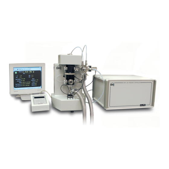
1. INTRODUCTION OVERVIEW The FPG8601 (Force-Balanced Piston Gauge), VLPC (Very Low Pressure Controller) and FPG Tools (PC Based Software) are used in conjunction to act as a high precision pressure measurement and data acquisition system. Operator interaction with the FPG/VLPC and its extensive capabilities is accomplished through the PC based software from a computer via a standard RS232 port. -
Page 14: Requirements
Lubrication Supply Port KF16 Upper Test Port KF16 Lower Test Port 1/8 in. NPT Drive In Port 1/8 in. NPT Vacuum Port Not available CE Conformance: Not used Driver Port (Ext Valve): © 2007 DH Instruments, a Fluke Company Page 2... -
Page 15: Ambient And Instrument Condition Measurements
ISO/TAG4/WG3. The result is then rounded upwards to provide conservative global figures for the typical user in typical conditions of the maximum deviation from the true value of the pressure determined by the FPG8601 and the pressure actually present at the test point. -
Page 16: Vlpc General Specifications
600 to 1000 kPa (90 to 150 psi) air Drive Air Supply: Test (Lo) 1/4 VCO Pressure Connections: Test (Hi) 1/4 VCO 1/4 VCO Vacuum 3/8 VCO Supply 1/8 NPT F Drive 1/8 NPT F © 2007 DH Instruments, a Fluke Company Page 4... -
Page 17: Fpg Platform Front And Rear Panels And Vlpc Front And Rear Panels
The front panel assembly provides a 2 x 20 vacuum fluorescent display and a 4 x 4 membrane keypad for local user interface. Display Multi-Function Keypad Figure 1. FPG8601 Terminal Front Panel Page 5 © 2007 DH Instruments, a Fluke Company... -
Page 18: Fpg Terminal Rear Panel
The rear panel assembly provides the communications connection to the FPG platform and the power connection module. Power Switch Connector for Cable to FPG (25 pin Fuse Cooling Fan Power Receptacle Figure 2. FPG8601 Terminal Rear Panel © 2007 DH Instruments, a Fluke Company Page 6... -
Page 19: Fpg Platform Front View
Vacuum Reference Port (KF-25) TEST+ (KF-16) Mounting Post Reference Mounting Post PRT Connector Vacuum Sensor Connector TEST- (KF-16) Vacuum Sensor Port Lower Mounting Post 10. Reference Level Figure 3. FPG Platform Front View Page 7 © 2007 DH Instruments, a Fluke Company... -
Page 20: Fpg Platform Back View
IEEE-488 – Not Used Drivers Option Connector - Absolute Mode – Lubrication Not Used Pressure Vacuum 10. COM3 (RS232) – Not Used Bubbler 11. FPG Terminal Port Figure 4. FPG Platform Back View © 2007 DH Instruments, a Fluke Company Page 8... -
Page 21: Vlpc Rear Panel Assembly
10. Pressure Connection – Test (Lo) Pressure Connection – Drive 11. COM1 (RS232) – To FPG Pressure Connection – Supply 12. COM2 (RS232) – Not Used Figure 5. VLPC Rear Panel Page 9 © 2007 DH Instruments, a Fluke Company... - Page 22 FPG8601™/VLPC™ OPERATION AND MAINTENANCE MANUAL © 2007 DH Instruments, a Fluke Company Page 10...
-
Page 23: F P G T H E O R Y O F O P E R A T I O
This allows the piston to center itself in the cylinder under the influence of the lubricating pressure. As a result, the piston is perfectly mobile, making no contact with the cylinder. Page 11 © 2007 DH Instruments, a Fluke Company... -
Page 24: Figure 6. Piston-Cylinder Lubricating Flow
If the port is exposed to vacuum, the FPG will measure absolute differential pressure. The measured value of the low pressure port must be applied to the FPG differential pressure to get an absolute pressure. © 2007 DH Instruments, a Fluke Company Page 12... -
Page 25: Load Cell
50 % by a bubbling system internal to the FPG. FPG Tools will display a warning message if these conditions change beyond these limits. Low humidity values cause electrostatic effects on the load cell which have adverse influence on the zero stability of the load cell. Page 13 © 2007 DH Instruments, a Fluke Company... -
Page 26: Lubrication Pressure
VACUUM REFERENCE PRESSURE The FPG8601 inherently measures differential pressure. When the lower mounting post is exposed to atmosphere, the FPG measures gauge pressure. If the lower mounting post is exposed to a vacuum, the FPG measures absolute differential pressure. -
Page 27: Simplified Formula For Calculating Differential Pressure
The simplified formula for the calculation of the differential pressure can therefore be expressed as: ΔP = K (20°C) . [ 1+ ( α + α ) . ( θ - 20 ) ] . N / A cal. eff. Page 15 © 2007 DH Instruments, a Fluke Company... -
Page 28: Reference Level
, is determined experimentally. K is determined by varying the reference pressure while holding the lubrication pressure constant. Subtracting the buoyancy changes due to the change in reference pressure (see Section 2.7.3), © 2007 DH Instruments, a Fluke Company Page 16... -
Page 29: Δn3
Since zeroing in each mode of operation is standard procedure for the FPG, this extreme situation does not occur. =mg + F θ high ΔF ΔF (δN (δN θ ΔF (δN Figure 8. FPG Forces Page 17 © 2007 DH Instruments, a Fluke Company... -
Page 30: Complete Differential Pressure Equation
In gauge measurement mode, this differential pressure is equal to the gauge pressure of the FPG. In absolute mode, the residual vacuum pressure measured by the vacuum reference sensor is applied to the calculated differential pressure to obtain the absolute pressure of the FPG. © 2007 DH Instruments, a Fluke Company Page 18... -
Page 31: L P C T H E O R Y O F O P E R A T I O
This table was generated using a D16b vacuum pump. Table 1. Nominal VLPC Ranges ABSOLUTE GAUGE (Pa) (Pa) 1 500 1 500 5 000 3 000 15 000 15 000 Page 19 © 2007 DH Instruments, a Fluke Company... -
Page 32: Supply And Regulation
After controlling to a pressure near the target, the high flow MFC is set to a constant flow while the low flow, 25 sccm, MFC performs the fine control to achieve and maintain pressure within specifications. © 2007 DH Instruments, a Fluke Company Page 20... -
Page 33: Range Restrictions
The control of both the coarse (high flow) and fine (low flow) MFCs is accomplished with PID control based on pressure readings. The FPG pressure is used for all control readings all ranges for optimum control and resolution. Page 21 © 2007 DH Instruments, a Fluke Company... -
Page 34: Ready/Not Ready
Figure 11 graphically portrays the ready criterion while the VLPC is controlling. When the VLPC is not controlling, the "Ready" condition is based on the <Stability Setting>. Figure 11. VLPC Ready Criterion © 2007 DH Instruments, a Fluke Company Page 22... -
Page 35: G E T T I N G S T A R Te
FPG and VLPC. INSTALLING FPG TOOLS Insert the installation CD included with the FPG8601 to install FPG Tools. When the CD is inserted it will automatically execute the FPG Tools installation program. However, if the auto run feature is disabled in Windows this will not occur. -
Page 36: Setting Up Fpg Tools
When the above information is properly set up, there is no need to repeat these steps unless a new setup is required. Use the [Run], [Run Monitor] menu choice to begin polling the FPG after all hardware is properly set up. © 2007 DH Instruments, a Fluke Company Page 24... -
Page 37: Basic Fpg Hardware Setup
Pressurizing the unit prematurely could introduce contaminates into the system. Attach the outlet of the external 700 kPa (100 psi) regulator, to the “lubrication pressure” port on the back of the FPG. Page 25 © 2007 DH Instruments, a Fluke Company... -
Page 38: Setting Up The Piston-Cylinder
CONNECTING THE FPG MANIFOLD AND VALVES The bypass/control manifold is connected to the right side of the FPG8601. This part is essential for automated operation of the system. Follow the steps below and refer to Figure 13 for information on connecting the manifold. -
Page 39: Figure 13. Fpg8601 Manifold Connection
When zeroed horizontally, the rotation of the sensor also affects the zero. This makes it difficult to mount remove and remount sensor without affecting the zero. Page 27 © 2007 DH Instruments, a Fluke Company... -
Page 40: Setting Up The Fpg For Operation
Install PFA vent bleed tube between the adaptor and the bulkhead on the rear of the turbopump controller. Install a KF16 x KF25 adaptor onto the turbo pump KF16 lateral port.. Attach a KF25 plastic hose from the adaptor to the roughing vacuum pump. © 2007 DH Instruments, a Fluke Company Page 28... -
Page 41: Setting Up The Vlpc
Start FPG Tools software (if not already active) and choose [Run], [Run Monitor]. Verify that the FPG is level. Use the bubble level on the top of the FPG and make adjustments with the rear feet as necessary. Page 29 © 2007 DH Instruments, a Fluke Company... -
Page 42: Connecting A Dut
Adding these valves will allow for changing DUTs while keeping the FPG in absolute mode. Connect the test port of the DUT to the KF16 valve that is attached to the test high port of the FPG. © 2007 DH Instruments, a Fluke Company Page 30... -
Page 43: Absolute Differential Mode
Attach the DUT Test (Hi) port to the upper left port on the FPG, Test (Hi). Attach the DUT Test (Lo) port to the lower left port on the FPG, Test (Lo). Page 31 © 2007 DH Instruments, a Fluke Company... -
Page 44: Connecting The Dut Manifold
DUTs should be connected to the manifold by adapting as necessary. When possible connect differential and gauge DUTs to both the high and low ports of the manifold. This ensures that the DUTs and the FPG are using the same reference pressure. © 2007 DH Instruments, a Fluke Company Page 32... -
Page 45: Setting Up The Turbo Pump
Attach a 9-pin RS232 cable to the adapter to a COM port on the PC. Attach the ION gauge cable to the ION gauge. Note that there is only one orientation that the connector will fit. Page 33 © 2007 DH Instruments, a Fluke Company... -
Page 46: Changing Lubrication Gas
Activate valve six on the valve toolbar. Allow valve six to be active for approximately 15 minutes. Deactivate valve six on the valve toolbar. Press the purge toolbar button in order to reach a stable humidity. © 2007 DH Instruments, a Fluke Company Page 34... -
Page 47: Purging The Test Port
The pressure does not have to be stable for any particular amount of time. Cycle the two previous steps at least five times. Alternatively, see Section 6.7.6 for cycling pressure in a test sequence. Page 35 © 2007 DH Instruments, a Fluke Company... - Page 48 FPG8601™/VLPC™ OPERATION AND MAINTENANCE MANUAL © 2007 DH Instruments, a Fluke Company Page 36...
-
Page 49: S Y S T E M O P E R A T I O
FPG Tools will avoid this by imposing a timeout on the zero process. If proper zero conditions are not met, the zero process is aborted and an error message is displayed on the status bar. Page 37 © 2007 DH Instruments, a Fluke Company... -
Page 50: Stability Test
Lower the internal calibration mass and again wait for stability. Average the load cell output subtracting the calibration tare obtained from Step The result is the internal calibration mass. © 2007 DH Instruments, a Fluke Company Page 38... -
Page 51: Activating New Calibration
This window contains all relevant calibration information required to determine whether or not to keep the new calibration. Select the desired option to complete the internal calibration process. Figure 14. Internal Calibration Results Window Page 39 © 2007 DH Instruments, a Fluke Company... -
Page 52: Table 4. Internal Calibration Results Options
Press cancel to close the <Internal Calibration Results> window and Cancel ignore the results of the calibration. No information related to the calibration is saved. © 2007 DH Instruments, a Fluke Company Page 40... -
Page 53: Setting A Measurement Mode
[Config], [DUT Selection] to re-activate the DUT with the changes. It is not recommended that DUTs be modified during tests. Any new DUT settings created after the test has begun are not logged into the data file. Page 41 © 2007 DH Instruments, a Fluke Company... -
Page 54: Zeroing The Dut Manifold
When the VLPC is active, the close bypass toolbar function and the [Vent] pressure option on the <VLPC Interface> window have the same function. VLPC control is aborted and all the FPG bypass valve is automatically opened. © 2007 DH Instruments, a Fluke Company Page 42... -
Page 55: Setting 0 Pressure
Prior to selecting this menu choice make sure a test sequence is defined by using the [Config], [Test Sequence Editor] option. This allows a list of target pressures to be specified along with averaging and dwell times (see Section 6.6.5). Page 43 © 2007 DH Instruments, a Fluke Company... -
Page 56: Shutting Down The Fpg
ATM is the shutdown process complete. At this point it is safe to perform maintenance operations on the FPG. To resume normal operation, press the [Shut Down] button again or re-select the current pressure measurement mode in the [Units] menu. © 2007 DH Instruments, a Fluke Company Page 44... -
Page 57: F P G T O O L
The following sections describe the features and concepts implemented in FPG Tools. Refer to Section 5 for information on how to set up FPG Tools and how to use many common features in a practical environment. Page 45 © 2007 DH Instruments, a Fluke Company... -
Page 58: Main Menu
The status bar at the bottom of the main screen provides important run time information. Always refer to this bar while the FPG pressure is being monitored. Figure 15. FPG Tools (Factory Mode) © 2007 DH Instruments, a Fluke Company Page 46... -
Page 59: Status Bar
FPG pressure is within the stability setting or hold limit, based on whether or not VLPC is actively controlling. Double click the <Rate> and/or <FPG Pressure> fields to display a strip chart of the corresponding indicator. Figure 17. <Run Display> Page 47 © 2007 DH Instruments, a Fluke Company... -
Page 60: Table 5.
The difference between the DUT and reference divided by the full scale value of the DUT %FS Error times 100. The difference between the DUT and reference divided by the reference times 100. %Reading Error © 2007 DH Instruments, a Fluke Company Page 48...Labels -
Page 61: Tare Display
The lubrication volume temperature at the time of the last system zero. This value is used Lube Temp for reference purposes only and is not applied to any calculations. The lubricating volume humidity at the time of the last tare. Page 49 © 2007 DH Instruments, a Fluke Company... -
Page 62: Plot Display
Edit plots by typing in any field. A flashing message displays to indicate that editing has begun. You must press the [New] toolbar option to create a new custom plot. © 2007 DH Instruments, a Fluke Company Page 50... -
Page 63: Strip Charts
FPG pressure rate. If the rate is oscillating about 0 for 200 samples, it is fare to say that the rate is effectively 0. Page 51 © 2007 DH Instruments, a Fluke Company... -
Page 64: Logged Data
“01010-3.dat”. To change the file name, edit the file name field of the file box that displays during initialization (see Section 9.2). Use Table 8 as a key to help determine column information found in the data file. Figure 21. <Logged Points> Display © 2007 DH Instruments, a Fluke Company Page 52... -
Page 65: Table 8.
The measurement mode used for the system zero that was in effect when the Tare Mode point was taken: g or a for gauge and absolute respectively. Ν The direct load cell output in counts. Page 53 © 2007 DH Instruments, a Fluke Company...Labels -
Page 66: Vlpc Control
However, this may leave the system in an undefined state. So make sure that a new range is set or the pressure is vented if an early abort occurs. © 2007 DH Instruments, a Fluke Company Page 54... -
Page 67: Table 9.
[Go] button to set the pressure. The value displayed in this field always represents the current target pressure when the VLPC is actively controlling pressure. A “D” in the status indicator always notes VLPC control. Page 55 © 2007 DH Instruments, a Fluke Company...Options -
Page 68: Run Diagnostics
(see Section 6.6.2.3). If the DUT is not enabled, dashes appear in this field. The direct output of the DUT formatted based on the <Leading characters to DUT Output strip> and the <Output resolution> specified in the DUT Setup. © 2007 DH Instruments, a Fluke Company Page 56... - Page 69 If this rate exceeds the rate of change limit, a re- zero warning will display on the status bar and the FPG will indicate a “Not Ready” condition. Page 57 © 2007 DH Instruments, a Fluke Company...
- Page 70 Thermal transpiration correction ratio based on the absolute pressure in the lower Lo Trans chamber of the FPG. The ratio is the effective low side DUT pressure divided by the P(DUT)/P(FPG) absolute FPG pressure in the lower mounting post. © 2007 DH Instruments, a Fluke Company Page 58...
-
Page 71: Dut Manifold
Pressure from the lower chamber of the FPG. Blue Vacuum pressure generated by the manifold Black vacuum pump. The current pressure state is undefined. This Gray typically occurs when valves are adjusted to completely isolate the gas. Page 59 © 2007 DH Instruments, a Fluke Company... -
Page 72: Toolbars
As a result, it may be necessary to scroll the main display to view the selected run screen. Figure 26. Window Display Toolbar © 2007 DH Instruments, a Fluke Company Page 60... -
Page 73: Functions Toolbar
[Take Point] prompt to enter the DUT output will occur prior to logging the point. Make sure the DUT output is entered in the configured DUT output units (see Section 6.8). Page 61 © 2007 DH Instruments, a Fluke Company... - Page 74 The lubrication pressure will build up in the mounting post and eventually reverse pressure the system. In gauge mode, [Zero Check] and [Close Bypass Valve] have the same function. This feature is intended for use in absolute mode. © 2007 DH Instruments, a Fluke Company Page 62...
- Page 75 Removes the internal calibration mass from the measuring mechanism of the load cell. The process takes approximately 10s. During this time, the FPG pressure is not valid. This function is available in advanced user level only (see Section 6.10). [Raise Internal Calibration Mass] Page 63 © 2007 DH Instruments, a Fluke Company...
-
Page 76: Valve Control
During normal system operation, FPG Tools performs all of the necessary valve operations based on the pressure measurement mode and requested operation. The ability to change valve states is provided for diagnostics purposes only. © 2007 DH Instruments, a Fluke Company Page 64... -
Page 77: Run]
Do not abort operations that take place as part of the initialization process. If the FPG is not properly initialized, pressure will not be calculated. Page 65 © 2007 DH Instruments, a Fluke Company... -
Page 78: Run Monitor]
[Run Monitor] mode and vents all system pressure. For this reason, test sequences are a good way to safely run long, multi cycle tests overnight. The steps involved with running a test sequence are described below. © 2007 DH Instruments, a Fluke Company Page 66... - Page 79 The results are logged in the data file and on the main display. Repeat Steps for each step in the test sequence. Repeat Steps for each test cycle. Page 67 © 2007 DH Instruments, a Fluke Company...
-
Page 80: Config]
User defined units may not display an appropriate amount of pressure pressure resolution (see Section 6.9.1). In this case, uncheck the option and make and resolution (check box) appropriate resolution selection. © 2007 DH Instruments, a Fluke Company Page 68... -
Page 81: System Setup]
FPG. If “N2” is selected, the FPG must be thoroughly purged of all traces of Air. Failure to properly purge when N2 is used can result in short term pressure instability and faulty pressure measurements. Page 69 © 2007 DH Instruments, a Fluke Company... -
Page 82: Options
The minimum connection tube diameter between the DUT and the DUT orifice FPG8601. This value is typically a diameter internal to the DUT. diameter Check this box to use the VLPC to control the FPG pressure. When Enable VLPC (check box) checked the <VLPC Interface>... -
Page 83: Table 17.
The Varian 150 Dry Var turbo molecular pump, model 9699163 is the only supported vacuum pump available for this option. Other Varian pumps may also work with the FPG Tools as long as the commands are 100 % compatible. Page 71 © 2007 DH Instruments, a Fluke Company...Options -
Page 84: Data File
In most cases, automatically naming the data file is desired. (check box) However, when some specific tests are executed, it can be more convenient to manually name the data files. © 2007 DH Instruments, a Fluke Company Page 72... -
Page 85: Fpg Calibration Setup]
FPG calibration information is restricted in the standard user level. The following table summarizes the features of the <Calibration Setup Screen>. Refer to the calculation section for more information on the use of these parameters. Page 73 © 2007 DH Instruments, a Fluke Company... -
Page 86: Table 19.
FPG8601™/VLPC™ OPERATION AND MAINTENANCE MANUAL Figure 32. <FPG8601 Calibration Setup> Table 19. <FPG8601 Calibration Setup> Options LABEL DESCRIPTION Maximum 50 character length field representing a summary of the FPG calibration file. Identification (text entry field) Any information that easily identifies the unit can be entered into this field. The text entered is logged in the data file.Options -
Page 87: Internal Limits]
(see Section 6.6.3). mode (check box) Check this box to apply the thermal transpiration correction to the FPG8601 Apply thermal vacuum reference sensor. By default this value is not checked because the transpiration vacuum reference sensor is not calibrated with the thermal transpiration correction to the correction active. -
Page 88: Pressure
FPG8601™/VLPC™ OPERATION AND MAINTENANCE MANUAL LABEL DESCRIPTION The minimum connection tube diameter between the vacuum reference Vacuum sensor and the FPG8601. This value is typically a diameter internal to the reference orifice vacuum reference sensor. The value is used only when thermal diameter (mm) transpiration is active for the vacuum reference sensor. -
Page 89: Temperature
<Diagnostics Display>. This forces a “Not Ready” condition. Both change in temperature and the rate of change of temperature have adverse effects on the load cell. For this reason, always use the FPG in stable laboratory conditions. Page 77 © 2007 DH Instruments, a Fluke Company... -
Page 90: Humidity
The purpose of each limit is defined in Table 23. When a humidity limit is exceeded a “H” will be listed in the <Status> category of the <Diagnostics Display>. This forces a “Not Ready” condition. © 2007 DH Instruments, a Fluke Company Page 78... -
Page 91: Mass
Internal calibrations run during automatic test sequences are not activated when any of the internal calibration limits are exceeded. Make sure the limits entered are reasonable for the test conditions. Page 79 © 2007 DH Instruments, a Fluke Company... -
Page 92: Purge
This purge is not used to exhaust all gas from the test port of the FPG and any connected DUT. To purge a DUT, set and vent several pressures prior to using the system. A test sequence can be created to purge a DUT (see Section 6.6.5). © 2007 DH Instruments, a Fluke Company Page 80... -
Page 93: Vlpc
The available ranges and the corresponding percent of range hold limits are available only after [Run], [Run Monitor] is used and the VLPC is enabled. The available ranges are dependent on the specific setup of the VLPC. Page 81 © 2007 DH Instruments, a Fluke Company... -
Page 94: Table 26.
Default Gauge hold limit specified for the selected range is set by default. The hold limit Mode Hold Limits (numeric entry field) can be changed by using the [Config], [Settings] option. © 2007 DH Instruments, a Fluke Company Page 82...Options -
Page 95: Dut Selection]
Press this button to begin polling all remote DUTs. Activate DUTs (command button) Press this button to stop polling all remote DUTs. Deactivate DUTs (command button) Aborts the DUT selection without saving changes. Cancel (command button) Page 83 © 2007 DH Instruments, a Fluke Company... -
Page 96: Test Sequence Editor
Save been made. Any test conflicts result in error messages when saving. These conflicts must be resolved before saving. (toolbar button) Creates a new Test Sequences with default information. (toolbar button) © 2007 DH Instruments, a Fluke Company Page 84... -
Page 97: Points> Table
Figure 42. Test Sequence Editor, <Test Points> Table The purpose of the <Points> table’s fields and settings as well as instructions on how to use them are provided in Table 29. Page 85 © 2007 DH Instruments, a Fluke Company... -
Page 98: Table 29. Test Sequence Editor,
The test point table can be filled in by placing the cursor in the test point field and editing the desired test point value. It can also be filled in automatically using the <Points> tab. The test point table can be cleared using <Clear> on the <Points> tab. © 2007 DH Instruments, a Fluke Company Page 86...Options -
Page 99: Points] Tab
<Points> table and new points can be inserted at any point using the <Points> table [Insert] button (see Section 6.7.2). Clear Clicking [Clear] at any time causes all entries in the test point table to clear. (action button) Page 87 © 2007 DH Instruments, a Fluke Company... -
Page 100: Sequence> Tab
<Points> table. When more than one test cycle Cycles is specified. Data from multiple cycles is included in a single Data File (see Section 9.2). (required entry field) © 2007 DH Instruments, a Fluke Company Page 88... -
Page 101: Control> Tab
<Stability Time-Out>. Page 89 © 2007 DH Instruments, a Fluke Company... -
Page 102: Cycle> Tab
Set pressure pressure cycle pressures. If a ready condition is not met by this time, the next step timeout (numeric entry field) automatically continues as though the pressure were set properly. © 2007 DH Instruments, a Fluke Company Page 90... -
Page 103: Dut Definition Editor
Saves changes to an edited DUT Definition. This button is not active when no edits have Save been made. Any DUT conflicts result in error messages when saving. These conflicts must be resolved before saving can be completed. (toolbar button) Page 91 © 2007 DH Instruments, a Fluke Company... -
Page 104: Dut Definition Selector
The DUT Definition Editor has a scroll feature allowing DUTs to be selected by scrolling. The ordering of the scrolled DUTs is determined by the last sort order in the DUT Selector. An edited DUT Definition displays in blue text in the DUT Selector. © 2007 DH Instruments, a Fluke Company Page 92... -
Page 105: Header] Tab
40 characters. The default Data File directory naming preference can (required drop use this entry to create the directory for Data Files created when this DUT is down list run (see Section 6.6.2.3). selection) Page 93 © 2007 DH Instruments, a Fluke Company... -
Page 106: Correction] Tab
Calibration date associated with the slope and offset entries. This is a text Calibration Date entry, so any date format can be accepted. The value entered is stored in (optional text entry the data file for reference. field) © 2007 DH Instruments, a Fluke Company Page 94... -
Page 107: Range] Tab
Pressure>) of the DUT in the output range unit of measure. If the output Output unit is the pressure range unit, the <Minimum Pressure> value is (required numeric copied here and cannot be changed. entry field) Page 95 © 2007 DH Instruments, a Fluke Company... -
Page 108: Tolerance] Tab
The tolerance becomes infinitely small as the reference pressure approaches zero. Instead, use a combination tolerance such as <%DUTFS OR %Reading (Greater of)>. Figure 51. DUT Definition Editor, [Tolerance] Tab © 2007 DH Instruments, a Fluke Company Page 96... -
Page 109: Read] Tab
RS232 or IEEE-488 require a remote command setup. Manual DUT data acquisition selections require a DUT output entry for each point taken. Table 39 provides information on the individual [Read] tab fields. Figure 52. DUT Definition Editor, [Read] Tab Page 97 © 2007 DH Instruments, a Fluke Company... -
Page 110: Table 39. Dut Definition Editor, [Read] Tab Fields
If a command is not properly entered or the response format is not correct, the problem should be visible in the spy window. Use the <Remote Communications> option for further troubleshooting (see Section 6.11.1)). © 2007 DH Instruments, a Fluke Company Page 98... -
Page 111: Remote Command Editor
Move the cursor to the proper position in the command string, then click the mouse button. Figure 53. <Insert Special Character> Panel Page 99 © 2007 DH Instruments, a Fluke Company... -
Page 112: Figure 54.
“dragging” the arrow, “ ”, next to it. Each DUT or data acquisition device has it’s own unique set of remote interface commands. Refer to the DUT manual for details on remote commands. © 2007 DH Instruments, a Fluke Company Page 100...Panel -
Page 113: Figure 55.
RS232. The <COM Port> selection should represent the physical connection of the device and an RS232 port on the host computer or the currently configured reference device. Figure 56. <RS232 Settings> Panel Page 101 © 2007 DH Instruments, a Fluke Company...Panel -
Page 114: Units]
Pa. Finally, select a display resolution appropriate for the new unit. User defined units require a unique name to prevent confusion with other pressure units. Figure 57. <User Defined Unit Setup> © 2007 DH Instruments, a Fluke Company Page 102... -
Page 115: Absolute Mode], [Gauge Mode]
This step can be included in the automated range change sequence (see Section 6.6.2.1). Allow at least 30 minutes before continuing to the next step. Zero the FPG, then run an internal calibration. Page 103 © 2007 DH Instruments, a Fluke Company... -
Page 116: Absolute Mode]
If you do not wish to use a password, just press [Enter]. After a password is entered, it must be used to change user levels. If you forget your password, contact DH Instruments technical service for assistance. © 2007 DH Instruments, a Fluke Company Page 104... -
Page 117: Tools]
All displays, data files and numeric entries will use the selected decimal separator. Including remote DUTs that may or may not directly output with the current decimal separator. FPG Tools automatically displays the final DUT pressure with the correct decimal separator. Page 105 © 2007 DH Instruments, a Fluke Company... - Page 118 FPG8601™/VLPC™ OPERATION AND MAINTENANCE MANUAL © 2007 DH Instruments, a Fluke Company Page 106...
-
Page 119: Overview
There is no scheduled piston-cylinder cleaning interval, cleaning should only be undertaking when necessary. Maintenance cleaning may be necessary if the FPG8601 has been back pressured or if the piston is not supplied with lubricating gas pressure for extended periods. Back pressuring occurs when the pressure in the piston-cylinder mounting post exceeds the pressure in the lubricating volume. -
Page 120: Figure 59. Fpg8601 Piston Assembly In Mounting Post
FPG8601™/VLPC™ OPERATION AND MAINTENANCE MANUAL 1. Upper mounting post Gimbal ring 2. Piston retaining nut 5. Cylinder 3. Indexing block with 3 mm indexing pin 6. Piston Figure 59. FPG8601 Piston Assembly in Mounting Post © 2007 DH Instruments, a Fluke Company Page 108... -
Page 121: Removing The Piston-Cylinder From The Mounting Post
If this happens, contaminants can be introduced into the low-pressure chamber of the mounting post. Fully remove the lower mounting post and set it on a clean surface. Page 109 © 2007 DH Instruments, a Fluke Company... -
Page 122: Figure 60. Removing The Mounting Post
Body oils and acids can permanently etch the surfaces. Remove one of the piston retaining nuts. Figure 61. Removing the Piston With one hand supporting the piston to maintain its current position, slowly remove the remaining piston retaining nut. © 2007 DH Instruments, a Fluke Company Page 110... -
Page 123: Removing The Piston From The Cylinder
FPG piston insertion tool. Slide the cup containing the cylinder up and off the spindle. Remove the cylinder from the cup. Page 111 © 2007 DH Instruments, a Fluke Company... -
Page 124: Cleaning The Piston And Cylinder
To clean the piston-cylinder, it must first be removed from the FPG8601 and the piston taken out of the cylinder (see Sections 7.2, 7.3). Once the piston and cylinder is removed and separated, proceed as follows: Place two clean lint-free towels on a flat surface. -
Page 125: Putting The Piston Into The Cylinder
Slide the cup and cylinder all the way down the insertion tool spindle. Page 113 © 2007 DH Instruments, a Fluke Company... -
Page 126: Installing The Piston-Cylinder In The Mounting Post
Insert one piston retaining pin and thread it half way in. Insert the remaining piston retaining pin so that it is tight. Tighten the first piston retaining pin. © 2007 DH Instruments, a Fluke Company Page 114... -
Page 127: Restoring Piston-Cylinder Lubrication And Mobility
Observe the value of <N> on the FPG Tools Run Display Screen (see Section 6.3.2). This is the output of the FPG8601 load cell. Alternate the four methods until the output of the load cell is consistently stable ± 1 or 2 counts. Then install the lower mounting post and start the FPG8601 by pressing the [On] button on the FPG Tools Run Display Screen. - Page 128 Lighly “strum” the bearing to cause a small amount of movement and let the ring return naturally. The movement is very limited. Do not force it. © 2007 DH Instruments, a Fluke Company Page 116...
-
Page 129: Determining Effective Area
Without the metering valve, the lubrication flow will increase the FPG pressure relative to the piston gauge and cause the piston gauge piston to continually rise. Figure 63. FPG8601 and PG7000 Cross Float Setup Page 117 © 2007 DH Instruments, a Fluke Company... -
Page 130: Generating A Pressure
Verify that opening and closing the isolation valve does not effect the piston gauge drop rate. If the isolation valve state affects the drop rate of the piston gauge piston, the needle valve must be readjusted. In this case, repeat step 1. © 2007 DH Instruments, a Fluke Company Page 118... -
Page 131: Taking Data (For Each Pressure)
FPG calibration setup (see Section 6.6.3). Calculated slope determined from the linear regression. When the FPG pressure is in kPa and the pressure difference is in mPa, the value has the unit (mPa/kPa). Page 119 © 2007 DH Instruments, a Fluke Company... -
Page 132: Table 42. Sample Effective Area Spread Sheet
- 24 - 16 15.0 14.98127 14.98091 - 360 - 24 - 16 -25.085 M (ppm) 17.400 B (mPa) For reference 9.80516E-04 Ae used in test [m 9.80491E-04 Determined Ae [m © 2007 DH Instruments, a Fluke Company Page 120... -
Page 133: Overview
The vacuum reference sensor is a high accuracy low range device that is used by the FPG8601 to define an absolute reference pressure, from the natural differential pressure determined from the load cell, piston and cylinder (see Section 2.5). -
Page 134: Zeroing The Vacuum Sensor
Table 44. Vacuum Reference Zeroing Equipment List EQUIPMENT FPG Tools Software Various KF fittings Varian turbo pump model V70LP and controller or equivalent Roughing pump (Optional) Ion Gauge © 2007 DH Instruments, a Fluke Company Page 122... -
Page 135: Set - Up
After the 10 hour warm-up time is complete, turn on the roughing pump connected to the turbo pump. Make sure the turbo pump exhaust valve is closed. Allow the vacuum pump to run for a couple minutes. Page 123 © 2007 DH Instruments, a Fluke Company... - Page 136 If the value is positive, enter a negative number and visa versa. Use the [Accept] button to store the changes prior to leaving the <System Setup> window. Switch to user level (see Section 6.10). © 2007 DH Instruments, a Fluke Company Page 124...
-
Page 137: Calibrating The Internal Calibration Mass
Set the load cell cover aside on a flat and clean surface. Remove the o-ring between the load cell cover and load cell plate. Page 125 © 2007 DH Instruments, a Fluke Company... -
Page 138: Remove The Calibration Mass And Drive
The equations below describe this process. ρ ρ 0.014544 1.0487E 1.8969E ⎛ ⎞ ρ ⎜ ⎜ ⎟ ⎟ ρ ⎝ ⎠ mass © 2007 DH Instruments, a Fluke Company Page 126... -
Page 139: Put The Mass Back Into The Drive Assembly
Calibration Setup> form, enter the new true mass value in the <Calibration Mass> field. Click the [Save] button to activate the change. Run a new internal calibration prior to running any calibrations with the FPG. Page 127 © 2007 DH Instruments, a Fluke Company... -
Page 140: Mounting Post Prt Calibration
Figure 66. PRT Calibration Cable Adaptor Table 47. PRT Calibration Cable Connections FROM SIGNAL P1-1 I Source P1-2 Upper (,1) + P1-3 Upper (,1) - P1-4 I Ret P1-5 Lower (,2) + P1-6 Lower (,2) - © 2007 DH Instruments, a Fluke Company Page 128... -
Page 141: Determine The Ro Value
FPG will be used. The resistance of the PRT is adjusted based on the temperature reference value as described in the equation below. The FPG8601 PRTs use a slope of 0.3896 instead of ITS90 coefficients. -
Page 142: Reattach The Prts To The Fpg
PRT. PREPARING FOR STORAGE / SHIPMENT This section describes the steps and recommended sequence for shutting the down the FPG8601 system and packaging it for long term storage and / or shipment. 8.6.1 FPG8601 Return instrument to Gauge Mode. -
Page 143: 3-Dut Manifold
Disconnect vacuum pump from underside of the manifold and cover the connection with a protective cap. Lower DUT jack stands. Remove the corrugated metal tubes cover the connections with protective caps. Wrap the 3-DUT manifold in plastic before placing the storage case. Page 131 © 2007 DH Instruments, a Fluke Company... - Page 144 FPG8601™/VLPC™ OPERATION AND MAINTENANCE MANUAL © 2007 DH Instruments, a Fluke Company Page 132...
-
Page 145: Overview
(see Section 5.3.2). All data displayed on the <Internal Calibration Results> form is stored in this file. The first line of the file is a list of column headings. Each subsequent line contains data specific to an internal calibration. Page 133 © 2007 DH Instruments, a Fluke Company... -
Page 146: System Zero Log File
This file can track down when the outage occurred and how long it lasted. If the "FPG.err" file becomes large, simply delete the file after verifying that there are no pending issues that this file may be used to resolve. © 2007 DH Instruments, a Fluke Company Page 134... -
Page 147: Overview
FPG is fully vented Clean the FPG piston (see Section 7). and the pressure is still unstable. FPG is in purge mode. Normal behavior. Bubbles keep coming through the Page 135 © 2007 DH Instruments, a Fluke Company... - Page 148 COM port on the host PC. The port on the host PC must be specified An communications error occurs using the [Config], [System Setup], interfacing with the FPG8601 and FPG The COM port setup in FPG Tools is <Interface> option. The default port settings Tools.
-
Page 149: Internal Valves
Manually adjusting the states of individual valves requires a thorough understanding of the FPG pneumatic circuit. Actuating valves in the wrong sequence can cause damage and/or contamination to the FPG. Figure 67. FPG Internal Valve Configuration Page 137 © 2007 DH Instruments, a Fluke Company... -
Page 150: Table 50. Internal Valve Descriptions
Controls the vacuum reference sensor isolation valve on the front of the lower mounting post. FPG Tools actuates this valve to allow the vacuum reference sensor to measure the pressure in the lower mounting post. The pneumatic driver for this valve is on the FPG base. © 2007 DH Instruments, a Fluke Company Page 138... -
Page 151: Unit Conversions
@ 60°F 4.018429 E-03 inch of water inHg @ 0°C 2.953 E-04 inch of mercury 1.019716 E-05 kilogram force per centimeter square User User defined coefficient User Page 139 © 2007 DH Instruments, a Fluke Company... -
Page 152: Fpg8601 Pressure Calculations
⎡ ⎤ ⎛ ⎞ ⎛ ⎞ ⎜ ⎟ ⎜ ⎟ ⋅ ⋅ ⎢ − ⎥ ⋅ δ ⎜ ⎟ ⎜ ⎟ ⋅ ⋅ ⎢ ⎥ ⎝ ⎠ ⎝ ⎠ ⎣ ⎦ © 2007 DH Instruments, a Fluke Company Page 140... -
Page 153: Thermal Transpiration Correction
⎥ ⎣ ⎦ ⎡ ⎤ ⎢ ⎥ ⎢ ⎥ ⋅ ⎢ ⎥ ⎢ ⎥ ⎣ ⎦ − ˆ − ˆ − ˆ − 1. KF Poulter, et al, Vacuum, 1983, 33:311-316 Page 141 © 2007 DH Instruments, a Fluke Company... -
Page 154: Table 52. Fpg Defined Pressure Calculation Variables
Reference pressure at tare ref,0 Reference pressure with transpiration correction ref,T N•m/mol•K Universal gas constant (= 8314.411) Temperature of DUT (i.e., head temperature) Temperature of reference pressure gas © 2007 DH Instruments, a Fluke Company Page 142... - Page 155 Density of high pressure test gas (upper mounting post) ρ kg/m Density of lubrication gas ρ kg/m Density of internal mass ρ kg/m Density of reference pressure test gas (lower mounting post) Page 143 © 2007 DH Instruments, a Fluke Company...
-
Page 156: Sample Calculations
This spreadsheet includes pressure calculations in gauge, absolute and absolute differential measurement modes. Use the spreadsheet to better understand the FPG pressure calculations and to recalculate the FPG pressure under different circumstances. 11.3.5.1 GAUGE PRESSURE © 2007 DH Instruments, a Fluke Company Page 144... -
Page 157: Absolute Pressure
11. APPENDIX 11.3.5.2 ABSOLUTE PRESSURE Page 145 © 2007 DH Instruments, a Fluke Company... -
Page 158: Absolute Differential Pressure
FPG8601™/VLPC™ OPERATION AND MAINTENANCE MANUAL 11.3.5.3 ABSOLUTE DIFFERENTIAL PRESSURE © 2007 DH Instruments, a Fluke Company Page 146... -
Page 159: Internal Calibration (Kcal)
Safety Requirements for Electrical Equipment for Measurement, Control, and Laboratory Use The EMC and Safety tests listed above were performed by Intertek Testing Services NA, Inc. The results of these tests are contained in reports on file at DH Instruments, a Fluke Company and are available upon request. -
Page 160: System Level Grounding
FPG8601™/VLPC™ OPERATION AND MAINTENANCE MANUAL 11.5.1 SYSTEM LEVEL GROUNDING © 2007 DH Instruments, a Fluke Company Page 148... -
Page 161: Fpg Ground Diagram
11. APPENDIX 11.5.2 FPG GROUND DIAGRAM Page 149 © 2007 DH Instruments, a Fluke Company... -
Page 162: Vlpc Power Diagram
FPG8601™/VLPC™ OPERATION AND MAINTENANCE MANUAL 11.5.3 VLPC POWER DIAGRAM © 2007 DH Instruments, a Fluke Company Page 150... -
Page 163: Table 53. Dhi Authorized Service Providers
12. WARRANTY STATEMENT Except to the extent limited or otherwise provided herein, DH Instruments, a Fluke Company (DHI) warrants for one year from purchase, each new product sold by it or one of its authorized distributors, only against defects in workmanship and/or materials under normal service and use. Products which have been changed or altered in any manner from their original design, or which are improperly or defectively installed, serviced or used are not covered by this warranty. - Page 164 FPG8601™/VLPC™ OPERATION AND MAINTENANCE MANUAL © 2007 DH Instruments, a Fluke Company Page 152...
-
Page 165: 3 . G L O S S Ar
The device being tested or calibrated. DUT (Device Under Test) Fluid head correction to the pressure defined by the FPG8601 to predict the pressure at the level DUT Head of the DUT which may be different from the FPG8601 reference level. - Page 166 FPG8601™/VLPC™ OPERATION AND MAINTENANCE MANUAL © 2007 DH Instruments, a Fluke Company Page 154...
Need help?
Do you have a question about the FPG8601 and is the answer not in the manual?
Questions and answers