
Related Manuals for DH Instruments GPC1-10000


Summary of Contents for DH Instruments GPC1-10000
- Page 1 GPC1-10000/GPC1-16000™ Gas Pressure Controller Operation and Maintenance Manual © 2007 DH Instruments, a Fluke Company...
- Page 2 © 2007 DH Instruments, a Fluke Company All rights reserved. Information in this document is subject to change without notice. No part of this document may be reproduced or transmitted in any form or by any means, electronic or mechanical, for any purpose, without the express written permission of DH Instruments, a Fluke Company 4765 East Beautiful Lane Phoenix AZ 85044-5318 USA.
-
Page 3: Table Of Contents
ADJUST INLET PRESSURE ........................12 2.4.3 APPLY PDVV DRIVE PRESSURE ......................12 2.4.4 CHECK OPERATION OF COMPONENTS....................13 2.4.5 PRECAUTIONS TO TAKE BEFORE GENERATING PRESSURE/SAFETY CONSIDERATIONS.....14 STORAGE AND SHIPPING ........................14 SPECIAL CONSIDERATIONS FOR HYDROCARBON FREE OPERATION ........15 Page I © 2007 DH Instruments, a Fluke Company... - Page 4 GPC1-10000 / GPC1-16000™ OPERATION AND MAINTENANCE MANUAL O P E R A T I O N ..............1 7 OPERATING PRINCIPLE ........................17...
- Page 5 Figure 6. System Schematic ........................18 Figure 7. Front Panel View ........................19 Figure 8. PDVV Plunger Position Indicator....................21 Figure 9. Drain Port Location ........................24 Figure 10. PDVV Drive Air Filter ........................ 25 Page III © 2007 DH Instruments, a Fluke Company...
- Page 6 GPC1-10000 / GPC1-16000™ OPERATION AND MAINTENANCE MANUAL © 2007 DH Instruments, a Fluke Company Page IV...
-
Page 7: A B O U T T H I S M A N U Al
WONDER ABOUT ALL THE GREAT FEATURES YOU MIGHT BE MISSING, GET INTO THE MANUAL! Manual Conventions (Caution) is used throughout the manual to identify user warnings and cautions. (NOTE) is used throughout the manual to identify operating and applications advice and additional explanations. Page V © 2007 DH Instruments, a Fluke Company... - Page 8 GPC1-10000 / GPC1-16000™ OPERATION AND MAINTENANCE MANUAL © 2007 DH Instruments, a Fluke Company Page VI...
-
Page 9: I N T R O D U C T I On
GPC1-16000 is capable of both setting and precisely adjusting pressure from atmosphere to 110 MPa (16 000 psi). GPC1-10000 covers the range from atmosphere to 70 MPa (10 000 psi). GPC1 combines the versatility, speed and reliability of direct operator control with the convenience and effort-free operation of automation. -
Page 10: Specifications
21.5 cm H x 30 cm W x 53.5 cm D (8.5 in. x 11.8 in. x 21.1 in.) GPC1-16000: 0 to 110 MPa (16 000 psi) Pressure Range GPC1-10000: 0 to 70 MPa (10 000 psi) Maximum adjustable pressure depends on pneumatic power supply (see above). -
Page 11: Instrument Layout
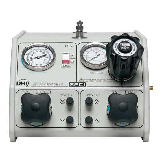
PDVV increase fast and slow buttons PDVV decrease fast and slow buttons Test outlet valve knob Figure 1. Front Panel View 1.3.2 OVERALL DIMENSIONS Figure 2. Front and Side Views with Dimensions Page 3 © 2007 DH Instruments, a Fluke Company... -
Page 12: System Schematic
GPC1-10000 / GPC1-16000™ OPERATION AND MAINTENANCE MANUAL 1.3.3 SYSTEM SCHEMATIC Figure 3. System Schematic 1. High pressure gas SUPPLY connection 11. Sump filter (not shown) (left lateral) 12. TEST INLET valve 2. Supply accumulator 13. Fast and slow PDVV increase valves 3. -
Page 13: I N S T A L L A T I On
Verify the items received against the parts list in Table 1. Table 1. GPC1 Parts List DESCRIPTION PART # GPC1-16000 or GCP1-16000 (Hydrocarbon free version) 401800 or 401801 GPC1-10000 or GPC1-10000 (Hydrocarbon free version) 402200 or 402201 ACCESSORIES INCLUDING: Mat, Top Surface Protection 123481 Operation and Maintenance Manual 550126 Wrench, Open End, 5/8 in. -
Page 14: Site Requirements
GPC1-10000 / GPC1-16000™ OPERATION AND MAINTENANCE MANUAL SITE REQUIREMENTS The GPC1 system installation is affected by the other components that make up the system in which GPC1 is being used. Generally, a pressure measuring reference such as a piston gauge or transfer standard is included. -
Page 15: Initial Setup
For 50 MPa (7 500 psi): Supply 600 kPa (87 psi) For 70 MPa (10 000 psi): Supply 700 kPa (100 psi) For 110 MPa (16 000 psi): Supply 850 kPa (120 psi) Page 7 © 2007 DH Instruments, a Fluke Company... -
Page 16: Make High Pressure Gas Supply Connection
This kit includes the high pressure hardware necessary to connect GPC1 to a DHI RPM or PG7202 and operate at pressure up to 110 MPa (16 000 psi) (limited to 70 MPa (10 000 psi) with GPC1-10000). See Figure 4 for the recommended layout and to identify the parts used from the interconnection kit. -
Page 17: Other High Pneumatic Pressure Interconnections
110 MPa (16 000 psi) (limited to 70 MPa (10 000 psi) with GPC1-10000). The 1/8 in. (3 mm ) diameter tube with DH500 tips can be very useful when a small amount of flexibility is needed to make a connection. -
Page 18: Recommendations For Test Port Connection, Use And Dut Cleanliness Considerations
GPC1-10000 / GPC1-16000™ OPERATION AND MAINTENANCE MANUAL When planning system interconnections, consider that the time required to generate and stabilize a pressure is a direct function of the test volume and the mechanical stability of the test tubing and vessels. Always minimize volume to the extent possible and use thick walled, high pressure tubing and vessels. -
Page 19: Figure 5. Clean Test Port, Sump And Drain Port
2. TEST INLET SET regulator 6. DRAIN port 3. TEST1 port (top, rear) 7. TEST INLET valve 4. TEST2 port (left lateral) 8. TEST OUTLET valve Figure 5. Clean TEST Port, Sump and Drain Port Page 11 © 2007 DH Instruments, a Fluke Company... -
Page 20: Power Up And Verification
GPC1-10000 / GPC1-16000™ OPERATION AND MAINTENANCE MANUAL POWER UP AND VERIFICATION 2.4.1 APPLY THE HIGH PRESSURE SUPPLY This section assumes that the GPC1 system has already been set up, including pressure interconnection (see Section 2.3.1). Proceed as follows (numerical references refer to Section 3.1, Figure 6): Fully back off the TEST INLET SET regulator (5). -
Page 21: Check Operation Of Components
When leak checking is complete, slowly open the OUTLET valve to reduce pressure and vent to atmosphere. Page 13 © 2007 DH Instruments, a Fluke Company... -
Page 22: Precautions To Take Before Generating Pressure/Safety Considerations
GPC1-10000 / GPC1-16000™ OPERATION AND MAINTENANCE MANUAL 2.4.5 PRECAUTIONS TO TAKE BEFORE GENERATING PRESSURE/SAFETY CONSIDERATIONS Highly pressurized gas can be extremely hazardous if proper procedures are not followed or incorrect hardware is used. Before using GPC1 to set and adjust pressure, consider the following: •... -
Page 23: Special Considerations For Hydrocarbon Free Operation
If using a gas booster to supply the high pressure, the gas booster must be a hydrocarbon free version. If using a PG7202 piston gauge, the PG7202 must be a hydrocarbon free version and used with Krytox® lubricated piston-cylinder modules. Page 15 © 2007 DH Instruments, a Fluke Company... - Page 24 GPC1-10000 / GPC1-16000™ OPERATION AND MAINTENANCE MANUAL © 2007 DH Instruments, a Fluke Company Page 16...
-
Page 25: O P E R A T I O
GPC1 is a self-contained system designed to set and adjust gas pressure into static pressure test and calibration systems. GPC1-16000 operates from atmosphere (zero gauge) to 110 MPa (16 000 psi). GPC1-10000 operates to 70 MPa (10 000 psi). GPC1 combines the capability to execute large pressure changes very quickly with very fine pressure adjustment. -
Page 26: Figure 6. System Schematic
GPC1-10000 / GPC1-16000™ OPERATION AND MAINTENANCE MANUAL Figure 6. System Schematic 1. High pressure gas SUPPLY connection 11. Sump filter (not shown) (left lateral) 12. TEST INLET valve 2. Supply accumulator 13. Fast and slow PDVV increase (plus) valves 3. Supply filter (not shown) 14. -
Page 27: Operational Functions
INLET valve is opened, this pressure can be generated rapidly in the system connected to GPC1. Use caution in setting the TEST INLET regulator pressure and always check the setting and adjust if necessary before using the TEST INLET valve (see Section 2.4.2). Page 19 © 2007 DH Instruments, a Fluke Company... -
Page 28: Rough Pressure Generation/Control, Inlet And Outlet Valve Operation
GPC1-10000 / GPC1-16000™ OPERATION AND MAINTENANCE MANUAL 3.2.2 ROUGH PRESSURE GENERATION/CONTROL, INLET AND OUTLET VALVE OPERATION Numerical references in this section refer to Section 3.2, Figure 7. For information on the GPC1 operating principle, see Section 3.1. The INLET valve (5) and OUTLET valve (8) are used to execute large pressure changes in the test system and for rough pressure control. -
Page 29: Connecting A Device Under Test (Dut)
Do not break the TEST1 port connection under pressure as, if unclean gas is present in GPC1, this could cause it to flow to the TEST1 port. Page 21 © 2007 DH Instruments, a Fluke Company... -
Page 30: Purging Liquids From The Dut/System Under Test
GPC1-10000 / GPC1-16000™ OPERATION AND MAINTENANCE MANUAL 3.2.5 PURGING LIQUIDS FROM THE DUT/SYSTEM UNDER TEST GPC1 includes a sump to collect liquids that may return from the device or system under test to which it is connected. However, the amount of liquid that the sump can handle without liquids entering other GPC1 internal circuitry is limited. -
Page 31: M A I N T E N A N C E A N D A D J U S T M E N T
GPC1 is covered by a limited 1 year warranty (see Section 6.2). Unauthorized service or repair during the warranty period is undertaken at the owner's risk and may cause damage that is NOT covered under product warranty and/or may void the product warranty. Page 23 © 2007 DH Instruments, a Fluke Company... -
Page 32: Purging The Sump (Drain)
GPC1-10000 / GPC1-16000™ OPERATION AND MAINTENANCE MANUAL PURGING THE SUMP (DRAIN) The GPC1 sump (see Figure 6, Ref 10) is designed to collect liquids that may be returned from the pressure supply or system/device under test so that they do not contaminate the rest of the system. The sump has a limited volume should be drained regularly as part of normal operation. -
Page 33: Figure 10. Pdvv Drive Air Filter
Once the filter body cap is removed, the sintered filter element can be removed. 1/4 in. (6.35 mm) PFA tube PDVV DRIVE filter downstream connection Filter body PDVV DRIVE filter upstream connection Figure 10. PDVV Drive Air Filter Page 25 © 2007 DH Instruments, a Fluke Company... - Page 34 GPC1-10000 / GPC1-16000™ OPERATION AND MAINTENANCE MANUAL © 2007 DH Instruments, a Fluke Company Page 26...
-
Page 35: T R O U B L E S H O O T I N
TEST INLET SET regulator is set INLET gauge. Adjust INLET regulator, increase pressure. too low and/or external pressure increase supply pressure if necessary. 2.3.2, supply to low. 3.2.1, Table 2 Page 27 © 2007 DH Instruments, a Fluke Company... - Page 36 GPC1-10000 / GPC1-16000™ OPERATION AND MAINTENANCE MANUAL © 2007 DH Instruments, a Fluke Company Page 28...
-
Page 37: A P P E N D I C E
Used to release pressure and for rough pressure adjustment. The high gas pressure in GPC1 PDVV, at its TEST connections and in the system to Test Pressure which GPC1 is connected. Page 29 © 2007 DH Instruments, a Fluke Company... -
Page 38: Warranty Statement
GPC1-10000 / GPC1-16000™ OPERATION AND MAINTENANCE MANUAL WARRANTY STATEMENT Except to the extent limited or otherwise provided herein, DH Instruments, a Fluke Company (DHI) warrants for one year from purchase, each new product sold by it or one of its authorized distributors, only against defects in workmanship and/or materials under normal service and use.
Need help?
Do you have a question about the GPC1-10000 and is the answer not in the manual?
Questions and answers