Table of Contents
Advertisement
Quick Links
Advertisement
Table of Contents

Related Manuals for AUSTRALIAN MONITOR AM1200


Summary of Contents for AUSTRALIAN MONITOR AM1200
- Page 1 AM1200 O p e r a t i o n M a n u a l...
- Page 2 IMPORTANT! Please read carefully. This operation manual contains important information regarding safety precautions, installation, performance, operation and maintenance of your AM1200 power amplifier. You should familiarize yourself with the contents of this manual before operating your amplifier. Safety Precautions and Labelling...
- Page 3 Features: - 4, 3 or 2 channel operation. - Input signal strapping (loop through) connectors. Custom designed, 3RU heavy duty alloy chassis. - Active balanced inputs. - Modular construction. - 21 Position detented attenuators. - Symmetrical layout - even weight distribution. - Massive heat-sink / heat-exchangers.
-
Page 4: Table Of Contents
Contents Page Introduction Controls, Connectors and Indicators 2.1 Front Panel 2.2 Rear Panel Installation Operation Bridge Mode Two Ohm or Not Two Ohm Maintenance Warranty Specification List of Illustrations Page Figure 1. Block Diagram Figure 2. Front Panel Layout Figure 3. Rear Panel Layout Figure 4. -
Page 5: Introduction
The AM1200 amplifiers are 3 unit (5.25") tall, 19" wide speakers, at high duty cycles for extended periods. Figure 1 Amplifier Block Diagram... -
Page 6: Controls, Connectors And Indicators
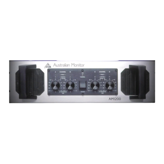
6 Controls & Connectors 2. Controls, Connectors & Indicators Figure 2 Front Panel Layout... -
Page 7: Front Panel
2 ohms or less. The circuit has two stages of operation: Figure 1 shows the panel layout of the AM1200. The functions of the controls and indicators are as follows: 1. It will provide indication (e.g. gross overload) but does not affect the input signal (a faint flash). -
Page 8: Figure 3 Rear Panel Layout
8 Controls & Connectors Figure 3 Rear Panel Layout... -
Page 9: Rear Panel
12.D.C. Rail Fuses 9. SPEAKON Output Connector Your AM1200 amplifier is fitted with 8 Amp fuses per The NEUTRIK (NL4MP) 4 way SPEAKON connector rail - per channel, as overload protection for the is provided as the main speaker output termination. -
Page 10: Figure 4. Case Dimensions
10 Installation Figure 4 Dimensions... -
Page 11: Installation
When you first receive your amplifier it may not have a mains plug attached. You must ensure that an Each pair of channels in your AM1200 amplifier is appropriate plug is used and corresponds with the cooled by an axial fan which draws cool air from the amplifier’s current (ampere) requirements and meets... -
Page 12: Figure 5. "Speakon" Connector Wiring
12 Installation NOTE: In-line XLR connectors often have a termination connector for speaker output, use only the mating lug that connects directly to the chassis of the connector. NEUTRIK NL4FC in-line connector. This connector is Do not link this lug to pin 1 at the amplifier’s input as designed so that both channels can be sourced from it will defeat the amplifier’s input grounding scheme. -
Page 13: Operation
-15dB position, otherwise clipping of the Very Important input circuitry and its resultant distortion will occur Due to the high power ability of the AM1200 you need before full output power is achieved. to be aware that certain precautions need to be... - Page 14 14 Operation Each channel of your amplifier has a nominal produces a voltage drop due to the wire’s resistance. balanced input impedance of 18k Ohms (@1kHz) This voltage difference between the amp earth and and should not present a difficult load for any signal source equipment earth appears to the amplifier's source.
-
Page 15: Bridge Mode
70 volt & 100 volt distribution lines. In BRIDGE will be on the pin marked 2+. mode, The AM1200 can produce over 70 volts with line impedances greater than 8 ohms and over 80 volts with NOTE: You should check after market manufactured line impedances greater than 16 ohms. -
Page 16: Two Ohm Or Not Two Ohm
Loudspeakers operating within an enclosure are specified with a nominal impedance. This nominal Your AM1200 amplifier is able to drive 2 ohm loads or impedance is only a rough guide to the load it presents to an amplifier. -
Page 17: Maintenance
Due to the openness of the air path through your of the unit. These rail fuses are in series with the AM1200 amplifier, very little dust should settle positive and negative output supply to each amplifier within the amplifier. The unit has been designed so channel and provide overall protection for the output stage. -
Page 18: Warranty
-SERIES 2 YEAR WARRANTY REGISTRATION IMPORTANT Please complete this card and return it immediately after unpacking the product. This card is to be sent DIRECTLY to Australian Monitor. NOTE! Warranty is effective ONLY upon receipt of this card. COMPANY NAME... -
Page 19: Specification 19
General The AM1200 will deliver or exceed - 200 watts RMS into an 8 ohm load - 300 watts RMS into a 4 ohm load - 600 watts RMS bridged into an 8 ohm load *for a single, pair, or all four channels being driven continuously (with less than 0.05% IMD and THD from 1 watt to rated power) from 20Hz to 20kHz. - Page 20 www.australianmonitor.com.au Distributed by: Audio Telex Communications Pty Ltd ACN 001345482 www.audiotelex.com.au International Enquiries Ph: 612 9647 1411, Fax: 612 9748 2537, E-mail: ho@audiotelex.com.au Sydney Ph: (02) 9647 1411, Fax: (02) 9648 3698, E-mail: nsw@audiotelex.com.au Melbourne Ph: (03) 9890 7477, Fax: (03) 9890 7977, E-mail: vic@audiotelex.com.au Brisbane Ph: (07) 3852 1312, Fax: (07) 3252 1237, E-mail: qld@audiotelex.com.au Adelaide...
Need help?
Do you have a question about the AM1200 and is the answer not in the manual?
Questions and answers