Advertisement
INSTALLATION ADJUSTMENT SERVICE
IMPORTANT! Provide serial number when ordering parts!!
INSTALLATION AND FIELD ADJUSTMENTS ARE THE
RESPONSIBILITY OF INSTALLER. READ ALL
1. Leonard Proton Valves are factory pre-assembled and
tested and include digital mixing valve and controls
which function as a system to meet both high and low
demand for tempered water.
2. System should be installed at a location where it can
easily be cleaned, adjusted or repaired.
3. System supplies must be connected as shown (Hot-left,
Cold-right). Exercise caution when soldering.
Model PNV-150-LF-LCV – 1.25" Inlets, 1.5" Outlet (less check valves)
Check valves are recommended to prevent cross-flow on "LCV" models
Model PNV-200-LF-LCV – 2" Inlets and 2"Outlet (less check valves)
Model PNV-300-LF-LCV – 3" Inlets and 3"Outlet (less check valves)
Check valves are recommended to prevent cross-flow on "LCV" models
Maximum Operating Pressure 200PSI (13.8 BAR), valve only
Hot Water Temperature Range: 120º - 180ºF (49º - 82ºC)
Cold Water Temperature Range: 39º - 80ºF (4º - 27ºC)
Temperature Adjustment Range: 65º - 180ºF (18º - 82ºC)
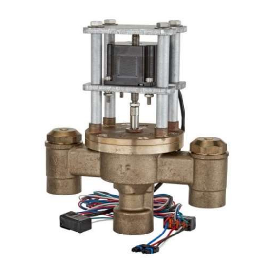
PROTON VALVE
INSTRUCTIONS PRIOR TO INSTALLATION
Model PNV-100-LF – 3/4" Inlets, 1" Outlet
Model PNV-125-LF – 1" Inlets and 1.25"Outlet
Model PNV-150-LF – 1.25" Inlets, 1.5" Outlet
Model PNV-200-LF – 2" Inlets and 2"Outlet
Model PNV-300-LF – 3" Inlets and 3"Outlet
1360 Elmwood Avenue, Cranston, RI 02910 USA
Phone: 401.461.1200 Fax: 401.941.5310
Email:
info@leonardvalve.com
Web Site: http://www.leonardvalve.com
4. Flush pipes thoroughly after system has been
connected.
5. This assembly MUST be piped according to
LEONARD'S REQUIRED PIPING METHOD W.
6. Refer to pages 2-3 of this bulletin for correct Setup
Instructions.
7. Suitable for indoor use only
Bulletin PNV-1
June 2024
WARNING: This product can
expose
you
to
chemicals
including lead, which is known
to the State of California to
cause
cancer.
For
more
information,
go
to
www.P65Warnings.Ca.gov
!
1
Advertisement
Table of Contents

Related Manuals for Leonard PNV-300-LF-LCV


Summarization of Contents
Installation and Field Adjustments
General Installation Instructions
Key instructions for valve installation, including system connections and flushing.
Proton Valve Models and Specifications
Lists available Proton valve models and their specifications like pressure and temperature ranges.
Proton 1.0 Setup Instructions
Control Box and Initial Power-Up
Details the Proton control box features, user interface, and initial valve sweep process.
Electrical and Piping Connections
Outlines essential electrical and piping connection guidelines for safe and proper valve operation.
Proton 1.0 Installation Steps
Component Connection and Pressurization
Step-by-step guide for connecting valve components, pressurizing, and powering up the system.
Valve Alignment Verification
Explains how to verify correct valve alignment after initial power-up using the LED screen.
Proton 1.0 Temperature Scale Configuration
Changing Between Fahrenheit and Celsius
Instructions on how to switch the temperature display between Fahrenheit and Celsius using a jumper.
Proton 1.0 User Interface and Operation
Home Screen and Temperature Adjustment
Details the Home Screen display and how to adjust the set point temperature using the keypad.
Navigating the Standard Menu
Explains how to navigate the standard menu options using the control panel buttons.
Proton 1.0 System Information and Calibration
Viewing Power Supply and Firmware
How to check the input power supply voltage and the current firmware revision.
RTD Probe Calibration Procedure
Guide for calibrating the RTD probe to ensure accurate temperature readings.
Proton 1.0 Calibration and Home Screen Details
Full Valve Sweep Count Calibration
How to enter and save the initial Full Valve Sweep value for calibration purposes.
Return to Home Screen Navigation
Explanation of returning to the Home Screen after calibration and menu navigation.
Proton 1.0 Error Code Troubleshooting
Error Code 1: Check Probe
Diagnosing and resolving "Check Probe" errors related to the RTD temperature probe.
Error Code 2: Valve Service Required
Addressing "Valve Service Required" errors indicating internal mechanical issues.
Error Code 3: T3 High or Low
Understanding and resolving T3 High/Low errors related to outlet temperature deviations.
Proton 2.0, 2.5 & 3.0 Setup Instructions
Control Box and Initial Sweep
Details the control box, user interface, and initial valve sweep for newer Proton models.
Connection Points and Wiring
Outlines connection points for various components like probes, relays, and power supply.
Proton 2.0, 2.5 & 3.0 Installation Steps
Component Connection and Pressurization
Step-by-step guide for connecting components, pressurizing, and powering up the system for new models.
Connector Pinouts and Alarm Functions
Details connector pin assignments and the functions of various alarm codes.
Proton 2.0, 2.5 & 3.0 User Interface
Home Screen and Temperature Adjustment
Explains the Home Screen display and process for adjusting the set point temperature.
Navigating Standard Menu Options
Guide to navigating through the standard menu options and features of the controller.
Proton 2.0, 2.5 & 3.0 System Status and Mode
Viewing Power Supply and Firmware Version
How to check the input power supply voltage and the current firmware version.
Checking Controller Mode
Verifying the controller is operating in the correct "Proton" mode.
Proton 2.0, 2.5 & 3.0 Optional Menu Screens
Viewing Inlet Water Temperatures
Displays for monitoring cold and hot water inlet temperatures to the mixing valve.
Viewing Return Water Temperature
Shows the system return water temperature to the mixing valve.
Proton 2.0, 2.5 & 3.0 Probe Calibration
Outlet Probe Calibration
Calibrating the outlet probe to match downstream temperature measurements.
Hot Water Probe Calibration
Calibrating the hot water inlet probe for accurate temperature readings.
Proton 2.0, 2.5 & 3.0 Additional Probe Calibration
Cold Water Probe Calibration
Calibrating the cold water inlet probe to match temperature readings.
Return Water Probe Calibration
Calibrating the return water probe for accurate system temperature monitoring.
Proton 2.0, 2.5 & 3.0 Advanced Calibration
Full Valve Sweep Count Calibration
Entering and saving the initial Full Valve Sweep value for calibration.
Temperature Scale and Bacnet Configuration
Setting the temperature scale (F/C) and configuring Bacnet capability.
Exiting Proton Calibration
Returning to Home Screen
Instructions on how to exit calibration mode and return to the main Home Screen.
Proton 2.0, 2.5 & 3.0 Error Code Troubleshooting
Error Code 1: Check Probe
Diagnosing and resolving "Check Probe" errors for new models.
Error Code 2: Valve Service Required
Addressing "Valve Service Required" errors indicating mechanical issues.
Error Code 3: T3 High or Low
Understanding and resolving T3 High/Low errors related to outlet temperature.
Proton 2.0, 2.5 & 3.0 Disinfection Mode
Entering Disinfection Mode
Steps to enter the disinfection mode for sanitizing plumbing systems.
Setting Minimum Disinfection Temperature
Configuring the minimum temperature required for the disinfection cycle to run.
Proton 2.0, 2.5 & 3.0 Disinfection Mode Setup
Setting Maximum Disinfection Temperature
Setting the maximum temperature for the disinfection cycle.
Configuring Warmup and Duration
Setting warmup time and disinfection cycle duration.
Proton 2.0, 2.5 & 3.0 Disinfection Cycle Confirmation
Confirming Disinfection Parameters
Reviewing and confirming the programmed parameters before initiating the cycle.
Disinfection Cycle Status and Errors
Monitoring the disinfection cycle status and potential errors like "temp too low".
Proton 2.0, 2.5 & 3.0 Disinfection Cycle Execution
Stabilization and Duration Countdown
Details the stabilization period and countdown during the disinfection cycle.
Cycle Completion and Cooldown
Explains how the disinfection cycle ends and the system enters cooldown mode.
Sensor Troubleshooting and Replacement
Identifying Sensor Errors
Troubleshooting "Check Probe" errors indicating sensor disconnection or damage.
Replacing RTD Temperature Probes
Step-by-step instructions for replacing defective RTD temperature probes.
Installing and Replacing Temperature Probes
Temperature Probe Installation Procedure
Detailed instructions for installing temperature probes using compression fittings.
Required Piping Method W
Piping Diagram and Notes
Visual guide and important notes for the required piping method W.
Maintenance and Servicing Recommendations
Recommendations for regular maintenance and servicing of the mixing valves.
BMS Connection Procedure
Connecting to Building Management System
Instructions for connecting the Proton controller to a Building Management System (BMS).
Configuring Network Parameters
Steps to select protocol, set network parameters, and save configurations.
BMS Communication Object Lists
BACnet Object List Details
List of objects and their properties for BACnet communication.
MODBUS Object List Details
List of objects and their properties for MODBUS communication.
Wi-Fi Connection Procedure
Connecting Proton 3.0 to Wi-Fi Network
Step-by-step guide to connect the Proton 3.0 controller to a Wi-Fi network.
Configuring and Accessing Dashboard
Setting up parameters, uploading certificates, and accessing the online dashboard.
PNV100 and PNV125 Parts and Kits
Kit Types and Inclusions
Overview of available kit types (O-Ring, Repair, Check) and their included components.
Exploded View and Item Numbers
Exploded view of the valve components with corresponding item numbers and part quantities.
PNV150 and PNV200 Parts and Kits
Kit Types and Inclusions
Details the available kit types and their included parts for PNV150/PNV200.
Exploded View and Item Numbers
Illustrated breakdown of valve components with item numbers and quantities for PNV150/PNV200.
Check Valve Rebuild Kits
PNV-150-LF 1-1/4" Check Valve Parts
Lists parts and rebuild kit inclusions for the PNV-150-LF 1-1/4" check valve.
PNV-200-LF 2" Check Valve Parts
Lists parts and rebuild kit inclusions for the PNV-200-LF 2" check valve.
PNV300 Parts and Kits
Kit Types and Inclusions
Details available kit types and their included components for the PNV300 model.
Exploded View and Item Numbers
Illustrated breakdown of PNV300 valve components with item numbers and quantities.
Distinguishing Controller Types
Controller Models 1.0 vs 2.0, 2.5, 3.0
Visual and tabular comparison to differentiate between Proton 1.0 and 2.0/2.5/3.0 controllers.
Valve Performance and Limitations
Minimum Flow and Temperature Maintenance
Explains temperature maintenance capabilities at low flow rates and required recirculation.
Capacity Range and Limitations
Highlights system limitations and the importance of observing flow capacity charts.
Need help?
Do you have a question about the PNV-300-LF-LCV and is the answer not in the manual?
Questions and answers