Advertisement
Quick Links
INSTALLATION ADJUSTMENT SERVICE
IMPORTANT! Provide serial number when ordering parts!!
INSTALLATION AND FIELD ADJUSTMENTS ARE THE
RESPONSIBILITY OF INSTALLER. READ ALL
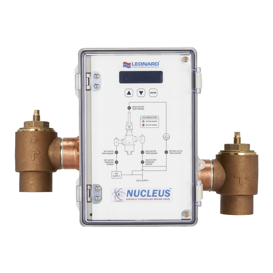
1. Leonard Nucleus Valves are factory pre-assembled and
tested and include digital mixing valve and controls
which function as a system to meet both high and low
demand for tempered water.
2. System should be installed at a location where it can
easily be cleaned, adjusted or repaired.
3. System supplies must be connected as shown (Hot-left,
Cold-right). Exercise caution when soldering.
Maximum Operating Pressure 125PSI (8.6 BAR) for Hot and Cold Water.
Hot Water Temperature Range: 120º - 180ºF (49º - 82ºC)
Cold Water Temperature Range: 39º - 80ºF (4º - 27ºC)
Temperature Adjustment Range: 65º - 180ºF (18º - 82ºC)
NUCLEUS VALVE
INSTALLATION
HOT INLET
MIXED OUTLET
INSTRUCTIONS PRIOR TO INSTALLATION
Model NV-150-LF – 1¼" Inlets, 1½" Outlet
Model NV-200-LF – 2" Inlets and Outlet
Model NV-300-LF – 3" Inlets and Outlet
1360 Elmwood Avenue, Cranston, RI 02910 USA
Phone: 401.461.1200 Fax: 401.941.5310
Email:
info@leonardvalve.com
Web Site: http://www.leonardvalve.com
COLD INLET
WARNING: This product can expose you to
chemicals including lead, which is known to the State
of California to cause cancer. For more information, go
to
www.P65Warnings.Ca.gov
4. Flush pipes thoroughly after system has been
connected.
5. This
assembly MUST be piped according
LEONARD'S REQUIRED PIPING METHOD W.
6. Refer to pages 2-4 of this bulletin for correct Setup
Instructions.
Bulletin NUC-1
March 2022
to
1
Advertisement

Related Manuals for Leonard NUCLEUS NV-200-LF


Summary of Contents for Leonard NUCLEUS NV-200-LF
- Page 1 INSTALLATION AND FIELD ADJUSTMENTS ARE THE RESPONSIBILITY OF INSTALLER. READ ALL INSTRUCTIONS PRIOR TO INSTALLATION 1. Leonard Nucleus Valves are factory pre-assembled and 4. Flush pipes thoroughly after system has been tested and include digital mixing valve and controls connected.
-
Page 2: Setup Instructions
ISOLATION VALVE WARNING The Leonard Nucleus Digital Mixing Valve is an electronically controlled device utilizing DC circuitry. The Green Wire Earth Ground Connector MUST be properly grounded to a nearby suitable earth ground prior to connecting the Outlet RTD Probe, Motor Wiring Harness and the Main Unit Power Supply. -
Page 3: Installation Instructions
INSTALLATION INSTRUCTIONS 1. The Nucleus Unit MUST be piped according to a Leonard Required Piping Method W (see page 31). 2. Mount valve body outlet facing down and plumb inlet and outlet connections. DO NOT introduce water to the valve until completion of these instructions. - Page 4 Nucleus Digitally Controlled Mixing Valve User Interface The Nucleus Digitally Controlled Mixing Valve consists of an electronics box that is simplistic in design and has a user interface that is intuitive. The Overlay pictured above is a graphical representation of a typical plumbing system where a Digital Thermostatic Mixing Valve provides mixed hot water to the plumbing system.
-
Page 5: Home Screen
User Screens Home Screen: Current outlet temperature and Set point temperature Home Screen: After initial “Full Sweep” the digital display indicates current measured temperature on the mixed outlet of the valve (T3) and shows set point temperature on the line below. Note: A large negative value displayed at the Cur temp line indicates the sensor is damaged or not properly wired to the main control board. - Page 6 Menu Screen 2: Inlet Cold Water Temperature Pressing ▼ 2 times displays Cold temp: XXX F or C This screen displays actual cold water inlet supply temperature as measured at RTD (T2) if the Nucleus is so equipped with the optional inlet temperature sensors. Note: A large negative value displayed at the Cold temp line is an indication that there is no sensor installed to the main control board, the wiring to the main board is improper or the sensor is damaged.
- Page 7 Pressing ▼ 4 times displays Hot psi: XX.XX This is a measurement of the inlet hot water supply pressure (PSI) available to the mixing valve if the Nucleus is so equipped with the optional Pressure Sensor (P1). Note: A large negative value displayed at the Hot psi line is an indication that there is no sensor installed to the main control board, the wiring to the main board is improper or the sensor is damaged.
- Page 8 Note: If the Nucleus control box is equipped with a Daughter Board the following will show: This Menu Screen will be followed by the additional screens associated with the optional equipment that may or may not be incorporated into the Nucleus configuration. The following additional equipment may be on board: 4 additional Temperature Probes (RTD’s) T5, T6, T7, T8, 2 Flow Meters (F1 &...
- Page 9 Menu Screen 8: Optional Temperature Probe 6 (T6) Pressing ▼ 8X displays Temp 6: XXX F or C This indicates and displays actual temperature as measured on RTD (T6) if the Nucleus is so equipped with the optional temperature sensors. Note: A large negative value displayed at the Temp 6 line is an indication that there is no sensor installed to the main control board, the wiring to the main board is improper or the sensor is damaged.
- Page 10 Menu Screen 11: Optional Flow Sensor (F1) Pressing ▼ 11 times displays Flow 1: XXX This indicates and displays actual flow in (GPM) on Flow channel 1 for the optional Daughter Board. See Page 28 for wiring setup. Note: A large negative value displayed at the Flow 1 line is an indication that there is no sensor installed to the main control board, the wiring to the main board is improper or the sensor is damaged.
-
Page 11: Main Power Supply
Pressing ▼ 15X displays BMS Connected: N or Y In order for this to be 'Y', or YES, the control box needs the following conditions: The Leonard supplied ProtoCessor needs to be installed on the main Printed Circuit Board. This screen confirms that the protocol converter is communicating with the main PCB. - Page 12 Menu Screen 15: Building Management System Module Pressing ▼ 16 times displays FW Rev: X.X.X.X This screen shows the current version of Firmware loaded into the Nucleus processor. It may be used for reference and troubleshooting. Home Screen: Current outlet temperature and Set point temperature Pressing ▼...
- Page 13 Nucleus Digitally Controlled Mixing Valve Commissioning The commissioning menu on the Nucleus Digitally Controlled Mixing Valve is entered by pressing a sequence of keys on the keypad as a “protected” step as this requires the end-user to be aware of potential changes to the programming and the subsequent associated potential risk to users downstream of the device.
- Page 14 Commissioning Menu Screen 2: Temperature Scale Pressing ▼ 1 time displays Min temp Initial Screen in commissioning menu requests the scale of temperature measurement in Fahrenheit (F) or Celsius (C) Commissioning Menu Screen 3: Minimum System Temperature Pressing ▼ 2 times displays Min temp This is minimum temperature as measured on the primary outlet temperature sensor of the Nucleus Mixing Valve RTD (T3).
- Page 15 Commissioning Menu Screen 5: Error Time to Make Live Pressing ▼ 4 times displays Err TTML This indicates the TIME TO MAKE LIVE, which is an elapsed time in seconds as to when an actual error will be identified by the processor (e.g. low inlet supply pressure) and then subsequently recognized as a true error and displayed on the LCD screen.
- Page 16 Commissioning Menu Screen 8: Shuttle Full Sweep Pressing ▼ 7 times displays Commissioning Full sweep: N or Y This feature allows the user to manually ‘sweep’ the shuttle inside the main valve body from full hot to full cold position in order to verify mechanical integrity of the device, and verify that the valve is traveling the entire range of its expected travel or operating range.
- Page 17 Commissioning Menu Screen 10: Maximum Alarm Temperature for Temperature Sensor #5 Pressing ▼ 9 times displays Commissioning Temp 5 max: 185F This is the maximum temperature for RTD probe T5. Any temperature above this setting at T5 will trigger an error message. Default setting is 185˚F Commissioning Menu Screen 11: Minimum Alarm Temperature for Temperature Sensor #6 Pressing ▼...
- Page 18 Commissioning Menu Screen 13: Minimum Alarm Temperature for Temperature Sensor #7 Pressing ▼12 times displays Commissioning Temp 7 min: 32F This is the minimum temperature for RTD probe T7. Any temperature below this setting at T7 will trigger an error message. Default setting is 32˚F Commissioning Menu Screen 14: Maximum Alarm Temperature for Temperature Sensor #7 Pressing ▼...
-
Page 19: Thermal Disinfection
Commissioning Menu Screen 16: Maximum Alarm Temperature for Temperature Sensor #8 Pressing ▼ 15 times displays Commissioning Temp 8 max: 185F This is the maximum temperature for RTD probe T8. Any temperature above this setting at T8 will trigger an error message. Default setting is 185˚F ----------------------------------------------------------------------------------------------------------------------------------------------------------------------------------------- THERMAL DISINFECTION WARNING: The Nucleus Digitally Controlled Mixing Valve is equipped with the ability to program the... - Page 20 Before a disinfection cycle is initiated, the MIN and MAX settings MUST be changed to accommodate higher outlet temperatures. MIN setting should be set to the minimum desired disinfection temperature. MAX setting should be changed to the maximum desired disinfection temperature. After the first minute of disinfection, an error will be triggered if the outlet temperature is below the MIN or above the MAX settings, which will automatically end the cycle.
- Page 21 Once the disinfection cycle has ended, the valve will enter COOL DOWN mode and go back to its last position before disinfection was engaged. The screen will display the current outlet temperature. Cool down can be a lengthy process, as water will need time to cool via radiation. Provisions should be made to manually “dump”...
- Page 22 Commissioning Menu Screen 18: Manually Adjust Motor Pressing ▼ 17 times displays Commissioning Adj motor: N or Y SEVERE BURNS, SEVERE INJURY AND/OR EVEN DEATH MAY OCCUR IF SAFETY PROVISIONS ARE NOT IN PLACE WHEN MANUALLY ADJUSTING THE MOTOR POSITION! THIS ACTION SHOULD ONLY BE PERFORMED BY AUTHORIZED PERSONNEL This feature allows the user to manually move the motor to ensure that it is mechanically connected, mechanically sound, and moving properly with no mechanical binding.
- Page 23 Commissioning Menu Screen 20: Save Commissioned Values Pressing ▼ 19 times displays Commissioning Save: N or Y This feature will save by selecting ‘Y’ all commissioning menu settings if they have been altered. Selecting ‘N’ will not save any altered values and will not commission the controller if it has not been commissioned.
- Page 24 Nucleus Digitally Controlled Mixing Valve Error Codes Error codes are displayed on LCD screen once TTML has been exceeded. Errors must be manually cleared by pressing ENTER when TTL time has elapsed and the error condition has not been corrected. Error codes below are listed in order of importance to valve and system performance.
- Page 25 Ensure sensor and harness are properly Inlet hot water pressure sensor connected. Check wired connection to disconnected from harness or controller, ERP1OS controller and confirm proper configuration not properly installed to controller or (see page 28 for wiring diagram). Replace broken probe if broken Ensure sensor and harness are properly...
- Page 26 Temperature at probe (7) above configured ERT7+ Investigate cause maximum temperature Temperature at probe (7) below configured ERT7- Investigate cause minimum temperature Ignore error if no probe is present. Check Optional temperature probe (8) wired connection to controller and confirm ERT8OS disconnected from controller, not properly proper configuration (see page 28 for wiring...
- Page 27 ALARM RELAY DETAIL SECTION DETAIL MASTER PCB ALARM NC COM NO ALARM RELAY LOCATION ON MASTER PCB The Nucleus Electrical Control Board has one Alarm Relay Circuit. See Master PCB location above. The alarm relay is rated for the following: 30 Volts DC, 2A Max, 60W, NO Only, SELV, LPS or Class 2 The alarm relay is only activated based on input from the primary RTD temperature probe on the mixed water outlet (T3).
- Page 28 BOARD WIRING DIAGRAMS WIRING KEY MOTOR WIRING PRESSURE RTD TEMPERATURE FLOW FROM MOTOR TO FROM BOARD TO SENSOR PROBE METER CONNECTOR CONNECTOR M-1 = RED M-1 = RED P#-1 = RED = +5V T#-1 = WHITE = NEG M-2 = RED / WHITE M-2 = WHITE F#-1 = BLACK = SIG P#-2 = BLUE = SIG...
- Page 29 SENSOR TROUBLESHOOTING AND REPLACEMENT When a sensor is disconnected or no longer in proper working condition, an error message is displayed on the controller (see complete error list starting on page 24). If this sensor is on the master printed circuit board (PCB) then the error will be accompanied by a flashing red LED light on the overlay.
- Page 30 INSTALLING AND REPLACING TEMPERATURE PROBES The RTD temperature probes used with Nucleus assemblies are simple to install. On the valve body the temperature probe is connected to the valve with a ¼” MNPT x ⅛”compression fitting. The remaining temperature probes, if present, are installed into the pipe using a ½”...
- Page 31 FOR MULTIPLE TEMPERED LOOPS, A BALANCING VALVE AND CHECK VALVE MUST BE INSTALLED ON EACH LOOP AFTER TEMPERED FIXTURES Leonard Nucleus Digital Mixing Valves are simple NOTE: Leonard Nucleus Digital Mixing Valves in design and may be easily cleaned, adjusted must be regularly maintained to provide best and repaired.
- Page 32 #10 cover assembly includes • Cover, plates • Motor • Stem • O-rings • Shuttle All fully assembled See picture #4 on page 34 ITEM # DESCRIPTION QTY. NV150 / NV200 NV300 O-RING, COVER KIT 1/NV, KIT R/NV KIT 1/NV3, KIT R/NV3 O-RING, COVER KIT 1/NV, KIT R/NV KIT 1/NV3, KIT R/NV3...
- Page 33 NV-150-LF, 1-1/4” CHECKS NV-200-LF, 2” CHECKS ITEM # DESCRIPTION QTY. PART # / KIT # LOWER STEM & PACKING KIT 2/200/C SCREEN KIT 2/200/C SPRING,CHECK KIT 2/200/C O-RING, COVER KIT 2/200/C O'RING, UPPER STEM KIT 2/200/C STEM, UPPER CHECK 4727 CHECK BONNET 4723 REMEMBER! THIS IS A CONTROL DEVICE WHICH MUST...
-
Page 34: Servicing Instructions
SERVICING INSTRUCTIONS WARNING: Before servicing Nucleus series valves, be sure to shut down inlet hot, cold and outlet water supplies and power down the Nucleus control box. Failure to do so could result in damage to the control box and could cause injury and/or death to the service technician 1. - Page 35 8. Reassemble the cover assembly. Place in a safe Remove Sleeve Assembly from Body location. Disassemble Sleeve 9. Remove sleeve assembly from valve body and clean all surfaces. Replace O-ring on bottom of part if 9B. Model NV-300-LF: Using 5/32” Allen key, remove the damaged or worn.
- Page 36 MINIMUM PRESSURE DROP FLOW (GPM) (l/min) 0.70 0.97 1.4 3.4 BAR 0.25* 100 115 122 136 140 158 165 GPM 0.95* 189 273 326 379 435 462 515 530 598 625 l/min MINIMUM PRESSURE DROP FLOW (GPM) (l/min) 0.97 1.4 3.4 BAR 0.25* 115 130 147 165...
- Page 37 Leonard’s instructions, for a period of one year from the date of shipment. During this period, Leonard will at its option repair or replace any product, or part thereof, which shall be returned, freight prepaid, to the Leonard factory and determined by Leonard to be defective in materials or workmanship.
- Page 38 COMMISSIONED PARAMETERS RECORD KEEPER Use the table below to record all of the commissioned parameters from the Nucleus. These parameters can be referenced later using this form. PARAMETER VALUE 5V Motor Scale Min Temp Max Temp Err TTML Err TTL Aux2 Flow Temp 5 min Temp 5 max...
Need help?
Do you have a question about the NUCLEUS NV-200-LF and is the answer not in the manual?
Questions and answers