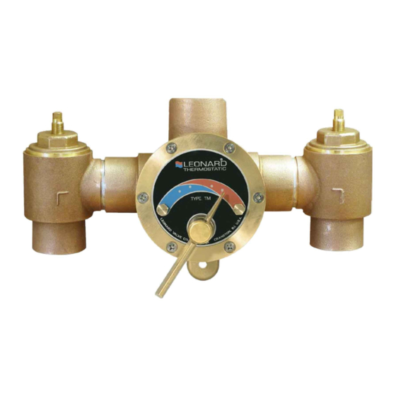
Table of Contents
Advertisement
Quick Links
INSTALLATION ADJUSTMENT SERVICE
IMPORTANT! Provide valve serial numbers (stamped on cover of valve) when ordering parts!
1.
Valve should be installed where it can easily be cleaned,
adjusted or repaired.
2.
The inlets are clearly marked on the valve body casting.
Connect the hot water into the inlet marked "HOT" and cold
water into the inlet marked "COLD". These are not to be
confused with the "C-H" markings on the front cover.
3.
Union angle checkstops furnished must be installed on both
supply lines as shown above.
Maximum Operating Pressure 125PSI (860 KPA) for Hot and Cold Water.
Required when hot water in the 140°F (60°C) range is to be circulated to a
master mixer or individual thermostatic mixing valves which are a
substantial distance from the hot water source. It is used primarily in a
building with several risers, with tempered water in each riser controlled
by a separate master mixer. NOTE: The engineer must determine
maximum distance which can be run, i.e. maximum allowable time for hot
water to reach user with one showerhead operating, based upon code
requirements and/or good practice.
WARNING! This piping will not perform effectively if the valve is oversized (see chart p4). Minimum flow must be no
less than as shown on page 4. For estimating hot water demand, consult Leonard Caspak® Plus Sizing Program.
TM-200, (OLD STYLE)
TM-300, T-225, T-250, T-300)
INSTALLATION
1360 Elmwood Avenue, Cranston, RI 02910 USA
Phone: 401.461.1200 Fax: 401.941.5310
Email:
info@leonardvalve.com
Web Site: http://www.leonardvalve.com
4.
A shutoff valve must be installed on the outlet pipe. Type
TM valves do not have a built-in shutoff.
5.
Use solder or pipe cement sparingly. Supply pipes should be
flushed before the valve is connected. Flush outlet pipe and
valve as soon as it is connected.
6.
Refer to page 3 of this bulletin for correct Setup Instructions.
Required when hot water in the 120°F (49°C) range is to be circulated thru
the entire building, to maintain tempered water at each fixture. The
function of the ½" by-pass is to allow the recirculated water to pass
through the mixing valve during periods of no draw without entering the
hot water source to avoid being reheated. The ball valve allows the system
to be properly balanced. The secondary by-pass loop helps reduce the
buildup of undesirable hot water in the primary system, and must not be
omitted. See TB-98 for set-up[ instructions.
Bulletin G-2C
September 2008
Advertisement
Table of Contents

Summary of Contents for Leonard TM-200
- Page 1 WARNING! This piping will not perform effectively if the valve is oversized (see chart p4). Minimum flow must be no less than as shown on page 4. For estimating hot water demand, consult Leonard Caspak® Plus Sizing Program. 1360 Elmwood Avenue, Cranston, RI 02910 USA Phone: 401.461.1200 Fax: 401.941.5310...
- Page 2 *Check for significant variations in outlet flow. Thermostatic valves will NOT provide the desired accuracy outside of their flow capacity range. Minimum flows must be no less than shown (see Flow Capacities, page 4). If installed on a recirculated hot water system, make certain the valve is piped according to Leonard Required Piping (see page 1).
- Page 3 Pointer to obtain correct temperature range from Cold to Hot. See instructions on Page 2: “TO RESET ADJUSTABLE HIGH TEMPERATURE LIMIT STOP” Note: Parts noted for TM-200 apply to TM-225B Parts noted for TM-300 apply to T-225, T-250, T-300...
- Page 4 Leonard’s instructions, for a period of one year from the date of shipment. During this period, Leonard will at its option repair or replace any product, or part thereof, which shall be returned, freight prepaid, to the Leonard factory and determined by Leonard to be defective in materials or workmanship.


Need help?
Do you have a question about the TM-200 and is the answer not in the manual?
Questions and answers