Advertisement
Quick Links
INSTALLATION ADJUSTMENT SERVICE
IMPORTANT! Provide serial number when ordering parts!!
INSTALLATION AND FIELD ADJUSTMENTS ARE THE
RESPONSIBILITY OF INSTALLER. READ ALL
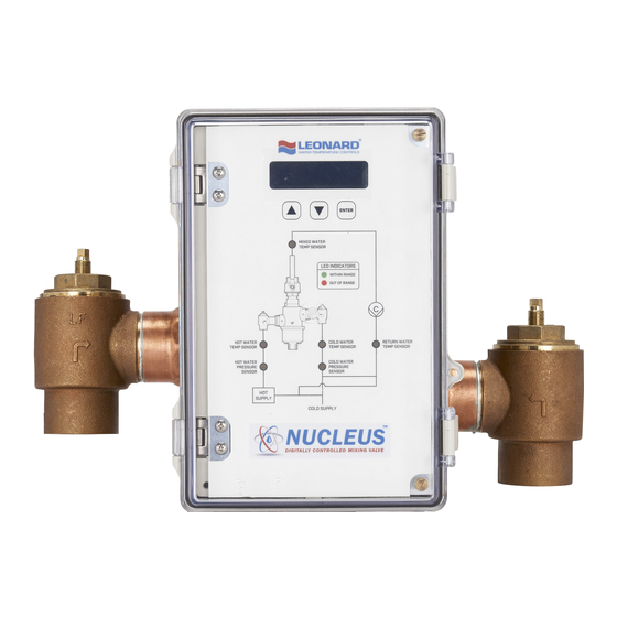
1. Leonard Nucleus Valves are factory pre-assembled and
tested and include digital mixing valve and controls
which function as a system to meet both high and low
demand for tempered water.
2. System should be installed at a location where it can
easily be cleaned, adjusted or repaired.
3. System supplies must be connected as shown (Hot-left,
Cold-right). Exercise caution when soldering.
Maximum Operating Pressure 125PSI (8.6 BAR) for Hot and Cold Water.
Hot Water Temperature Range: 120º - 180ºF (49º - 82ºC)
Cold Water Temperature Range: 39º - 80ºF (4º - 27ºC)
Temperature Adjustment Range: 65º - 180ºF (18º - 82ºC)
NUCLEUS VALVE
INSTALLATION
HOT INLET
MIXED OUTLET
INSTRUCTIONS PRIOR TO INSTALLATION
Model NV-150-LF – 1¼" Inlets, 1½" Outlet
Model NV-200-LF – 2" Inlets and Outlet
Model NV-300-LF – 3" Inlets and Outlet
1360 Elmwood Avenue, Cranston, RI 02910 USA
Phone: 401.461.1200 Fax: 401.941.5310
info@leonardvalve.com
Email:
Web Site: http://www.leonardvalve.com
COLD INLET
WARNING: This product can expose you to
chemicals including lead, which is known to the State
!
of California to cause cancer. For more information, go
to
www.P65Warnings.Ca.gov
4. Flush pipes thoroughly after system has been
connected.
5. This assembly
MUST be piped according to
LEONARD'S REQUIRED PIPING METHOD W.
6. Refer to pages 2-4 of this bulletin for correct Setup
Instructions.
Bulletin NUC-1
August, 2018
1
Advertisement


Need help?
Do you have a question about the NUCLEUS VALVE NV-150-LF and is the answer not in the manual?
Questions and answers