Advertisement
INSTALLATION ADJUSTMENT SERVICE
IMPORTANT! Provide serial number when ordering parts!!
INSTALLATION AND FIELD ADJUSTMENTS ARE THE
RESPONSIBILITY OF INSTALLER. READ ALL
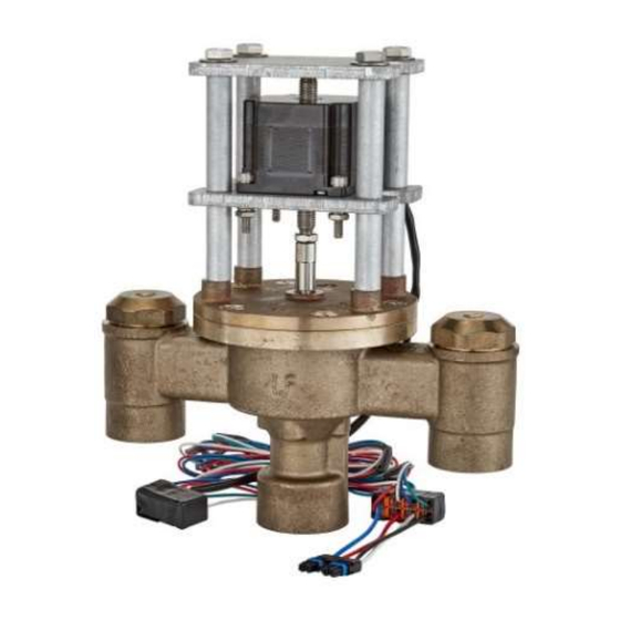
1. Leonard Proton Valves are factory pre-assembled and
tested and include digital mixing valve and controls
which function as a system to meet both high and low
demand for tempered water.
2. System should be installed at a location where it can
easily be cleaned, adjusted or repaired.
3. System supplies must be connected as shown (Hot-left,
Cold-right). Exercise caution when soldering.
Model PNV-150-LF-LCV – 1.25" Inlets, 1.5" Outlet (less check valves)
Check valves are recommended to prevent cross-flow on "LCV" models
Model PNV-200-LF-LCV – 2" Inlets and 2"Outlet (less check valves)
Model PNV-300-LF-LCV – 3" Inlets and 3"Outlet (less check valves)
Check valves are recommended to prevent cross-flow on "LCV" models
Maximum Operating Pressure 200PSI (13.8 BAR), valve only
Hot Water Temperature Range: 120º - 180ºF (49º - 82ºC)
Cold Water Temperature Range: 39º - 80ºF (4º - 27ºC)
Temperature Adjustment Range: 65º - 180ºF (18º - 82ºC)
PROTON VALVE
INSTRUCTIONS PRIOR TO INSTALLATION
Model PNV-100-LF – 3/4" Inlets, 1" Outlet
Model PNV-125-LF – 1" Inlets and 1.25"Outlet
Model PNV-150-LF – 1.25" Inlets, 1.5" Outlet
Model PNV-200-LF – 2" Inlets and 2"Outlet
Model PNV-300-LF – 3" Inlets and 3"Outlet
1360 Elmwood Avenue, Cranston, RI 02910 USA
Phone: 401.461.1200 Fax: 401.941.5310
Email:
info@leonardvalve.com
Web Site: http://www.leonardvalve.com
4. Flush pipes thoroughly after system has been
connected.
5. This assembly MUST be piped according to
LEONARD'S REQUIRED PIPING METHOD W.
6. Refer to pages 2-3 of this bulletin for correct Setup
Instructions.
7. Suitable for indoor use only
Bulletin PNV-1
June 2024
WARNING: This product can
expose
you
to
chemicals
including lead, which is known
to the State of California to
cause
cancer.
For
more
information,
go
to
www.P65Warnings.Ca.gov
!
1
Advertisement
Table of Contents

Related Manuals for Leonard PNV-150-LF


Summarization of Contents
Proton Valve Installation and Service
General Installation Instructions
Key steps for proper valve installation and system setup.
Proton Valve Model Specifications
Lists available models with inlet/outlet sizes.
Proton 1.0 Setup Instructions
Control Box and User Interface
Describes the digital display, keypad, and wiring connections.
Initial Power Up and Valve Sweep
Explains the automatic motor calibration process on first power.
Proton 1.0 Installation Procedure
Piping Method W Compliance
Specifies the required piping configuration for optimal performance.
Mounting and Wiring Connections
Details mounting the control box and connecting probes and motor.
Powering Up and Alignment Check
Steps for initial power-up and verifying correct valve alignment.
Proton 1.0 Temperature Scale Configuration
Setting Fahrenheit or Celsius Units
Instructions on changing temperature units via a jumper.
Proton 1.0 User Interface Operation
Home Screen and Sweep Value Display
Explains the main display showing current and setpoint temperatures.
Temperature Adjustment Process
Step-by-step guide to changing the desired outlet temperature.
Navigating Standard Menu Options
How to scroll through available menu screens and features.
Proton 1.0 Menu and Calibration Screens
Main Power Supply and Firmware Display
Shows screens for viewing power input and software version.
RTD Probe Calibration Procedure
Steps to calibrate the temperature sensor.
Proton 1.0 Calibration Procedures
Full Valve Sweep Count Calibration
Entering the initial valve sweep value for diagnostics.
Returning to the Home Screen Post-Calibration
How to exit calibration mode.
Proton 1.0 Error Code Diagnostics
Error Code 1: Check Probe
Identifies issues with the temperature probe connection or wiring.
Error Code 2: Valve Service Required
Indicates potential mechanical wear or low sweep value.
Error Code 3: T3 High or Low
Alerts to outlet temperature deviations from the setpoint.
Proton 2.0, 2.5 & 3.0 Setup Instructions
Control Box and Wiring Overview
Describes the control box, its connections, and the initial sweep function.
Initial Power Up and Valve Sweep
Explains the automatic motor calibration process on first power.
Proton 2.0, 2.5 & 3.0 Installation Procedure
Piping Method W and Valve Mounting
Specifies required piping and valve body mounting.
Control Box Connector Details
Details the 10-pin and 12-pin connectors for various inputs.
Powering Up and Initial Sweep
Steps for powering up and verifying the initial valve sweep.
Proton 2.0, 2.5 & 3.0 User Interface Operation
Home Screen and Sweep Value Display
Explains the main display showing current and setpoint temperatures.
Temperature Adjustment Process
Step-by-step guide to changing the desired outlet temperature.
Navigating Standard Menu Options
How to scroll through available menu screens and features.
Proton 2.0, 2.5 & 3.0 Menu Screen Functions
Main Power Supply and Firmware Revision
Shows screens for viewing power input and software version.
Mode Display and Configuration
Displays the controller's operating mode.
Proton 2.0, 2.5 & 3.0 Optional Menu Screens
Cold Water Inlet Temperature Display
Shows the temperature of the cold water supply.
Hot Water Inlet Temperature Display
Shows the temperature of the hot water supply.
Return Water Temperature Display
Shows the temperature of the mixed water return.
Proton 2.0, 2.5 & 3.0 Calibration Procedures
Outlet Probe Calibration
Adjusting the outlet temperature sensor reading.
Hot Water Probe Calibration
Adjusting the hot water inlet temperature sensor reading.
Proton 2.0, 2.5 & 3.0 Calibration Procedures (Continued)
Cold Water Probe Calibration
Adjusting the cold water inlet temperature sensor reading.
Return Water Probe Calibration
Adjusting the return water temperature sensor reading.
Proton 2.0, 2.5 & 3.0 Advanced Calibration Settings
Full Valve Sweep Count Entry
Inputting the initial sweep value for diagnostics.
Temperature Scale Setting (Fahrenheit/Celsius)
Selecting the display unit for temperature.
Bacnet Capability Configuration
Enabling or disabling Bacnet communication.
Proton 2.0, 2.5 & 3.0 Exiting Calibration Mode
Returning to the Home Screen
How to exit calibration and return to the main display.
Proton 2.0, 2.5 & 3.0 Error Code Diagnostics
Error Code 1: Check Probe
Indicates a problem with the temperature probe.
Error Code 2: Valve Service Required
Signals potential mechanical issues or low sweep values.
Error Code 3: T3 High or Low
Alerts to deviations in outlet temperature from the setpoint.
Proton 2.0, 2.5 & 3.0 Disinfection Mode Introduction
Entering Disinfection Mode
Procedure to activate the disinfection function.
Setting Minimum Disinfection Temperature
Configuring the lowest acceptable temperature for the cycle.
Proton 2.0, 2.5 & 3.0 Disinfection Mode Configuration
Setting Maximum Disinfection Temperature
Configuring the highest acceptable temperature for the cycle.
Configuring Warmup Time
Setting the time for the valve to reach disinfection temperatures.
Setting Disinfection Cycle Duration
Defining the length of the disinfection cycle.
Proton 2.0, 2.5 & 3.0 Disinfection Mode Operation
Confirming Disinfection Parameters
Reviewing all set parameters before initiating the cycle.
Warmup Countdown and Status Monitoring
Tracking the progress of the warmup phase.
Proton 2.0, 2.5 & 3.0 Disinfection Mode Execution
Stabilization Phase Monitoring
Ensuring stable temperatures before the main disinfection starts.
Disinfection Duration Countdown
Tracking the active disinfection time.
Cooldown and Return to Home Screen
Process after disinfection cycle completion.
Sensor Troubleshooting and Replacement
Identifying Sensor Disconnection Errors
Describes the "Check Probe" error and its causes.
Sensor Replacement Parts and Procedure
Details the steps and parts needed for sensor replacement.
Temperature Probe Installation and Replacement
Installing Compression Fittings
Detailed instructions for correctly installing fittings.
Installing RTD Temperature Probes
Steps for inserting the probe into the fitting.
Replacement Probe Part Number
Specifies the part number for replacement probes.
Required Piping Method W
Piping Diagram and Component Layout
Visual representation of the recommended piping configuration.
Notes on Piping Installation Requirements
Important considerations for compliant installation.
BMS Connection and Configuration
Connecting Control Box to BMS
Instructions for linking the valve to a Building Management System.
Laptop Connection via Micro-USB
How to connect a laptop for configuration.
Using Leonard NPU Software for Setup
Guidance on using the NPU application.
Configuring Network Protocols and Parameters
Setting up BACnet or Modbus communication.
BMS Communication Protocol Objects
BACnet Object List for BMS Integration
List of objects for BACnet communication.
Modbus Object List for BMS Integration
List of objects for Modbus communication.
Wi-Fi Network Connection Procedure
Enabling Wi-Fi in Calibration Mode
Steps to access Wi-Fi settings.
Configuring Wi-Fi Network Parameters
Inputting network credentials and settings.
Accessing the Proton Dashboard via Browser
How to view the valve's status online.
PNV100 & PNV125 Parts and Kits
Kit Types and Included Components
Details on O-ring, repair, and check kits for PNV100/125.
Exploded View and Part Identification
Diagram showing numbered parts for PNV100/125.
PNV150 & PNV200 Parts and Kits
Kit Types and Included Components
Details on O-ring and repair kits for PNV150/200.
Exploded View and Part Identification
Diagram showing numbered parts for PNV150/200.
Check Valve Assembly Parts
PNV-150-LF 1-1/4" Check Valve Parts
Lists specific components for PNV-150-LF check valves.
PNV-200-LF 2" Check Valve Parts
Lists specific components for PNV-200-LF check valves.
PNV300 Parts and Kits
Kit Types and Included Components
Details on O-ring and repair kits for PNV300.
Exploded View and Part Identification
Diagram showing numbered parts for PNV300.
Controller Model Identification
Distinguishing Controller Versions
Visual comparison of 1.0 vs 2.0, 2.5, 3.0 controllers.
Replacement Cover Assembly Part Numbers
Table mapping valve models to cover assembly part numbers.
Valve Performance Specifications and Warranty
Pressure Drop Performance Charts
Data on pressure drop across different flow rates.
Limited Warranty Terms and Conditions
Legal information regarding product warranty.
Need help?
Do you have a question about the PNV-150-LF and is the answer not in the manual?
Questions and answers