Advertisement
INSTALLATION ADJUSTMENT SERVICE
IMPORTANT! Provide serial number when ordering parts!!
INSTALLATION AND FIELD ADJUSTMENTS ARE THE
RESPONSIBILITY OF INSTALLER. READ ALL
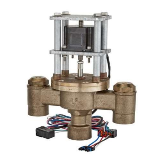
1. Leonard Proton Valves are factory pre-assembled and
tested and include digital mixing valve and controls
which function as a system to meet both high and low
demand for tempered water.
2. System should be installed at a location where it can
easily be cleaned, adjusted or repaired.
3. System supplies must be connected as shown (Hot-left,
Cold-right). Exercise caution when soldering.
Model PNV-150-LF-LCV – 1.25" Inlets, 1.5" Outlet (less check valves)
Check valves are recommended to prevent cross-flow on "LCV" models
Model PNV-200-LF-LCV – 2" Inlets and 2"Outlet (less check valves)
Model PNV-300-LF-LCV – 3" Inlets and 3"Outlet (less check valves)
Check valves are recommended to prevent cross-flow on "LCV" models
Maximum Operating Pressure 200PSI (13.8 BAR), valve only
Hot Water Temperature Range: 120º - 180ºF (49º - 82ºC)
Cold Water Temperature Range: 39º - 80ºF (4º - 27ºC)
Temperature Adjustment Range: 65º - 180ºF (18º - 82ºC)
PROTON VALVE
INSTRUCTIONS PRIOR TO INSTALLATION
Model PNV-100-LF – 3/4" Inlets, 1" Outlet
Model PNV-125-LF – 1" Inlets and 1.25"Outlet
Model PNV-150-LF – 1.25" Inlets, 1.5" Outlet
Model PNV-200-LF – 2" Inlets and 2"Outlet
Model PNV-300-LF – 3" Inlets and 3"Outlet
1360 Elmwood Avenue, Cranston, RI 02910 USA
Phone: 401.461.1200 Fax: 401.941.5310
Email:
info@leonardvalve.com
Web Site: http://www.leonardvalve.com
4. Flush pipes thoroughly after system has been
connected.
5. This assembly MUST be piped according to
LEONARD'S REQUIRED PIPING METHOD W.
6. Refer to pages 2-3 of this bulletin for correct Setup
Instructions.
7. Suitable for indoor use only
Bulletin PNV-1
June 2024
WARNING: This product can
expose
you
to
chemicals
including lead, which is known
to the State of California to
cause
cancer.
For
more
information,
go
to
www.P65Warnings.Ca.gov
!
1
Advertisement
Table of Contents

Related Manuals for Leonard PNV-200-LF


Summary of Contents for Leonard PNV-200-LF
- Page 1 INSTALLATION AND FIELD ADJUSTMENTS ARE THE RESPONSIBILITY OF INSTALLER. READ ALL INSTRUCTIONS PRIOR TO INSTALLATION 1. Leonard Proton Valves are factory pre-assembled and 4. Flush pipes thoroughly after system has been tested and include digital mixing valve and controls connected.
- Page 2 WARNING The Leonard Proton Digital Mixing Valve is an electronically controlled device utilizing DC circuitry. The connection of the Electronic Control Box to the Mechanical Valve Components is very simple. There is a 3-wire RTD Temperature Probe as well as a 4-wire Motor Harness that must be connected and plugged into the box on the left and middle (respectively) connection points on the bottom of the Control Box.
- Page 3 PROTON 1.0 – INSTALLATION INSTRUCTIONS 1. The Proton Unit MUST be piped according to Leonard Required Piping Method W (see page 25). 2. Mount valve body, outlet facing down, and plumb inlet and outlet connections. DO NOT introduce water to the valve until completion of these instructions.
- Page 4 PROTON 1.0 - DEGREES “F” OR “C” Protons can display in either degrees “F” Fahrenheit or degrees “C” Celsius. The units come standard as degrees “F” Fahrenheit. To change the units to degrees “C” Celsius it is as simple as removing a “jumper” on the board on the back on the control box as seen in the pictures below.
- Page 5 Proton 1.0 – User Screens Home Screen: Current outlet temperature and Set point temperature Home Screen: After initial “Full Sweep” the bottom line of the digital display indicates the measured sweep value of the valve, hot to cold. Please record this numerical value as you will need it for calibration Screen 2 below.
- Page 6 Menu Screen 1: Main Power Supply Pressing ▼ 1 time displays POWER: 12.82 This indicates the input supply voltage to the main control board, Volts DC, and should always be at least 12 VDC Menu Screen 2: Firmware Revision Pressing ▼ 2 times displays FW Rev: X.X.X.X This screen shows the current version of Firmware loaded into the Proton processor.
-
Page 7: Calibration Screen
Calibration Screen 2: Full Valve Sweep Counts The above Calibration Screen is used to enter the initial Full Valve Sweep Value obtained and recorded in Step #10 from initial power up. Press ENTER to input FVS value, it will flash. Use ▲ button to adjust FVS counts value and advance until it agrees with the Initial Sweep Value recorded in Step #10 above. - Page 8 Proton 1.0 Digitally Controlled Mixing Valve Error Codes Error codes are displayed on the LCD screen. Errors must be manually cleared by pressing ENTER and the error condition has been corrected. There are 2 Error Codes on the Proton Digitally Controlled Mixing Valve. Error codes are listed below: Error Code 1: Check Probe (Temperature Probe) This Error indicates that the RTD Temperature Probe installed...
- Page 9 WARNING The Leonard Proton Digital Mixing Valve is an electronically controlled device utilizing DC circuitry. The connection of the Electronic Control Box to the Mechanical Valve Components is very simple. There is a 3-wire RTD Temperature Probe as well as a 4-wire Motor Harness that must be connected and plugged into the box on the far left and right (respectively) connection points on the bottom of the Control Box.
-
Page 10: Pin Connector
PROTON 2.0, 2.5, 3.0 – INSTALLATION INSTRUCTIONS 1. The Proton Unit MUST be piped according to Leonard Required Piping Method W (see page 25). 2. Mount valve body, outlet facing down, and plumb inlet and outlet connections. DO NOT introduce water to the valve until completion of these instructions. - Page 11 Proton 2.0, 2.5 and 3.0 – User Screens Home Screen: Current outlet temperature and Set point temperature Home Screen: After initial “Full Sweep” the bottom line of the digital display indicates the measured sweep value of the valve, hot to cold. Please record this numerical value as you will need it for calibration Screen 2 below.
- Page 12 Menu Screen 3: Mode Pressing ▼ 3 times displays Mode: Proton This screen shows the Mode in which the controller is programmed. In this case, the controller should always read Proton. If another mode is displayed contact the Leonard Valve factory.
- Page 13 Optional Menu Screen 4: Cold Water Temperature Pressing ▼ 1 time displays Cold temp: XXX F or C This indicates the cold water inlet temperature to the Proton mixing valve. Optional Menu Screen 5: Hot Water Temperature Pressing ▼ 2 times displays Hot temp: XXX F or C This indicates the hot water inlet temperature to the Proton mixing valve.
- Page 14 From ANY screen, the user must enter the CALIBRATION Menu in order to record the initial numerical Full Valve Sweep value (recorded in Step 10 above) for comparison to future Valve Sweep Values for any maintenance warnings moving forward on this device. To Enter Calibration: Press the ▲▼buttons simultaneously.
- Page 15 Calibration Screen 3: Cold Water Probe Calibration This Calibration Screen is used if the cold water temperature display differs significantly from a downstream temperature measurement value. It is a way to OFFSET the outlet temperature in order to agree with another temperature measurement value. Press ENTER to adjust Cal value, it will flash.
- Page 16 Calibration Screen 5: Full Valve Sweep Count The above Calibration Screen is used to enter the initial Full Valve Sweep Value obtained and recorded in Step #10 from initial power up. Press ENTER to input FVS value, it will flash. Use ▲ button to adjust FVS counts value and advance until it agrees with the Initial Sweep Value recorded in during initial power up.
- Page 17 To Exit Calibration: Press the ▲▼buttons simultaneously. This will return you to the HOME Screen: Home Screen: Current outlet temperature and Set point temperature The user is returned to the ‘Home Screen’ which displays current temperature as measured on valve outlet and the set point temperature on the line below. Note: A large negative value displayed at the Cur temp line indicates the sensor is damaged or not properly wired to the main control board.
- Page 18 Proton 2.0, 2.5 & 3.0 Digitally Controlled Mixing Valve Error Codes Error codes are displayed on the LCD screen. Errors must be manually cleared by pressing ENTER and the error condition has been corrected. Error Codes on the Proton Digitally Controlled Mixing Valve are listed below. Error Code 1: Check Probe (Temperature Probe) This Error indicates that the Proton Valve has reached less than...
- Page 19 Proton 2.0, 2.5 & 3.0 Digitally Controlled Mixing Valve Disinfection Mode WARNING: The Proton Digitally Controlled Mixing Valve is equipped with the ability to program the valve to move to full hot position, which will allow ONLY high temperature hot supply water to enter the device and subsequently deliver that high temperature water downstream of the device.
- Page 20 Proton 2.0, 2.5 & 3.0 Digitally Controlled Mixing Valve Disinfection Mode Screen 3: Maximum Disinfection Temperature Set the maximum temperature the disinfection cycle will run at. If the outlet temperature falls below the minimum disinfection temperature the cycle will end. Default temperature is 185°F. Use the ▲▼buttons to change value and press ENTER to advance to the next screen.
- Page 21 Proton 2.0, 2.5 & 3.0 Digitally Controlled Mixing Valve Disinfection Mode Confirmation Screens Confirm each of the previous four parameters settings by pressing ENTER for each. Pressing either arrow will automatically end the disinfect cycle. Once a disinfection cycle is initiated, the top line of the controller will display Warmup along with a timer that is counting down.
- Page 22 Proton 2.0, 2.5 & 3.0 Digitally Controlled Mixing Valve Disinfection Mode When the outlet temperature reaches the Minimum disinfection temperature, the warmup screen will automatically change to a countdown of the Stabilization time. This lasts for 1 minute and is meant to ensure stable disinfection temperatures before the disinfection cycle timer starts.
- Page 23 Proton Control Box. If the sensor is properly connected to the controller and the condition persists, then the sensor needs to be replaced. Contact Local Leonard Valve Representation for part number 803203 – Outlet Sensor (All Proton Models) 809001 –...
- Page 24 INSTALLING AND REPLACING TEMPERATURE PROBES The RTD temperature probes used with Proton assemblies are simple to install. On the valve body the temperature probe is connected to the valve with a ¼” MNPT x ⅛”compression fi ng. Teflon tape and a small amount of thread sealant should be used on the NPT side of the fittings.
- Page 25 - FOR MULTIPLE TEMPERED LOOPS, A BALANCING VALVE AND CHECK VALVE MUST BE INSTALLED ON EACH LOOP AFTER TEMPERED FIXTURES Leonard Proton Digital Mixing Valves are simple NOTE: Leonard Proton Digital Mixing Valves must in design and may be easily cleaned, adjusted be regularly maintained to provide best and repaired.
- Page 26 Power up the Proton control box. Power must be on to be able to configure BMS settings. Connect a laptop to the Proton control box via the Micro-USB port located on the bottom of the box. Download LEONARD NPU. After unzipping the file, navigate to the NPU application. See www.leonardvalve.com for the files.
-
Page 27: Bacnet Object List
BACnet OBJECT LIST Object Default COV Active Inactive Number of Object Name Type Instance Units Increment Text Text Polarity States Notes Analog TempOut Input no-units °F or °C Analog TempHotIn Input no-units °F or °C Analog TempColdIn Input no-units °F or °C Analog TempReturnIn Input... -
Page 28: Wi-Fi Connection Procedure
Open the Proton3ToolV19 and select the connection port that the controller is connected to. This tool can be found at the Leonard Valve website, www.leonardvalve.com. Once connected, press the “Query” button to bring up the current settings. If a new box is being set up, the fields will be completely blank. - Page 29 PNV100 PNV125 KIT TYPE INCLUDES KIT 1/PNV1 KIT 1/PNV2 O-RING KIT 1 - 4 KIT R/PNV1 KIT R/PNV2 COMPLETE REPAIR 1 - 6 KIT 2/50 KIT 2/50 CHECK KIT 7 - 10 #14 cover assembly includes • Cover, plates • Motor •...
- Page 30 PNV150 / PNV200 KIT TYPE INCLUDES KIT R/NV COMPLETE REPAIR 1 - 8 KIT 1/NV O-RING 1 - 5 #10 cover assembly includes • Cover, plates • Motor • Stem • O-rings • Shuttle All fully assembled ITEM # DESCRIPTION QTY.
- Page 31 PNV-150-LF, 1-1/4” CHECKS DESCRIPTION INCLUDES KIT 4/984 REBUILD KIT 11-15 ITEM # DESCRIPTION QTY. PART # / KIT # LOWER STEM & PACKING KIT 4/984 SCREEN KIT 4/984 SPRING,CHECK KIT 4/984 O-RING, COVER KIT 4/984 O'RING, UPPER STEM KIT 4/984 STEM, UPPER CHECK 1761 CHECK BONNET...
- Page 32 PNV300 KIT TYPE INCLUDES KIT R/NV3 COMPLETE REPAIR 1 - 8 KIT 1/NV3 O-RING 1 - 5 #10 cover assembly includes • Cover, plates • Motor • Stem • O-rings • Shuttle All fully assembled ITEM # DESCRIPTION QTY. PNV300 O-RING, COVER KIT 1/NV3, KIT R/NV3 O-RING, COVER...
- Page 33 PLEASE NOTE: Replacement cover assemblies will vary depending on which controller is with the mixing valve, see below to distinguish between the two, 2.0, 2.5, 3.0 VALVE DESCRIPTION 2.0, 2.5, 3.0 PNV-100 COVER ASSEMBLY 892400 892499 PNV-125 COVER ASSEMBLY 890400 890499 PNV-150 COVER ASSEMBLY 898105...
-
Page 34: Limited Warranty
Leonard’s instructions, for a period of one year from the date of shipment. During this period, Leonard will at its option repair or replace any product, or part thereof, which shall be returned, freight prepaid, to the Leonard factory and determined by Leonard to be defective in materials or workmanship.
Need help?
Do you have a question about the PNV-200-LF and is the answer not in the manual?
Questions and answers