Table of Contents
Advertisement
Quick Links
Advertisement
Table of Contents

Related Manuals for SIGLENT SNA5002A


Summarization of Contents
2 Safety Requirement
2.1 Safety terms and symbols
Explains hazardous terms and symbols used in the manual and on the instrument.
3 Product Introduction
3.1 General Description
Provides an overview of the SNA5000A series and its capabilities.
3.2 Features
Lists the key technical specifications and features of the SNA5000A series VNAs.
5 Quick Start
5.1 Dimensions
Details the physical dimensions of the vector network analyzer.
5.2 Power supply
Explains how to connect the instrument to a power source.
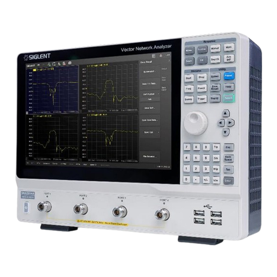
5.3 Front panel
Describes the layout and components of the instrument's front panel.
5.3.1 Functional keyboard
Details the functions of the keys on the front panel's functional keyboard.
5.4 Rear panel
Illustrates and describes the connectors and ports on the instrument's rear panel.
5.6 User interface
Provides an overview of the graphical user interface elements.
6 Set Up a Measurement
6.1 Measurement Classes
Explains categories of measurements that can coexist on a channel.
6.2 Measurement parameters
Covers parameters like S-parameters, balanced measurements, and receivers.
6.2.1 S parameters
Defines S-parameters and lists common measurements using them.
6.2.2 Balanced Measurement
Explains measurements for balanced devices and mixed-mode S-parameters.
6.3 Frequency range
Details how to set the frequency span for measurements.
6.4 Power level
Explains how to configure output power settings.
6.5 Sweep
Covers sweep types, points, and their settings.
6.6 Trigger
Describes trigger sources, range, and modes for measurement synchronization.
6.7 Data format
Explains how to display measurement data in various formats.
6.8 Scale
Covers scaling, reference level, and position settings for trace display.
7 Measurement Calibration
7.1 Overview
Explains the importance of calibration for accurate measurements.
7.2 Calibration type
Compares common S-parameter calibration types.
7.4 Basic Cal
Guides through performing basic calibration procedures.
7.4.1 Open Response Calibration
Details the steps for open-circuit response calibration.
7.4.6 SOLT calibration (two ports)
Covers the SOLT calibration method for two-port measurements.
7.5 Cal Kit management
Explains how to manage calibration kits, including creating custom ones.
7.6 Power Cal
Covers internal source and receiver power calibration procedures.
8 Data Analysis
8.1 Marker
Explains how to use markers to display measurement data.
8.1.1 Ordinary marker
Describes how to create and manage ordinary markers.
8.1.3 Marker setting
Covers settings for markers, including difference display and fixed markers.
8.2 Marker search function
Details how to search for peaks, targets, and bandwidth.
8.5 Equation editor
Explains how to create custom measurement formulas.
8.7 Limit test
Covers limit testing, including line and point limits.
10 Guide For the TDR Option
10.1 Overview
Introduces the TDR option, its functions, and advantages.
10.3 TDR Setup Wizard
Guides users through initial TDR setup.
10.4 Calibration for TDR Option
Explains Deskew and Deskew & Loss Compensation for TDR.
10.4.1 Deskew
Details the procedure for performing Deskew calibration.
10.4.2 Deskew & Loss Compensation
Describes Deskew and Loss Compensation calibration steps.
10.5 TDR Channel Setup
Covers channel setup for TDR measurements.
10.7 TDR Data Analysis & Output
Explains TDR data analysis tools and file output options.
11 Guide For the SA Option
11.1 Overview
Introduces the Spectrum Analysis (SA) option and its capabilities.
11.4 Spectrum Analyzer Settings
Details the configuration settings for the spectrum analyzer.
11.4.1 SA Setting Tab
Covers frequency settings, span, and step for SA.
11.4.2 SA Tab Processing setup
Explains RBW, VBW, and averaging type settings.
11.4.4 Advanced Tab
Details advanced settings for signal processing in SA.
11.5 Spectrum Analysis measurement
Covers specific SA measurements like Channel Power and ACPR.
11.5.1 Marker → SA
Explains how to use markers for SA measurements.
11.5.2 Channel Power
Details how to measure channel power and spectral density.
11.5.3 ACPR
Explains measurement of Adjacent Channel Power Ratio.
11.5.4 Occupied BW
Covers measurement of Occupied Bandwidth.
11.5.7 Spectrum Monitor
Describes the spectrum monitor and waterfall chart feature.
12 The Frequency Offset Mode
12.1 Overview
Introduces frequency offset sweep for measuring frequency conversion devices.
12.2 Frequency Offset Mode
Details the functionality of Frequency Offset Mode (FOM).
13 Scalar Mixer Measurements (SMM Option)
13.1 Create an SMM measurement
Guides on creating a new Scalar Mixer Measurement channel.
13.2 Configure the Scalar mixer setup
Covers the configuration of sweep, power, frequency, and setup for mixer measurements.
13.2.1 Sweep Tab-Mixer Measure Setup box
Details sweep type and related settings for mixer measurements.
13.2.2 Power Tab-Mixer Measure Setup box
Explains input/output power settings for mixer measurements.
13.2.3 Mixer Frequency Tab-Mixer Measure Setup box
Details mixer frequency settings and configuration rules.
13.5 Do the SMM Calibration
Explains the procedure for SMM calibration.
14 Pulse Measurement (PM Option)
14.1 Overview
Introduces pulse measurement capabilities for testing devices with continuous signals.
14.2 Pulse Measurement Settings
Covers settings for pulse width, period, and timing.
15 Material Measurement (MT Option)
15.1 Overview
Introduces material measurement and its applications.
15.3 Configure the Material Measurement Setup
Details setup tabs for material measurement.
15.3.1 Preset Tab
Covers preset settings for material measurement.
15.3.2 Measurement Model Tab
Explains different measurement models for materials.
15.3.3 Sample Holder Tab
Details settings for sample holder and waveguide.
15.4 Waveguide TRL Calibration
Explains waveguide TRL calibration procedures.
16 External Switch Matrices (SWM Option)
16.1 Overview
Introduces the benefits of external switch matrices for port expansion.
16.3 Matrix setup step
Details the steps for setting up external matrix switches.
16.3.2 Establish the physical connection
Explains how to physically connect the VNA and switch matrix.
16.3.3 Define the RF configuration
Covers defining RF connections between VNA and switch matrices.
16.3.4 Setting S Parameters
Details how to configure S-parameters for expanded ports.
17 System setting
17.1 System Configuration
Details firmware upgrade, file browser, and date/time settings.
17.1.1 Firmware upgrade
Provides instructions for upgrading the instrument's firmware.
17.2 Communication interface setting
Covers LAN, VNC, and Web settings for communication.
17.7 Self-Test
Covers key, touch screen, and performance tests.
18 Service and Support
18.1 Ordering and activating the options
Explains how to order and activate instrument options.
18.3 Contact SIGLENT
Lists contact information for SIGLENT support.
Need help?
Do you have a question about the SNA5002A and is the answer not in the manual?
Questions and answers