Table of Contents
Advertisement
Quick Links
Advertisement
Table of Contents

Subscribe to Our Youtube Channel
Related Manuals for SIGLENT SSA3000X Series


Summary of Contents for SIGLENT SSA3000X Series
- Page 1 SSA3000X Spectrum Analyzer User Manual UM0703X-E03A...
- Page 2 Declaration SIGLENT products are protected by patent law worldwide SIGLENT reserves the right to modify or change parts of or all the specifications or pricing policies at company’s sole decision. Information in this publication replaces all previously corresponding material.
-
Page 3: General Safety Summary
SIGLENT General Safety Summary Carefully read the following safety precautions to avoid any personal injury or damage to the instrument and any products connected to it. To avoid potential hazards, please use the instrument as specified. Use Proper AC Power Line Only the power cord designed for the instrument and authorized by local country should be used. -
Page 4: Safety Terms And Symbols
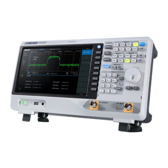
Safety Terms and Symbols Terms on the product. These terms may appear on the product: DANGER Indicates direct injuries or hazards that may happen. WARNING Indicates potential injuries or hazards that may happen. CAUTION Indicates potential damages to the instrument or other property that may happen. - Page 5 SIGLENT Overview SSA3000X series spectrum analyzer has a frequency range from 9 kHz up to 2.1 GHz/3.2 GHz; it is light weight and small size, with a user friendly interface, concise style of display, reliable measurement precision and plenty of RF measurement functions. Applicable to research and development, education, production, maintenance and other related fields that meets a wider range of application requirements.
-
Page 6: Table Of Contents
Contents Guaranty and Declaration ....................... II General Safety Summary ......................III Safety Terms and Symbols ....................... IV Chapter 1 Quick Start ......................1 General Inspection ....................2 Appearance and Dimension ..................2 Preparing for Use ....................3 1.3.1 Adjust the Supporting Legs ................3 1.3.2 Connect to AC Power Supply ............... - Page 7 SIGLENT 2.3.3 Marker Fn....................44 2.3.4 Peak ......................47 Measurement ......................49 2.4.1 Meas ......................49 2.4.2 Meas setup ....................50 System ........................57 2.5.1 System ......................57 2.5.2 Display ......................59 2.5.3 File ......................60 Shortcut Key ......................63 2.6.1...
-
Page 8: Chapter 1 Quick Start
SIGLENT Chapter 1 Quick Start This chapter guides users to quickly get familiar with the appearance, dimensions, front/ rear panel and the user interface, as well as announcements during first use of SSA3000X series spectrum analyzer. Subjects in this chapter: ... -
Page 9: General Inspection
The consigner or carrier will be responsible for damages to the instrument resulting from shipment. SIGLENT will not provide free maintenance or replacement. Inspect the instrument If the instrument is found to be damaged, defective or fails in electrical or mechanical tests, please contact SIGLENT. -
Page 10: Preparing For Use
SIGLENT 1.3 Preparing for Use 1.3.1 Adjust the Supporting Legs Adjust the supporting legs properly to use them as stands to tilt the Spectrum Analyzer upwards for stable placement as well as easier operation and observation of the instrument. Figure 1-3 Before adjusting Figure1-4 After adjusting 1.3.2 Connect to AC Power Supply... -
Page 11: The Front Panel
SIGLENT 1.4 The Front Panel Figure 1-6 The Front Panel Table 1-1 Front Panel Description Description Description User Graphical Interface Menu Control Keys Function Keys Knob Arrow Keys RF Input Numeric Keyboard TG Output Earphone interface USB Host Power Switch 1.4.1 Front Panel Function Keys... - Page 12 SIGLENT Table 1-2 Function keys description Control Keys Description Set the parameters of freqency, and Peak→CF, CF→Step Frequency Set the parameters of span, and X-scale(Log-Linear) setup Span Amplitude Set the parameters of amplitude, including Ref Level, Attenuator, Preamp, etc ;...
-
Page 13: Front Panel Key Backlight
SIGLENT 1.4.2 Front Panel Key Backlight The on/off state and the color of the backlights of some keys at the front panel indicate the working state of the spectrum analyzer. The states are as listed below. Power Switch Flash on and off alternatively, in breathing state: indicate the unit is in stand-by state. -
Page 14: Front Panel Connectors
SIGLENT During parameter editing process, press this key to clear the inputs in the active function area and exit parameter input. When the instrument is in remote mode, use this key to return to local mode. Enter In parameter editing, the system will complete the input and insert a default unit for the parameter. -
Page 15: Rear Panel
SIGLENT CAUTION For fear of damaging your hearing, please turn the volume down to zero and gradually turn the volume up after putting on the earphone. TG SOURCE The TG SOURCE can be connected to a receiver through a cable with a N male connector. - Page 16 SIGLENT Handle Pull up the handle vertically for easy carrying of the instrument. When you do not need the handle, press it down. USB Device interface The analyzer can serve as a “slave” device to connect external USB devices. Through this interface, a PC can be connected to control the analyzer remotely through programming or PC software.
-
Page 17: Display Annotations
Figure 1-11 User Interface Table 1-3 User Interface labels Name Description SIGLENT Logo of SIGLENT Reference level UNCAL When the sweep time less than the auto couple time, the measure result may be inaccuracy, then appear “UNCAL” Active function area... -
Page 18: Firmware Operation
SIGLENT means the instrument is upgrading Sweep time Sweep time Span/Stop Frequency The frequency range of the current sweep Sweep progress bar Sweep progress bar Pass/Fail status Pass/Fail status Video bandwidth Spectrum trace Spectrum trace Resolution bandwidth Center/Start frequency The frequency range of the current sweep Trace status Set the trace A\B\C\D parameter. -
Page 19: Enable Option
SIGLENT 1.7.2 Enable Option Refer to the procedures below to activate the options you have purchased. 1, Press System ->“Load Option” 2, Enter the license key in the onscreen window. Press Enter to confirm your input and terminate the license key input. Or 3, Load the .lic file provided by pressing File ->“Load”... -
Page 20: Parameter Setting
SIGLENT Enter Lower Menu (without parameter) Press the corresponding menu key to enter the lower menu. For example, press Calibration to enter the lower menu directly. Direct Execution Press the key to execute the corresponding function. For example, press Peak->CF to execute a peak search and set the center frequency of the analyzer to the frequency of the current peak signal. -
Page 21: Using Built-In Help
SIGLENT 3. Use the arrow keys When the parameter is editable (namely when the parameter is selected), you can increase or decrease the parameter value at the specific step using the direction keys. Press Frequency -> “Center Freq” ... -
Page 22: Chapter 2 Front Panel Operation
SIGLENT Chapter 2 Front Panel Operation This chapter describes in detail the function keys at the front panel and the associated functions. Subjects in this chapter: Basic Settings Sweep and Function Marker Measurement System ... -
Page 23: Basic Settings
SIGLENT 2.1 Basic Settings 2.1.1 Frequency Set the frequency parameters and functions of the analyzer. Restart sweeping every time when the frequency parameters are modified. The frequency range of a channel can be expressed by either of three groups of parameters: Start Frequency, Center Frequency and Stop Frequency. - Page 24 SIGLENT Table 2-2 Start Frequency Parameter Explanation Default 0 GHz Range Zero Span, 0 Hz ~ Full Span Nonzero Span, 0 Hz ~ (Full Span-100Hz) Unit GHz\MHz\kHz\Hz Knob Step Span>0, step=Span/200 Span=0, step=RBW/100 Min 1 Hz Direction Key Step Freq step...
- Page 25 SIGLENT Parameter Explanation Default Full Span/10 Range 1Hz ~ Full Span Unit GHz, MHz, kHz, Hz Knob Step Span>0, Step=Span/200 Span=0, Step=100 min 1 Hz Direction Key Step 1-2-5 sequence step Relation RBW, Span and related parameters 2.1.1.5 Peak -> CF Execute a peak search and use the frequency of the current peak as the center frequency (CF) of the analyzer.
-
Page 26: Span
SIGLENT Figure 2-2 After Peak -> CF 2.1.1.6 CF -> Step Set the current center frequency as the CF step. At this point, the CF step will switch to “Manual” mode automatically. This function is usually used with channel switching. Take harmonic waveform measurement for example: locate a signal at the center frequency of a channel, execute CF->Step and then press the down direction key continuously to measure each order of... - Page 27 SIGLENT VBW mode). Variation in the span, RBW or VBW would cause a change in the sweep time. In non-zero span mode, neither is “Video” trigger nor “1/△ time” readout function valid. Table 2-5 Span Parameter Explanation Default...
-
Page 28: Amplitude
SIGLENT 2.1.2.6 Last Span Set the span to the previous span setting. 2.1.2.7 X-Scale Set the scale type of X-axis to Lin or Log. In Log scale type, the frequency scale of X-axis is displayed in the logarithmic form. If the scale type of X-axis is in the logarithmic type form, the scale type will be switched into Lin when turning on Meas. - Page 29 SIGLENT current reference level automatic adjustment. Open the preamplifier, maximum input attenuation can be set to 51dB. When setting parameters do not meet the above formula, can adjust the reference level. Table 2-7 Attenuator Parameter Explanation Default 20 dB...
- Page 30 SIGLENT when the scale type is set to “log”. In process of using pay attention to the following points: By changing the scale, the amplitude range available is adjusted。 The Minimum range: reference level –10 × current scale value;...
-
Page 31: Auto Tune
SIGLENT 2.1.3.8 Correction Correct the amplitude in order to compensate for the gain or loss from external devices such as Antenna and Cable. When using this function, you can view the correction data table and save or load the current correction data. When amplitude correction is turn on, both the trace and related measurement results will be corrected. - Page 32 SIGLENT Figure 2-3 Before Auto Tune Figure 2-4 After Auto Tune SSA3000X User Manual 25...
-
Page 33: Sweep And Function
SIGLENT 2.2 Sweep and Function 2.2.1 BW Set the RBW (Resolution Bandwidth), VBW (Video Bandwidth), average type parameters of the analyzer and filter shape. 2.2.1.1 Resolution Bandwidth Set the resolution bandwidth in order to distinguish between signals which are close in frequency. - Page 34 SIGLENT 2.2.1.3 V/R Ratio Set the ratio of VBW to RBW. This value is different while measuring different kinds of signals: Sine signal: use 1 to 3 (for faster sweeps) Pulse signal: use 10 (to reduce the influence on the amplitude of transient signals) ...
-
Page 35: Trace
SIGLENT 2.2.2 Trace The sweep signal is displayed as a trace on the screen. 2.2.2.1 Select Trace Spectrum Analyzer allows for up to four traces to be displayed at the same time. Each trace has its own color (Trace 1 - Yellow, Trace 2 - Purple, Trace 3 - Light blue and Trace 4 - Green). All traces can be set parameter independently. - Page 36 SIGLENT 2. Max Hold Retains the maximum level for each trace point of the selected trace. Updates the data if a new maximum level is detected in successive sweeps. 3. Min Hold Display the minimum from multiple sweeps for each point of the trace and update the data if a new minimum is generated in successive sweeps.
-
Page 37: Detect
SIGLENT Table 2-15 Const Parameter Explanation Default Range -300 dB ~ 300 dB Unit 2.2.2.7 Output Z The result Z will show on screen in trace A, B, C as you choose. 2.2.2.8 Calculation Type Spectrum Analyzer provides the calculation types as shown below: X-Y+Ref→Z... -
Page 38: Sweep
SIGLENT 4. Normal Normal detector (also called rosenfell detector) displays the maximum value and the minimum value of the sample data segment in turn; namely for an odd-numbered data point, the maximum value is displayed; for an even-numbered data point, the minimum value is displayed. In this way, the amplitude variation range of the signal is clearly shown. - Page 39 SIGLENT Speed: Activates the default fast sweep time rule. Accuracy: Activates the normal sweep time rule to ensure the measurement accuracy. Speed sweep time rule provides a fast measurement function that decreases the sweep time. Using Fast Sweep will decrease the measurement accuracy.
-
Page 40: Trigger
SIGLENT 1. Auto When the sweep mode is autod, the analyzer selects the sweep mode automatically between Sweep and FFT Mode in the shortest time. 2. Sweep Work in point-by-point scanning. The Sweep mode is only available when RBW is in 30 Hz – 1 MHz. -
Page 41: Limit
SIGLENT Table 2-19 Trigger Setup Parameter Explanation Default 0 dBm Range -300 dBm ~ 50 dBm Unit Knob Step 1 dB Direction Key Step 10 dB 3. External In this mode, an external signal (TTL signal) is input from the [TRIGGER IN] connector at the rear panel and trigger signals are generated when this signal fulfills the specified trigger edge condition. - Page 42 SIGLENT 2.2.6.3 Limit2 Select eanble or disable limit2. 2.2.6.4 Limit2 Edit Edit the properties of the limit2 lines. Table 2-21 Limit2 Edit Menu Function Explanation Type Select the desired limit line (upper or lower) for editing Mode Select the line or point for editing. Set the number of the point to be edited if you selected the point type.
-
Page 43: Tg(Tracking Generator
SIGLENT 2.2.7 TG(Tracking Generator) Set the parameters related to the tracking generator. 2.2.7.1 When the TG is enabled, a signal with the same frequency of the current sweep signal will be output from the [TG SOURCE] connector at the front panel. The power of the signal could be set through the menu. - Page 44 SIGLENT 2.2.7.4 Normalize Normalization can eliminate the error of TG Level. Before using this function, connect the [TG SOURCE] output terminal of the TG with the [RF INPUT] input terminal of the analyzer. When enabled, the reference trace will be stored automatically after the current sweep finishes if no reference trace is stored before.
-
Page 45: Demod
SIGLENT normalization reference level is displayed at the bottom of the screen grid and at the top when it is set to 100%. Table 2-25 TG reference position under normalization Parameter Explanation Default 100% Range 0 ~ 100% Unit 100%... - Page 46 SIGLENT Table 2-26 Volume Parameter Explanation Default Range 0 ~ 10 Unit Knob Step Direction Key Step 2.2.8.4 Demod Time Set the time for the analyzer to complete a signal demodulation after each sweep. If Earphone is set to “On”, you will hear the demodulated signal through the earphone during the demodulation.A longer demod dwell time would be better to demodulate audio signal.
-
Page 47: Marker
SIGLENT 2.3 Marker 2.3.1 Marker The marker appears as a rhombic sign (as shown below) for identifying the point on the trace. You can easily read the amplitude, frequency and sweep time of the marked point on the trace. ... - Page 48 SIGLENT Table 2-28 Marker parameters Parameter Explanation Default Center Frequency Range 0 ~ Full Span Unit Readout = Frequency , units available are GHz, MHz, kHz, Hz Readout = Time, units available are s, ms, us, ns, ps Knob Step...
- Page 49 SIGLENT b) Open a “Delta” marker and locate it onto a point. Then, reselect the Delta menu to locate the reference marker onto this point. You can modify the location of the delta point to achieve delta measurement. The application of “Delta” marker...
-
Page 50: Marker
SIGLENT Display all the markers enabled on the lower portion of the screen, including marker number, trace number, marker readout type, X-axis readout and amplitude. Through this table you can view the measurement values of multiple points. The table allows for up to eight markers to be displayed at one time. -
Page 51: Marker Fn
SIGLENT M -> Start Freq Set the start frequency of the analyzer to the frequency of the current marker. If Normal marker is selected, the start frequency will be set to the frequency of the current marker. If Delta or Delta Pair marker is selected, the start frequency will be set to the frequency of the Delta Marker. - Page 52 SIGLENT 2.3.3.1 Select Marker Select one of the four markers (1, 2, 3, 4) and the default is Marker1. 2.3.3.2 Noise Marker Execute the Noise marker function for the selected marker and read the noise power spectral density. If the current marker is “Off” in the Marker menu, pressing Noise Marker will first set it to Normal type automatically;...
- Page 53 SIGLENT between the two points in the active function area. "----" would be displayed if the search fails. Table 2-29 N dB Noise Parameter Explanation Default -3 dB Range -100 dB ~ 100 dB Unit Knob Step 0.1 dB Direction Key Step 1 dB 2.3.3.4...
-
Page 54: Peak
SIGLENT 3. Δ Time In this type, Normal marker shows the time difference between the marker and the start of the sweep; while Delta marker and Delta Pair marker show the sweep time difference between the delta marker and reference marker. - Page 55 SIGLENT 2.3.4.7 Peak Table Open the peak table (in the lower window) which lists the peaks (with frequency and amplitude) that meet the peak search condition. Up to 16 peaks can be displayed in the table. 2.3.4.8 Search Config Define the conditions of peak search for various peak searches. A real peak should meet the requirements of both the “Peak Excursion”...
-
Page 56: Measurement
SIGLENT 2.4 Measurement 2.4.1 Meas Provide measurement function, the screen will be divided into two parts, the above part is measure screen, displaying trace, the other part is used to display result of a measurement. 2.4.1.1 Channel Power Measure the power and power density within the specified channel bandwidth. When this function is enabled, the span and resolution bandwidth are automatically adjusted to smaller values. -
Page 57: Meas Setup
SIGLENT 2.4.1.6 Spectrum Monitor Display the power of spectrum in color spectrum. Select Spectrum Monitor and press Meas Setup to set the corresponding parameters. 2.4.1.7 Meas Off Turn off all the Meas function. 2.4.2 Meas setup 2.4.2.1 Channel Power Figure 2-10 Channel Power Measurement Results: channel power and power spectral density. - Page 58 SIGLENT integral within this bandwidth. You can use the numeric keys, knob or direction keys to modify this parameter. Table 2-32 Integration BW Parameter Explanation Default 2 MHz Range 100 Hz ~ Span Unit GHz, MHz, kHz, Hz Knob Step...
- Page 59 SIGLENT 2.4.2.2 ACPR Figure 2-11 ACPR Adjacent Channel Power Measurement: Main CH Power, Left channel power and Right channel power. Main CH Power: display the power within the bandwidth of the main power Left channel power : display the power of left channel and the power difference between the left channel and the main channel (in dBc) ...
- Page 60 SIGLENT Table 2-34 Main channel bandwidth Parameter Explanation Default 2 MHz Range 100 Hz ~ Sweep Span Unit GHz, MHz, kHz, Hz Knob Step Integration BW /100, the minimum is 1 Hz Direction Key Step In 1-1.5-2-3-5-7.5 Sequence Adjacent channel bandwidth Set the frequency width of the adjacent channels.
- Page 61 SIGLENT 2.4.2.3 Figure 2-12 OBW OBW measurement: occupied bandwidth and transmit frequency error. Occupied Bandwidth: integrate the power within the whole span and then calculate the bandwidth occupied by the power according to the specified power ratio. Transmit Frequency Error: difference between the center frequency of the channel and the center frequency of the analyzer.
- Page 62 SIGLENT Measurement Parameter: center frequency, start line, stop line. 1. Center Frequency Sets the center frequency, this center frequency which is the same with the center frequency of the analyzer. Modifying this parameter will change the center frequency of the analyzer.
- Page 63 SIGLENT 2.4.2.5 Figure 2-14 TOI TOI is automatic measurement, do not need to set parameters. 2.4.2.6 Spectrum Monitor Figure 2-15 Spectrum Monitor Display the power of spectrum in color spectrum. Spectrogram: Sets the meas state of spectrum monitor. SSA3000X User Manual 56...
-
Page 64: System
SIGLENT 2.5 System 2.5.1 System Set the system parameters. 2.5.1.1 Language The analyzer supports multi-language menu, Chinese and English build-in help and popup messages. Press this key to select the desired display language. 2.5.1.2 Power On/Preset Power On Set the power on setting to Default, Last or one of user. - Page 65 SIGLENT Config or reset related parameters of LAN. As default, the IP config is DHCP. Figure 2-16 Static IP Config GPIB Config GPIB port number. The analyzer provides a USB-GPIB port on the front board. 2.5.1.4 Calibration Auto Cal When Auto Cal open, the analyzer will process self-calibration regularly. Within half an hour after power-on, the device executes a self-calibration every 10 minutes.
-
Page 66: Display
SIGLENT Load Option Load license, enter license here to load options. Firmware Update Update firmware from .ADS file in storage. After firmware updated, the analyzer will be reboot. 2.5.1.6 Data and Time Display the data and time On or Off. The system time is displayed in “ymd”, “mdy”, “dmy” format in user interface. -
Page 67: File
SIGLENT Control the display grid brightness. Table 2-40 Grid brightness Parameter Explanation Default Range 0 ~ 100% Unit None Knob Step Direction Key Step Screen Text Open or close the current parameter and its value in the wave area. Screenshot Select the screenshot type to normal and color inverse. - Page 68 SIGLENT 2.5.3.5 Save Save Save file in current directory, the file type is set in " Type". An external U disk has the priority to be written in first. STA(Status) STA files can be used to save and recall the instrument configuration. They are saved in binary format, which is designed to be used by the analyzer, not read by humans .
- Page 69 SIGLENT 2.5.3.7 Delete Delete selected file or directory. 2.5.3.8 Rename Rename the selected file or folder. 2.5.3.9 Operate Open/Load: Open the selected folder or directory, Load the selected file. Cut: Cut the Selected file or folder, and delete the primary one after paste.
-
Page 70: Shortcut Key
SIGLENT 2.6 Shortcut Key 2.6.1 Preset Recall the preset setting and restore the analyzer to a specified status. Press System ->Pwr On/Preset ->Preset to select “Def”, “Last” or “User”. Press Preset to load the factory settings listed in the following table (except items marked with “**”) or User-defined settings. - Page 71 SIGLENT Trigger Type Free Run Video Trigger 0 dBm External Trigger Rising TG Level -20 dBm TG Lvl Offset 0 dB Normalize Norm Ref Lvl 0 dB Norm Ref Pos 100% Ref Trace Blank Trace Select Trace Trace Type of Trace A...
- Page 72 SIGLENT Select Marker Marker Fn N dB BW -3 dB Read Out Frequency Peak Cont Peak Peak Table Peak Threshold -160 dBm Peak Excursion 15 dB Peak Type Mode Mode Spec Analyzer Measure Meas Type Measure Setup Channel Power Center Freq 1.6 GHz...
-
Page 73: Couple
SIGLENT Screen Text Screenshot Inverse 2.6.2 Couple Set related parameters according to the coupling relationship. Auto all: Set Related parameters automatically according to the coupling relationship. 1. RBW RBW have couple relationship with span. Please refer to the introduction of the "Resolution Bandwidth". -
Page 74: Chapter 3 Remote Control
SIGLENT Chapter 3 Remote Control SSA3000X Series Spectrum Analyzer support LAN, USB Device, and GPIB--USB Host interfaces. By using these interfaces, in combination with programming languages and/or NI-VISA software, users can remotely control the analyzer based on SCPI (Standard Commands for Programmable Instruments) command set, and interoperate with other programmable instruments. -
Page 75: Connecting The Analyzer Via The Usb Host Port
Refer to the following steps to finish the connection via USB: 1. Install NI-VISA on your PC for GPIB driver. 2. Connect the analyzer USB Host port to a PC’s GPIB card port, with SIGLENT USB-GPIB adaptor. 3. Switch on the analyzer 4. -
Page 76: Build Communication
SIGLENT 3.2 Build Communication 3.2.1 Build Communication Using VISA NI-VISA includes a Run-Time Engine version and a Full version. The Run-Time Engine version provides NI device drivers such as USB-TMC, VXI, GPIB, etc. The full version includes the Run-Time Engine and a software tool named NI MAX that provides a user interface to control the device. - Page 77 SIGLENT Set the install path, default path is “C:\Program Files\National Instruments\” , you can change it. Click Next, dialog shown as above. Click Next twice, in the License Agreement dialog, select the “ I accept the above 2 License Agreement(s).” ,and click Next, dialog shown as below: Click Next to run installation.
-
Page 78: Build Communication Using Sockets/Telnet
SIGLENT Now the installation is complete, reboot your PC. 3.2.2 Build Communication Using Sockets/Telnet Through LAN interface, VXI-11, Sockets and Telnet protocols can be used to communicate with the spectrum analyzer. VXI-11 is provided in NI-VISA, while Sockets and Telnet are commonly included in PC’s OS initially. -
Page 79: Send Scpi Commands Via Ni Max
SIGLENT 3.3.2 Send SCPI Commands via NI MAX Users can control the spectrum analyzer remotely by sending SCPI commands via NI-MAX software. 3.3.2.1 Using USB Run NI MAX software. 1, Click “Device and interface” at the upper left corner of the software;... - Page 80 SIGLENT 3. Select Manual Entry of LAN instrument, select Next, and enter the IP address as shown. Click Finish to establish the connection: NOTE: Leave the LAN Device Name BLANK or the connection will fail. 4. After a brief scan, the connection should be shown under Network Devices:...
-
Page 81: Easyspectrum Software
Users can control the spectrum analyzer remotely by EasySpectrum. PC software EasySpectrum is an easy-to-use, PC-Windows-based remote control tool for Siglent’s spectrum analyzer. You can download it from Siglent’s website. To connect the analyzer via the USB/LAN port to a PC, you need install the NI VISA first. - Page 82 SIGLENT An EMI receiver to perform EMI Pre-compliance test including prescan, peak search, finalscan and report generating. For the further descrption of the software, please refer to the online help embedded in this software. SSA3000X User Manual 75...
-
Page 83: Chapter 4 Troubleshooting And Service
Chapter 4 Troubleshooting and Service 4.1 Service Summary SIGLENT warrants that the products that it manufactures and sells will be free from defects in materials and workmanship for a period of three years (accessories for a period of one year) from the date of shipment from an authorized Siglent distributor. - Page 84 (4) Calibrate the instrument regularly to reduce or avoid errors that might occur over time. If you need a specific calibration after the stated calibration period, contact SIGLENT or get paid service from authorized measurement agencies.
-
Page 85: Contact Us
SIGLENT 4.3 Contact Us China SIGLENT TECHNOLOGIES CO., LTD. Add: Bldg No.4 & No.5, Antongda Industrial Zone, 3rd Liuxian Road, Bao'an District, Shenzhen, 518101, China. Tel: + 86 755 3661 5186 Fax: + 86 755 3359 1582 Email: sales@siglent.com; Website: http://www.siglent.com/ens/...
Need help?
Do you have a question about the SSA3000X Series and is the answer not in the manual?
Questions and answers