
Related Manuals for Warmhaus ENERWA PLUS 42


Summary of Contents for Warmhaus ENERWA PLUS 42
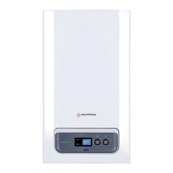
- Page 1 ENERWA 24 / 28 / 33 ENERWA PLUS 24 / 28 / 33 / 42 / 45 ENERWA PLUS SYSTEM 24 / 28 / 33 CONDENSING COMBI & SYSTEM BOILERS INSTALLATION & USER MANUAL...
-
Page 2: Table Of Contents
Others ......................20 5.2. PARTS COMPRISING THE COMBI PART .......... 42 2.6. REMOTE CONTROL AND CONTROL ACCESSORIES 5.2.1. Comprising The Heat Only Boiler ............43 (OPTIONAL) ..................21 2.6.1. Remote control with room thermostats ..........21 5.3. BOILER FIRST START-UP CONTROL LIST ........44 warmhaus.com... -
Page 3: Dear Customer
1015 spare part payments. WARMHAUS A.Ş. reserves the right to make all kinds of technical and commercial amendments without giving information and rejects all responsibilities depending on misspelling. ENERWA & PLUS COMBI & SYSTEM BOILERS INSTALLATION & USER MANUAL CODE-ENG... -
Page 4: Boiler Gas Categories & Destinations
Gas categories for Warmhaus boilers applied on CE certification on SZU Test / BRNO are given bellow; - the appliance category(ies) in relation to the direct countries of destination has been spesified EN 15502-1; GAR Certificate E-30-00300-18 product ID Nr. CE-1015CT0615 - the country(-ies) of destination, in accordance with EN ISO 3166-1;... -
Page 5: Gas Leakages
2. INSTALLATION PERSONNEL SECTION 2.1. CONTENTS OF PACKING BOX Warmhaus is sold as two boxes with combi and flue set. Combi box contains below listed materials and small box contains exhaust gas flue pipes. 150.11.606.000028 Figure 2 User's Guide Figure 3 Connection accessories I. -
Page 6: Combi Installation Rules
85 °C in the rated heat capacity of the appliance is not exceeded. according to the technique to full or semi-full brick wall according to installation scheme and with connection screws and not to be used for MODE RESET Figure 6 Boiler Services & Clearances warmhaus.com... -
Page 7: Dimensions And Connections
2.2.4. Dimensions and Connections ENERWA PLUS SYSTEM 24 ENERWA PLUS SYSTEM 28 ENERWA PLUS SYSTEM 33 10 10 Key for figures: CH Flow (5) CH Flow (5) CH Return (6) CH Return (6) 1) 230 V AC Main Power Supply 2) Manometer 3) Safety Valve Drainage Line 4) Gas Inlet Line... -
Page 8: Natural Gas Connection (Appliance Category I2H)
ENERWA PLUS 24 ENERWA PLUS 28 ENERWA PLUS 33 ENERWA 24 ENERWA PLUS 42 ENERWA 28 ENERWA PLUS 45 ENERWA 33 WARMHAUS LAWA CENTRAL HEATING FLO DOMESTIC HOT WATE GAS INLET DOMESTIC HOT WATE CENTRAL HEATING RE FILLING VALVE MANOMETER... -
Page 9: Installation At Partially Protected Exteriors
Mount ng plate connect on n pple 20 mm (3/4") Mount ng plate connect on n pple 20 mm (3/4”) Mount ng plate Spher cal natural gas valve w th yellow handle 20 mm (3/4”) Spher cal natural gas valve 20 mm (3/4") N pple 20 mm (3/4”) N pple 20 mm (3/4") P gta l 20 mm (3/4") -
Page 10: Filling/Emptying Radiator Installation
Figure 13 Pump Flow Rate / Pressure graphic have a pump with Automatic Air Figure 14 Pump Flow Rate / Pressure graphic of Enerwa of Enerwa 24 and Enerwa Plus 24 Vent Valve and modulation. 28, Enerwa 33 and Enerwa Plus 28, Enerwa Plus 33... -
Page 11: Enerwa Plus System 24 / Enerwa Plus System 28 / Enerwa Plus System 33 Circulation Pump
2.3.4. Enerwa Plus System 24 / Enerwa Plus System 28 / Enerwa Plus System 33 Circulation Pump GRUNDFOS UPM3 15-70 CAOD AA CE MARK COMFORMITY WITH FOLLOWING EMC Directive (2004/108/EC), RELEVANT EC DIRECTIVES Low voltage Directive (2006/125/EC) Ecodesign Directive (2009/125/EC) Power Grundfos UPM3 15-70 CAOD AA Energy Efficiency lndex (EEI) (EN16297/3) -
Page 12: Installation Diagram
Figure 20 Scheme of use of the boiler in a double pipe heating installation system. Figure 21 Scheme of use of the boiler in a mobile tubular distributed heating installation system. Figure 22 Scheme of use of the boiler in a mobile tubular distributed underfloor heating installation system. warmhaus.com... -
Page 13: Filling The Siphon For Condensation Line
Water / Air proof 2.3.7. Filling the siphon for Condensation Line 1. Ensure the discharge of condensate complies with any national or local Outdoor flusher insulation regulations in force. After the wall hanging operation of condensing boiler electrical connections, radiator lines, hot tap water connections and condensation water drainage line 2. -
Page 14: Combi Flue Connections
• 2 impermeability bolts within the hermetic flue set (2) are placed into Boiler should only be installed with original Warmhaus air suction and internal pipe slots at both ends of the 90° Bend. exhaust gas discharge device made of plastic material. Plastic channels •... - Page 15 (Ø 60/100 мм) L =10 м) (Ø 60/100 мм) L =10 м) мax мax 1.5°-3° 1.5°-3° 1.5°-3° : Total equivalent length ≤ 10 m . : a (90° elbow) + b + c ≤ 10 m 1. 90° bend 8. Interior flue pipe 2.
-
Page 16: Installation With Vertical Flue Sets (Ø 60/100 Mm)
Ø 80 intake and exhaust pipes is 30 metres, regardless from whether they are used for intake or exhaust. TOTAL VERTICAL LENGTH: A+B =32 m Figure 42 Vertical Air and Horizontal Flue Lengths warmhaus.com... -
Page 17: Concentric Flue Kits For Condensing Boilers (Ø60/100 Mm)
2.4.5. Concentric Flue Kits For Condensing Boilers (Ø60/100 mm) Product Name Product Code (Ø60/100) Condensing Concentric Horizontal Flue Set 15311014000002 (White) Horizontal From the center of the elbow Terminal = 115 + 790 = 905 mm Total (Ø60-100) Condensing Vertical Flue Set with Adapter L= [L =1000+500+145] = 1645 mm Term... -
Page 18: Twin Flue Kits For Condensing Boilers (Ø80/Ø80 Mm)
0121_00.D190515 Ø80 Exterior Wall Rosette Ø80 x 145 mm 15311660600098 0120_00.D190515 Ø80 Flue Vertical Outlet Ø80 mm; L = 145 mm 15311660600100 Adapter with Condensate Trap 0122_00.D190515 Ø80 Vertical Flue Kit Ø80 mm; L = 861 mm 15311660600097 0123_00.D190515 warmhaus.com... -
Page 19: Peripheral Distances Of Flue Output Connections
2.4.7. Peripheral Distances of Flue Output Connections In order to position the flue set output pipe Terminal Position with Minimum Distance (mm) A Below an opening 300 B Above an opening 300 C Horizontally to an opening 300 Flue outlets must not be subject to any blockage and Below gutters, soil pipes or drainpipes ... -
Page 20: Distance Of Flue Gas Installation From Combustible Building Materials
• Passages and corridors, the boiler is given with "X" type socketless special power source cables. "Warmhaus boiler has an IPX5D protection level. Power supply cable should be • Narrow eaves gaps, connected by relying on earth connection and L-N poles in a 230 V +%10; -%15 •... -
Page 21: Remote Control And Control Accessories (Optional)
2.6. REMOTE CONTROL AND CONTROL ACCESSORIES (OPTIONAL) 2.6.1. Remote control with room thermostats Product Name Explanation Product View With minimal dimensions and decreased 4 button keypad Remote control which is connected to boiler with cable can work in modulation, run weekly programs, Clewa adjust hot usage water and show boiler fault code in the screen and reset it. -
Page 22: Position Of Thermostat
Wi-Fi Smart Room Thermostat Set 2.6.2. Position of thermostat Instruction for Installation: Installation of the appliance shall be carried out only by Warmhaus Authorized Service. The dual cable required for installation shall be provided by the dealer/customer. Room thermostat shall... -
Page 23: Typical Installation Diagram
2.7. TYPICAL INSTALLATION DIAGRAM 2.7.1. Connection diagrams to the electronic board of electronic auxiliary equipment of boilers and cascade control Enerwa Plus System 24 / Enerwa Plus System 28 / Enerwa Plus System 33 CP09 °C MASTER MLC27 COM2 COM1 COM1 FREE CONTACT... -
Page 24: Scheme With One Boiler: 1 Radiator Circuit Enerwa Plus System 24 / Enerwa Plus System 28 / Enerwa Plus System 33
Hot Water Storage Sens or 2 x 1.0 mm CONDENSATION WATER DRAINAGE LINE NG GAS LİNE COLD WATER COLD WATER FOR FILLING FOR FILLING Figure 53 Enerwa System Single Boiler System Diagram (1 HT + Hot Water Storage Tank) warmhaus.com... -
Page 25: Typical Installation Scheme Cascade System With Enerwa Boilers Plus System 24 / Enerwa Plus System 28 / Enerwa Plus System 33
2.7.4. Typical Installation Scheme Cascade System with Enerwa Boilers Plus System 24 / Enerwa Plus System 28 / Enerwa Plus System 33 Figure 54 Cascade System with Enerwa System and 1 Radiator (High Temperature) Circuit + Floor Heating (Low Temperature) Circuit and Hot Water Storage Tank Scheme Example ENERWA &... -
Page 26: User's Section
Call the gas company or Authorized Service. (See 1.3 GAS LEAKAGES) First start should be performed by the Warmhaus Authorized Service for your safety and preventing void warranty scope. Our Authorized Service will give you required information about use of boiler after performing initial controls of your boiler and starting for the first time. -
Page 27: Control Panel Of Enerwa Model Combi & System Boiler Devices
3.2. CONTROL PANEL OF ENERWA MODEL COMBI & SYSTEM BOILER DEVICES Figure 55 Control panel of Enerwa boiler Figure 56 Enerwa boiler control panel screen BUTTONS and PUSHBUTTONS RESET: It is used for re-starting the combi boiler and eliminating the failure in case of combi boiler failure. -
Page 28: Selection Of On/Off/Standby And Summer/Winter Modes
°C symbol flashes temperature with temperature adjustment besides the DHW temperature value. Screen buttons (see.Figure 48) between 25 – 80 light turns off after adjustment. °C, screen lights when buttons are pressed and °C symbol flashes besides the radiator temperature value. warmhaus.com... -
Page 29: Resetting The Combi (Re-Starting)
3.3. CONTROL PANEL OF ENERWA PLUS COMBI 3.2.5. Resetting the Combi (Re-Starting) In cases that device gives failure/locking errors hold RESET button for 3-4 seconds, and release after completing the cycle on the screen. You can reset the device and have it repeated re-start operations A sample utilisation error;... -
Page 30: Selection Of On/Off/Standby And Summer/Winter Modes
Now, combi boiler is temperature adjustment button (3) (e.g. maximum 50 °C)}. at STANDBY position. The temperature value when electricity is supplied to the device is the temperature value of water in the heating circuit. warmhaus.com... -
Page 31: Operation In Summer Mode
3.3.6. Use with Room Thermostat (Optional) Combi Boiler has initial preparation for remote control connection via environment thermostats being sold as optional sets. All Warmhaus 3.3.4. Operation in Summer Mode thermostats can be connected with dual-wired cables. Carefully read user's Combi Boiler only operates for heating the domestic hot water in this mode.. -
Page 32: Use Of Outside Temperature Sensor (Optional)
Maintenance and Service Life: Warmhaus room thermostat should not come (P07) Controlled Power Increase Period. into contact with water or excessive humidity. Unless an external damage When boiler starts, it uses a controlled period defined for reaching the occurs, the room thermostat does not require any maintenance. -
Page 33: Troubleshooting
3.4. TROUBLESHOOTING 3.4.1. Failure Codes Table Error Description of the Error Malfunction Probable Cause Solution(s) Code E 01 Intervention of exhaust Boiler does not work, > Flue Sensor faulty 1-) Reset & Restart boiler Thermostat (Open E01 error code flashing 2-) Call for authorised service Combustion Chamber boiler ) - Page 34 Boiler does not work, > Calibration not done 1-) Call For service E62 error code > Replacing board but not flashing on service the screen key from the board dismantled > Service key damaged or disconnected > Updating Software (probable) warmhaus.com...
- Page 35 Error Description of the Error Malfunction Probable Cause Solution(s) Code E 71 Condensate Line / Boiler does not work, > Blockage in the Condensate 1-) Check syphone against water blokage. Siphon Clogging E71 error code flashing Siphon or pipe 2-) If fault still persists call for authorised service. on the screen >...
- Page 36 2-) Call for authorised service at first flashing on the screen (1) Call the Authorized Service if failure continues. (2) 81 numbered failure corresponds any blocking in the exhaust gas pipe. In such case, you should consult the authorized service technician before re-starting the combi. warmhaus.com...
-
Page 37: Recommendations For Economical Use Of Combi
CONSIDERATION FOR WARRANTY CONDITIONS Your boiler is adjusted at ECO mode for economic use, we recommend not This warranty given by Warmhaus does not cover elimination of failures to change. arising from abnormal use of the product and also out of the warranty scope... -
Page 38: Technical Datas
4. TECHNICAL DATAS Enerwa 24 & Enerwa Plus 24 & Enerwa 28 & Enerwa Plus 28 & TECHNICAL DATA UNIT Enerwa Plus System 24 Enerwa Plus System 28 Gas Circuit METHANE METHANE BUTAN PROPANE METHANE METHANE BUTAN PROPANE Gas Type... - Page 39 Enerwa 33 & Enerwa Plus 33 & Enerwa Plus System 33 Enerwa Plus 42 Enerwa Plus 45 METHANE METHANE BUTAN PROPANE METHANE METHANE BUTAN PROPANE METHANE METHANE BUTAN PROPANE 3,402 4,127 0,992 1,302 1,61 4,19 1,66 0,434 0,524 0,133 0,168 0,70 0,72 0,28...
-
Page 40: Product Fiche & Erp Data
Auxiliary boiler Brand Name WARMHAUS Warmhaus ısıtma ve Sogutma Sistemleri San. Tic. A.Ş. Manufacturer adress Taşpınar Mahallesi, TEKNOSAB 1. Cadde No: 12, 16700, Karacabey / Bursa / Türkiye All spesific precautions for assembly, installation and maintanance are described in the operating and installation manual. Read and follow the operating and installation manual. -
Page 41: Energy Label
4.2. ENERGY LABEL Enerwa Plus 24 Enerwa 24 Enerwa 28 Enerwa 33 2019 2019 2019 2019 Enerwa Plus 33 Enerwa Plus 42 Enerwa Plus 45 Enerwa Plus 28 2019 2019 2019 2019 ENERWA & PLUS COMBI & SYSTEM BOILERS INSTALLATION & USER MANUAL CODE-ENG... -
Page 42: First Starting Of Boiler
In order to keep the boiler within scope of warranty; first start must be - Boiler electricity connection should be made via 2 or 3 Amps fuse. performed by Warmhaus Authorized Service. Below given initial preparations - Ensure that no electricity interruption is available at your home. -
Page 43: Comprising The Heat Only Boiler
5.2.1. Comprising The Heat Only Boiler ENERWA PLUS SYSTEM 24 / ENERWA PLUS SYSTEM 28 / ENERWA PLUS SYSTEM 33 1. Flue Outlet 11. Condensation water Discharge Hose 21. 3 Bar safety Valve 2. Flue Condensation Pan 12. Flow Manifold 22. -
Page 44: Boiler First Start-Up Control List
5.3. BOILER FIRST START-UP CONTROL LIST The following form will be filled in by the Warmhaus Authorised Service during the first start-up of the appliance and, if deemed appropriate, it will be operated within the warranty. BOILER Form NO: SSH-FR 00 -000-01 R.T:13.04.2021 Date: ..... - Page 45 There is an earthed socket at a maximum distance of 50 cm from the device or a 2-4 Amp (N or W) automaton mounted on the electrical phase connection must be connected. If there is no earthed socket, a 3x1.5 TTR cable must be drawn from the nearest junction box and a grounded socket must be installed or a (N or W) automaton mounted on the electrical phase connection must be installed (The device must not be activated with a mobile extension cable) "Is the grounding of the device made in accordance with the standards? In places where there is no earthing, zeroing will not be made from...
- Page 46 warmhaus.com...
- Page 47 All descriptions and illustrations provided in this document have been carefully prepared but we reserve the right to make changes and improvements in our products which may affect the accuracy of the information contained in this leaflet. All goods are sold subject to our standard Conditions of Sale which are available on request.
- Page 48 ENERWA 24 / 28 / 33 ENERWA PLUS 24 / 28 / 33 / 42 / 45 ENERWA PLUS SYSTEM 24 / 28 / 33...
Need help?
Do you have a question about the ENERWA PLUS 42 and is the answer not in the manual?
Questions and answers